

Sensors and Methods for Mobile Robot Positioning
Sensors and Methods for Mobile Robot Positioning
Sensors and Methods for Mobile Robot Positioning

You also want an ePaper? Increase the reach of your titles
YUMPU automatically turns print PDFs into web optimized ePapers that Google loves.
14 Part I <strong>Sensors</strong> <strong>for</strong> <strong>Mobile</strong> <strong>Robot</strong> <strong>Positioning</strong><br />
There are two basic types of optical encoders: incremental <strong>and</strong> absolute. The incremental version<br />
measures rotational velocity <strong>and</strong> can infer relative position, while absolute models directly measure<br />
angular position <strong>and</strong> infer velocity. If non volatile position in<strong>for</strong>mation is not a consideration,<br />
incremental encoders generally are easier to interface <strong>and</strong> provide equivalent resolution at a much<br />
lower cost than absolute optical encoders.<br />
1.1.1 Incremental Optical Encoders<br />
The simplest type of incremental encoder is a single-channel tachometer encoder, basically an<br />
instrumented mechanical light chopper that produces a certain number of sine- or square-wave<br />
pulses <strong>for</strong> each shaft revolution. Adding pulses increases the resolution (<strong>and</strong> subsequently the cost)<br />
of the unit. These relatively inexpensive devices are well suited as velocity feedback sensors in<br />
medium- to high-speed control systems, but run into noise <strong>and</strong> stability problems at extremely slow<br />
velocities due to quantization errors [Nickson, 1985]. The tradeoff here is resolution versus update<br />
rate: improved transient response requires a faster update rate, which <strong>for</strong> a given line count reduces<br />
the number of possible encoder pulses per sampling interval. A very simple, do-it-yourself encoder<br />
is described in [Jones <strong>and</strong> Flynn, 1993]. More sophisticated single-channel encoders are typically<br />
limited to 2540 lines <strong>for</strong> a 5-centimeter (2 in) diameter incremental encoder disk [Henkel, 1987].<br />
In addition to low-speed instabilities, single-channel tachometer encoders are also incapable of<br />
detecting the direction of rotation <strong>and</strong> thus cannot be used as position sensors. Phase-quadrature<br />
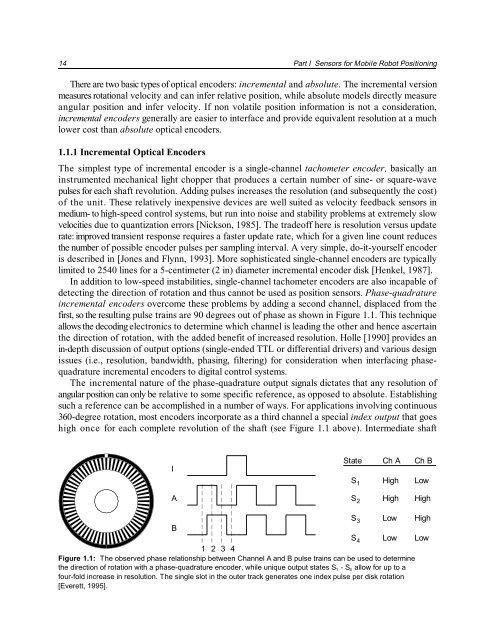
incremental encoders overcome these problems by adding a second channel, displaced from the<br />
first, so the resulting pulse trains are 90 degrees out of phase as shown in Figure 1.1. This technique<br />
allows the decoding electronics to determine which channel is leading the other <strong>and</strong> hence ascertain<br />
the direction of rotation, with the added benefit of increased resolution. Holle [1990] provides an<br />
in-depth discussion of output options (single-ended TTL or differential drivers) <strong>and</strong> various design<br />
issues (i.e., resolution, b<strong>and</strong>width, phasing, filtering) <strong>for</strong> consideration when interfacing phasequadrature<br />
incremental encoders to digital control systems.<br />
The incremental nature of the phase-quadrature output signals dictates that any resolution of<br />
angular position can only be relative to some specific reference, as opposed to absolute. Establishing<br />
such a reference can be accomplished in a number of ways. For applications involving continuous<br />
360-degree rotation, most encoders incorporate as a third channel a special index output that goes<br />
high once <strong>for</strong> each complete revolution of the shaft (see Figure 1.1 above). Intermediate shaft<br />
I<br />
State<br />
S<br />
1<br />
Ch A<br />
High<br />
Ch B<br />
Low<br />
A<br />
S2 High High<br />
S3 Low High<br />
B<br />
S4 Low Low<br />
1 2 3 4<br />
Figure 1.1: The observed phase relationship between Channel A <strong>and</strong> B pulse trains can be used to determine<br />
the direction of rotation with a phase-quadrature encoder, while unique output states S 1 - S 4 allow <strong>for</strong> up to a<br />
four-fold increase in resolution. The single slot in the outer track generates one index pulse per disk rotation<br />
[Everett, 1995].


