

Sensors and Methods for Mobile Robot Positioning
Sensors and Methods for Mobile Robot Positioning
Sensors and Methods for Mobile Robot Positioning

You also want an ePaper? Increase the reach of your titles
YUMPU automatically turns print PDFs into web optimized ePapers that Google loves.
50 Part I <strong>Sensors</strong> <strong>for</strong> <strong>Mobile</strong> <strong>Robot</strong> <strong>Positioning</strong><br />
Figure 2.16: a. Ideal B-H curve.<br />
b. Some minor hysteresis in the actual curve results in a residual non-zero<br />
value of B when H is reduced to zero, known as the retentivity. (Adapted from<br />
Halliday <strong>and</strong> Resnick, 1974; Carlson <strong>and</strong> Gisser, 1981).<br />
capability of the core is substantially reduced.<br />
Consider again the cylindrical rod sensor presented in Figure 2.17, now in the absence of any<br />
external magnetic field B . When the drive coil is energized, there will be a strong coupling between<br />
e<br />
the drive coil <strong>and</strong> the sense coil. Obviously, this will be an undesirable situation since the output signal<br />
is supposed to be related to the strength of the external field only.<br />
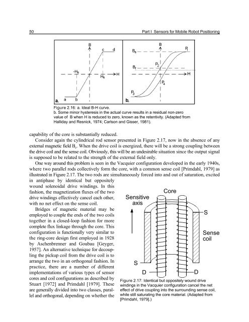
One way around this problem is seen in the Vacquier configuration developed in the early 1940s,<br />
where two parallel rods collectively <strong>for</strong>m the core, with a common sense coil [Primdahl, 1979] as<br />
illustrated in Figure 2.17. The two rods are simultaneously <strong>for</strong>ced into <strong>and</strong> out of saturation, excited<br />
in antiphase by identical but oppositely<br />
wound solenoidal drive windings. In this<br />
fashion, the magnetization fluxes of the two<br />
drive windings effectively cancel each other,<br />
with no net effect on the sense coil.<br />
Bridges of magnetic material may be<br />
employed to couple the ends of the two coils<br />
together in a closed-loop fashion <strong>for</strong> more<br />
complete flux linkage through the core. This<br />
configuration is functionally very similar to<br />
the ring-core design first employed in 1928<br />
by Aschenbrenner <strong>and</strong> Goubau [Geyger,<br />
1957]. An alternative technique <strong>for</strong> decoupling<br />
the pickup coil from the drive coil is to<br />
arrange the two in an orthogonal fashion. In<br />
practice, there are a number of different<br />
implementations of various types of sensor<br />
cores <strong>and</strong> coil configurations as described by<br />
Stuart [1972] <strong>and</strong> Primdahl [1979]. These<br />
are generally divided into two classes, parallel<br />
<strong>and</strong> orthogonal, depending on whether the<br />
Sensitive<br />
axis<br />
S<br />
D<br />
Core<br />
D<br />
S<br />
Sense<br />
coil<br />
Figure 2.17: Identical but oppositely wound drive<br />
windings in the Vacquier configuration cancel the net<br />
effect of drive coupling into the surrounding sense coil,<br />
while still saturating the core material. (Adapted from<br />
[Primdahl, 1979].)


