SurePOS 500/600 Series Installation and Operation Guide
SurePOS 500/600 Series Installation and Operation Guide
SurePOS 500/600 Series Installation and Operation Guide

Create successful ePaper yourself
Turn your PDF publications into a flip-book with our unique Google optimized e-Paper software.
|<br />
|<br />
|<br />
|<br />
|<br />
|<br />
|<br />
|<br />
|<br />
|<br />
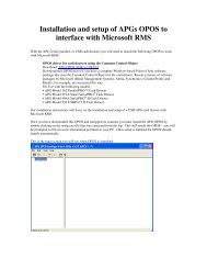
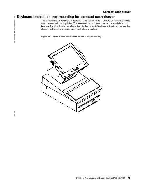
Keyboard integration tray mounting for compact cash drawer<br />
The compact-size keyboard integration tray can only be mounted on a compact-size<br />
cash drawer without a printer. The compact cash drawer can accommodate a<br />
keyboard <strong>and</strong> a distributed character display or an APA display. A printer can not be<br />
placed on the compact-size keyboard integration tray.<br />
Figure 56. Compact cash drawer with keyboard integration tray<br />
Compact cash drawer<br />
|<br />
|<br />
Chapter 5. Mounting <strong>and</strong> setting up the <strong>SurePOS</strong> <strong>500</strong>/<strong>600</strong> 75
Compact cash drawer<br />
|<br />
|<br />
|<br />
|<br />
|<br />
|<br />
|<br />
|<br />
|<br />
Start here:<br />
1. Remove the rear cover on the cash drawer. While pressing in on the two<br />
buttons located on the sides of the cash drawer, pull back on the rear cover<br />
back to remove it. Discard this rear cover. A new rear cover is used for the<br />
keyboard-integration kit installation.<br />
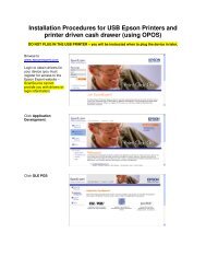
2. Place the integration tray ▌A▐ on the cash drawer <strong>and</strong> secure it to the cash<br />
drawer with four screws ▌B▐ as shown in Figure 57.<br />
F<br />
E<br />
D<br />
C<br />
B<br />
|<br />
|<br />
|<br />
|<br />
|<br />
|<br />
|<br />
|<br />
|<br />
A<br />
Figure 57. Installing the keyboard integration tray on a cash drawer<br />
3. Place the plastic insulator plate ▌C▐ on the integration tray while aligning the<br />
four screw holes on the insulator plate with the four screw holes on the<br />
keyboard integration tray.<br />
4. Attach mounting plate ▌D▐ to the keyboard integration tray with four plastic<br />
washers <strong>and</strong> screws.<br />
5. Attach fence ▌E▐ to the integration tray with six screws.<br />
76 <strong>SurePOS</strong> <strong>500</strong>/<strong>600</strong> <strong>Series</strong> <strong>Installation</strong> <strong>and</strong> <strong>Operation</strong> <strong>Guide</strong>
Compact cash drawer<br />
|<br />
|<br />
|<br />
|<br />
|<br />
|<br />
|<br />
|<br />
|<br />
|<br />
6. Prepare the <strong>SurePOS</strong> <strong>500</strong>/<strong>600</strong> to mount to the keyboard integration tray,<br />
perform the following steps:<br />
a. Remove the <strong>SurePOS</strong> <strong>500</strong>/<strong>600</strong> base cover by lifting up at the arrow<br />
located at rear of the cover. While rotating the rear of the cover upward,<br />
slide the cover toward the rear until it is free, as shown in Figure 11 on<br />
page 20.<br />
Attention: The <strong>SurePOS</strong> <strong>500</strong>/<strong>600</strong> is top-heavy <strong>and</strong> may fall forward if it<br />
is not attached to a base foot, countertop, or integration tray. To prevent<br />
this, tilt the operator display to its rearmost position.<br />
|<br />
|<br />
|<br />
|<br />
|<br />
|<br />
|<br />
|<br />
|<br />
|<br />
|<br />
b. Remove the power supply (see “Power supply removal” on page 37).<br />
Notes:<br />
1) If you are routing cables underneath the counter, route them through<br />
the cable access hole in the counter.<br />
2) If you are routing cables on top of the counter, route them out the back<br />
of the system under the power supply bracket. Lay them flat along the<br />
countertop.<br />
c. Remove the base foot from the base mount by removing screws ▌A▐ <strong>and</strong><br />
▌B▐.<br />
Chapter 5. Mounting <strong>and</strong> setting up the <strong>SurePOS</strong> <strong>500</strong>/<strong>600</strong> 77
Compact cash drawer<br />
|<br />
A<br />
B<br />
|<br />
|<br />
|<br />
Figure 58. Removing the base foot from the <strong>SurePOS</strong> <strong>500</strong>/<strong>600</strong><br />
78 <strong>SurePOS</strong> <strong>500</strong>/<strong>600</strong> <strong>Series</strong> <strong>Installation</strong> <strong>and</strong> <strong>Operation</strong> <strong>Guide</strong>
Compact cash drawer<br />
|<br />
|<br />
|<br />
|<br />
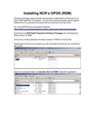
7. To attach the <strong>SurePOS</strong> <strong>500</strong>/<strong>600</strong> to the mounting plate on the compact cash<br />
drawer, perform the following steps:<br />
B<br />
C<br />
A<br />
|<br />
|<br />
|<br />
|<br />
|<br />
|<br />
|<br />
|<br />
|<br />
|<br />
|<br />
|<br />
Figure 59. Installing the <strong>SurePOS</strong> <strong>500</strong>/<strong>600</strong> on the compact cash drawer<br />
a. Loosely attach two base bracket screws ▌A▐ on the mounting plate. These<br />
screws are used to support the <strong>SurePOS</strong> <strong>500</strong>/<strong>600</strong> while securing it to the<br />
mounting plate as show in Figure 59.<br />
b. Position the two base bracket interlocking keyholes ▌B▐ over the two base<br />
bracket screws ▌A▐. Set the <strong>SurePOS</strong> <strong>500</strong>/<strong>600</strong> on two base bracket screws<br />
<strong>and</strong> slide back until they are locked into the keyholes. Tighten the two base<br />
bracket screws.<br />
c. Attach <strong>and</strong> tighten the other two base bracket screws ▌C▐ as show in<br />
Figure 59.<br />
Chapter 5. Mounting <strong>and</strong> setting up the <strong>SurePOS</strong> <strong>500</strong>/<strong>600</strong> 79
Compact cash drawer<br />
|<br />
|<br />
|<br />
8. Install the keyboard Y-cable. See Figure 60 for callout locations:<br />
A<br />
B<br />
D<br />
C<br />
|<br />
|<br />
|<br />
|<br />
|<br />
|<br />
|<br />
|<br />
|<br />
|<br />
Figure 60. Installing the keyboard Y-cable<br />
a. Route the Y-cable ▌A▐ <strong>and</strong> connect to the <strong>SurePOS</strong> <strong>500</strong>/<strong>600</strong> front<br />
connector panel keyboard/mouse connector. See “Connecting cables to the<br />
front panel” on page 85 for location.<br />
b. Attach the self-adhesive cable clamp ▌B▐ at the location shown in<br />
Figure 60. Insert Y-cable into cable clamp <strong>and</strong> route the Y-cable toward the<br />
front-left of the display.<br />
9. Install filler panel ▌C▐ into slot ▌D▐ as shown in the exploded view in Figure 60.<br />
Make sure that the Y-cable is routed to the left of the filler panel post.<br />
80 <strong>SurePOS</strong> <strong>500</strong>/<strong>600</strong> <strong>Series</strong> <strong>Installation</strong> <strong>and</strong> <strong>Operation</strong> <strong>Guide</strong>
Compact cash drawer<br />
|<br />
|<br />
|<br />
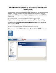
10. Install the keyboard. See Figure 61 for callout locations.<br />
D<br />
E<br />
B<br />
A<br />
|<br />
|<br />
|<br />
|<br />
|<br />
|<br />
|<br />
|<br />
|<br />
C<br />
Figure 61. Installing the keyboard onto the integration tray<br />
a. Attach keyboard cable ▌B▐ to Y-cable ▌C▐.<br />
b. Install keyboard filler panel ▌A▐ onto the integration tray while making sure<br />
that the keyboard filler panel post is inserted into the slot on the integration<br />
tray.<br />
c. Place keyboard ▌D▐ onto integration tray while pushing the excess<br />
keyboard cable back under the filler panel ▌A▐.<br />
Chapter 5. Mounting <strong>and</strong> setting up the <strong>SurePOS</strong> <strong>500</strong>/<strong>600</strong> 81
Compact cash drawer<br />
|<br />
|<br />
|<br />
|<br />
|<br />
|<br />
11. Prepare the distributed character display to be installed on an integration tray.<br />
a. Route the distributed character display cable through the mounting post<br />
(<strong>and</strong> post extension, if used) <strong>and</strong> plug the cable into the display, as shown<br />
in Figure 62.<br />
|<br />
|<br />
|<br />
|<br />
|<br />
Figure 62. Attaching the distributed character display cable<br />
b. Attach the character display top to its post by pressing the display down on<br />
the post until it snaps into place.<br />
82 <strong>SurePOS</strong> <strong>500</strong>/<strong>600</strong> <strong>Series</strong> <strong>Installation</strong> <strong>and</strong> <strong>Operation</strong> <strong>Guide</strong>
Compact cash drawer<br />
|<br />
|<br />
|<br />
|<br />
12. To install a distributed character display or an APA display, perform the<br />
following steps:<br />
A<br />
B<br />
F<br />
C<br />
D<br />
|<br />
|<br />
|<br />
|<br />
|<br />
|<br />
|<br />
|<br />
|<br />
|<br />
|<br />
|<br />
|<br />
|<br />
|<br />
|<br />
|<br />
|<br />
|<br />
|<br />
|<br />
|<br />
E<br />
Figure 63. Installing the distributed character display onto the compact keyboard integration<br />
tray<br />
a. Route the distributed character display cable ▌F▐ through the hole behind<br />
mounting post ▌C▐ as show in Figure 63. You may need to lay the display<br />
on its side to connect the display cable to the system unit rear connector<br />
panel.<br />
b. Route the distributed character display cable to the rear connector panel,<br />
passing it under the power supply bar on the base, <strong>and</strong> plug it into the<br />
15-pin serial connector, as shown in Figure 67 on page 86.<br />
c. Attach the distributed character display ▌A▐ to the cash drawer mounting<br />
post ▌C▐ with two thumbscrews ▌B▐ <strong>and</strong> snap the entire unit into place at<br />
the rear of the tray.<br />
13. If you are Installing a 4820 SurePoint Solution, goto“Installing IBM 4820<br />
SurePoint Solution <strong>and</strong> other external video displays” on page 93.<br />
14. If you are installing other peripheral devices, connect the peripheral cables to<br />
the appropriate ports on the <strong>SurePOS</strong> <strong>500</strong>/<strong>600</strong> rear connector panel. Make the<br />
connections on the bottom row of the panel first <strong>and</strong> work upward. See<br />
“Connecting cables to the rear connector panel tailgate” on page 86.<br />
Notes:<br />
a. If you are routing the cables under the counter, route all cables (including<br />
the ac power cord) through the cable access hole.<br />
Chapter 5. Mounting <strong>and</strong> setting up the <strong>SurePOS</strong> <strong>500</strong>/<strong>600</strong> 83
Compact cash drawer<br />
|<br />
|<br />
|<br />
|<br />
|<br />
|<br />
|<br />
|<br />
|<br />
|<br />
|<br />
|<br />
|<br />
|<br />
b. If you are routing the cables on top of the counter, route all cables out the<br />
rear of the system under the power supply support bar. Lay the cables flat<br />
along the countertop.<br />
15. Use tie-wraps to secure cables to the integration tray. See Figure 102 on<br />
page 130 for more information.<br />
16. Route the ac power cord under the power supply support bar.<br />
17. Reinstall the power supply.<br />
Note: When replacing the power supply, make sure that the U-shaped ends of<br />
the power supply bracket are on the metal bar ▌B▐ in Figure 25 on<br />
page 38. Tighten the two captive power supply thumb screws.<br />
18. Plug the ac power cord ▌A▐ to the power supply as shown in Figure 64.<br />
19. Connect the power connector cable ▌B▐ to the power supply.<br />
A<br />
B<br />
|<br />
|<br />
|<br />
|<br />
|<br />
|<br />
|<br />
|<br />
|<br />
|<br />
|<br />
|<br />
|<br />
|<br />
Figure 64. Location of power supply cords (top view of system)<br />
20. Replace the <strong>SurePOS</strong> <strong>500</strong>/<strong>600</strong> base cover.<br />
21. Install the new cash-drawer rear cover ▌D▐ onto the back of the cash drawer.<br />
Slide it over the two metal tabs ▌E▐ until it snaps into place. See Figure 63 on<br />
page 83 for locations.<br />
22. After your installation is complete, press the printer power switch under the<br />
printer cover to power on the printer.<br />
23. Switch ON the power to the <strong>SurePOS</strong> <strong>500</strong>/<strong>600</strong>. Verify that the system is<br />
operating correctly by checking the indicator lights (LEDs) on the front of the<br />
touch screen. See “Power On LED verification” on page 61.<br />
24. Install your software. See “Chapter 10. Installing software <strong>and</strong> support” on<br />
page 137 for more information.<br />
84 <strong>SurePOS</strong> <strong>500</strong>/<strong>600</strong> <strong>Series</strong> <strong>Installation</strong> <strong>and</strong> <strong>Operation</strong> <strong>Guide</strong>