IOM - Enviro-Tec
IOM - Enviro-Tec
IOM - Enviro-Tec

Create successful ePaper yourself
Turn your PDF publications into a flip-book with our unique Google optimized e-Paper software.
SERIES 700 ANALOG<br />
ELECTRONIC CONTROLS<br />
with ACT24 Actuator Supplement<br />
INSTALLATION &<br />
OPERATION MANUAL<br />
Stock ID: <strong>IOM</strong>-700<br />
October, 2000<br />
©2000 <strong>Enviro</strong>nmental <strong>Tec</strong>hnologies, Inc.<br />
Largo, FL
1.0 DEFINITIONS AND DESCRIPTIONS<br />
Series 700 <strong>IOM</strong> Table of Contents<br />
1.0 DEFINITIONS AND DESCRIPTIONS<br />
1.1 Thermostat (Figures 1a and 1b) .......................................................................................................... 3<br />
1.2 Controller (Figures 2a and 2b) ............................................................................................................ 5<br />
1.3 Actuators (Figures 3a, 3b and 4).......................................................................................................... 6<br />
2.0 INSTALLATION<br />
2.1 Inspection (Figure 5)........................................................................................................................... 7<br />
2.2 Coordination Of Trades ....................................................................................................................... 7<br />
2.3 Thermostat Mounting (Figures 6 through 10)...................................................................................... 7<br />
2.4 Wiring Installation ............................................................................................................................. 10<br />
2.5 Controller Wiring (Figure 11) ............................................................................................................ 10<br />
2.6 Thermostat Wiring............................................................................................................................. 11<br />
3.0 START-UP AND BALANCE PROCEDURE<br />
3.1 Initial Start-up Procedure - Test Clip (Figure 12)................................................................................ 12<br />
3.2 Initial Checks ..................................................................................................................................... 12<br />
3.3 Air Balancing Procedures ................................................................................................................... 13<br />
Table 3.1 – Control Sequence Charts ................................................................................................. 14<br />
4.0 TROUBLESHOOTING<br />
4.0 Quick Reference Table........................................................................................................................ 17<br />
4.1 Damper Motion ................................................................................................................................. 18<br />
4.2 Fan .................................................................................................................................................... 19<br />
4.3 Electric or Hot Water Heat ................................................................................................................. 20<br />
4.4 Night Setback .................................................................................................................................... 21<br />
4.5 Night Mode ....................................................................................................................................... 22<br />
4.6 Morning Warm-Up ............................................................................................................................ 23<br />
4.7 Auxiliary Minimum ............................................................................................................................ 23<br />
4.8 Changeover / Warm-Up ..................................................................................................................... 24<br />
4.9 Airflow Readings ............................................................................................................................... 25<br />
4.10 No Response to Thermostat............................................................................................................... 25<br />
4.11 Corrective Actions.............................................................................................................................. 26<br />
5.0 TEMPERATURE CALIBRATION, THERMOSTAT AND DUCT TEMPERATURE SENSOR<br />
5.1 Thermostat ........................................................................................................................................ 27<br />
5.2 Duct (Supply Air) Temperature Sensor ............................................................................................... 28<br />
6.0 SPARE PARTS LIST<br />
Actuator Replacement ............................................................................................................................... 29<br />
Thermostat ................................................................................................................................................ 29<br />
Controller .................................................................................................................................................. 29<br />
2.5" x 3.5" and 2" Thermostat Accessories.................................................................................................. 30<br />
7.0 AIRFLOW CALIBRATION CURVES<br />
SDR, VFR, CFR Volts vs. CFM (Figure 13) ................................................................................................... 31<br />
SDR, VFR, CFR ∆P (inches W.G.) (Figure 14) .............................................................................................. 32<br />
SSD, VVF, CVF Volts vs. CFM and ∆P (inches W.G.) (Figure 15) ............................................................... 32<br />
APPENDIX A, ACT24 <strong>IOM</strong>............................................................................................................................................33<br />
2<br />
Series 700 Installation & Operation Manual • October, 2000
1.0 DEFINITIONS AND DESCRIPTIONS<br />
Figure 1a, 2” Square Thermostat<br />
1.1 Thermostats (Figures 1a and 1b)<br />
Figure 1b, 2.5” x 3.5” Thermostat<br />
Two styles of thermostats have been produced. The previous thermostat (beige unit),<br />
approximately 2.5” x 3.5” on a 3.5” x 4.5” base, was standard through 1997. It is still supported,<br />
and is referred to as the 2.5” x 3.5” Thermostat throughout the remainder of this manual. The<br />
current thermostat (off-white 2” square, low profile unit) was introduced in 1998, and is referred<br />
to as the 2” Thermostat throughout the remainder of this manual. Items common to both are:<br />
a. Thermistor – Glass-encapsulated, hermetically sealed temperature sensing device mounted on front of<br />
the thermostat printed circuit board.<br />
b. Thermostat Packaging – Bubble pack design for protection during shipment. Terminal numbers,<br />
signal designations, serial number, inventory number and ETI job number are shown on outside of<br />
package, as well as Min., Max., and fan CFM on set CFM projects.<br />
1.1.1 2” Thermostat (Figure 1a)<br />
a. Setpoint Control – Hidden version shown. Also available with exposed dial in Fahrenheit or Celsius<br />
scale (see Figure 6).<br />
b. Enclosure – Protects thermostat and provides stable temperature environment for sensing. To remove<br />
cover, push firmly on one side (not top or bottom) of cover, and pull other side away from base.<br />
c. Connectors – Protected terminal block on back of thermostat base. Terminal designations are<br />
engraved on back of base.<br />
d. Minimum Flow Adjustment – White potentiometer on printed circuit board (see Figure 1a). CW<br />
rotation increases minimum CFM.<br />
e. Maximum Flow Adjustment – White potentiometer on printed circuit board (see Figure 1a). CW<br />
rotation increases maximum CFM.<br />
f. Auxiliary (Heating) Minimum Adjustment – White potentiometer (see Figure 1a) allowing increased<br />
flow when heat is energized. CW rotation increases heating CFM. Should always be turned fully<br />
clockwise if heating minimum feature is not used.<br />
g. Temperature Calibration – Factory set. Adjustment rarely required.<br />
October, 2000 • Series 700 Installation & Operation Manual 3
1.0 DEFINITIONS AND DESCRIPTIONS<br />
1.1.2 2.5 x 3.5” Thermostat (Figure 1b)<br />
a. Setpoint Controls “A” and “B” – Green thumbwheel potentiometers mounted on front of the<br />
thermostat printed circuit board. “A” adjusts temperature setpoint for day or cooling operation. “B”<br />
adjusts temperature setpoint for night (setback) or heating (changeover) operation.<br />
b. Enclosure – Protects thermostat and provides stable temperature environment for sensing. Vertical fins<br />
on cover face must be on left hand side of enclosure directly over thermistor.<br />
c. Connectors – Captive screw type. Terminal designations are printed on solder side of printed circuit<br />
board.<br />
d. Minimum Flow Adjustment – Top blue potentiometer on back of printed circuit board (viewed from<br />
left side of stat). CW rotation increases minimum CFM.<br />
e. Maximum Flow Adjustment – Bottom blue potentiometer. CW rotation increases maximum CFM.<br />
f. Fan Start/Stop Adjustment (optional) – Middle blue potentiometer on variable volume fan sequences.<br />
CW rotation increases CFM at which fan will start (decreasing CFM) or stop (increasing CFM). Full CCW<br />
rotation causes fan to start/stop by temperature demand rather than CFM (1° below temperature<br />
setpoint).<br />
g. Auxiliary (Heating) Minimum Adjustment (optional) – Middle blue potentiometer allowing increased<br />
flow when heat is energized. CW rotation increases heating CFM.<br />
4<br />
Series 700 Installation & Operation Manual • October, 2000
Figure 2a<br />
Controller<br />
Figure 2b<br />
First Generation Controller<br />
(No Longer Available)<br />
1.2 Controller (Figures 2a and 2b)<br />
Three versions of controllers have been offered. The first generation (Figure 2b) was housed in a black<br />
plastic enclosure, used an AC actuator drive, and was standard from 1986 through most of 1990. The<br />
latest generation (Figure 2a) uses a blue circuit board, DC actuator drive, and was standard from 1990<br />
through mid-2000. An interim version was offered for around six months in 1990. It was similar in<br />
appearance to the latest generation, but used a green circuit board and AC actuator drive.<br />
a. Thermostat and Sensor Connectors – One-piece, captive screw terminal type for reliable connections.<br />
b. 24 VAC and Control Output Connectors – Male, ¼", quick connect type.<br />
c. Labels – Computer printed with serial number, inventory number and ETI job number.<br />
d. Flow Transducer – Device mounted on controller, which produces electronic signal proportional to flow.<br />
Tubing for the transducer is connected to the inlet of the VAV terminal at the factory.<br />
e. D.C. Actuator Drive – Incorporates reversing and current limit circuitry, which removes power from motor<br />
when a mechanical stop is met.<br />
October, 2000 • Series 700 Installation & Operation Manual 5
1.0 DEFINITIONS AND DESCRIPTIONS<br />
1.3 Actuators (Figures 3a, 3b and 4)<br />
Several versions of actuator have been offered. The first generation (Figure 3b) was initially offered with an<br />
AC motor through most of 1990. At the end of 1990, a DC motor was substituted for the AC motor. A<br />
version with a rectifier board was available for controls with AC drives. In 1992, a rotary actuator was<br />
released (Figure 3a). It was used through early 2000, when it was replaced with the ACT24 (Figure 4,<br />
Appendix A).<br />
a. Rotary – 90° rotation. Attaches to damper shaft with approximate 1/8” gap between bottom of<br />
actuator and bottom of control enclosure and use 2 set screws. Full open to close travel time is 2 to 3<br />
minutes.<br />
b. Rack & Pinion – Rack and pinion type with lubricated steel gear insert in rack for strength. Pin at end<br />
of rack attaches to damper shaft with bolt. Rack contains internal stops. Full travel time is<br />
approximately 70 seconds. Actuators using this drive train are no longer available. See Section 5 for<br />
current substitute.<br />
c. D.C. Motor – Reversible D.C. Motor. Output at pinion gear is approximately 2 RPM, depending on load.<br />
Connections are made using 3/16" quick connect receptacles.<br />
d. A.C. Motor – Hansen “Synchron” model is two motors stacked together, each with 24 VAC, 4 W<br />
winding. The output at pinion gear is 1 RPM. White wires are used for common, blue wire for CW<br />
motor and yellow for CCW rotation. A 13 ohm resistor is provided on the controller to prevent damage<br />
by high voltage. Actuators using this motor are no longer available. See Section 5 for current<br />
substitute.<br />
C<br />
Figure 3b, Rack & Pinion Actuator<br />
C or D<br />
Figure 3a, Rotary Actuator<br />
Figure 4, ACT24 Actuator<br />
(See Appendix A)<br />
6<br />
Series 700 Installation & Operation Manual • October, 2000
Figure 5, Typical Component Mounting<br />
On units with electric heat, high voltage components are located inside the electric heat cabinet.<br />
2.1 Inspection (Figure 5)<br />
2.0 INSTALLATION<br />
Upon receipt of VAV terminals, check controls for shipping damage such as loose or broken connectors, broken<br />
actuator or controller housing, loose or disconnected tubing and loose wiring. Also inspect both before and<br />
after installation for damage caused by abuse or mishandling. A diagram of a typical control component<br />
mounting configuration is provided above in Figure 5.<br />
2.2 Coordination of Trades<br />
Contractor should see that all trades involved with both the VAV terminals and the electronic controls (including<br />
thermostats) have a copy of the documentation and submitted control sequence data prior to installation.<br />
2.3 Thermostat Mounting<br />
Thermostats may be shipped separately from the terminal units, or located inside the control enclosure as per<br />
your local sales representative’s request. The thermostat may be mounted directly to drywall or optionally to a<br />
horizontally mounted, single gang junction box.<br />
2.3.1 Drywall Mounting 2.5” x 3.5” Thermostat (Figures 6 and 7)<br />
a. Drill holes in wall for cable from controller and two wall anchors. Insert wall anchors in wall.<br />
b. Run cable through L-shaped hole in thermostat base and fasten base to wall with screws provided as<br />
shown in sketch.<br />
c. Mount PC Board on base so setpoint dial is at bottom between board and base (exposed setpoint unit)<br />
or at top (standard unit). Use guide pins to align. Fasten PC board to base using plastic retaining pins<br />
provided.<br />
d. Snap cover onto base, making sure the vertical slots are on left side (<strong>Enviro</strong>-<strong>Tec</strong> ® is right side up).<br />
October, 2000 • Series 700 Installation & Operation Manual 7
2.0 INSTALLATION<br />
Drywall Mounting, 2.5” x 3.5”<br />
Standard Setpoint<br />
(Figure 6)<br />
Drywall Mounting, 2.5” x 3.5”<br />
Exposed Setpoint<br />
(Figure 7)<br />
Single Gang Junction Box<br />
Mounting, 2.5” x 3.5”<br />
(Figure 8)<br />
8<br />
Series 700 Installation & Operation Manual • October, 2000
2.3.2 Single Gang Junction Box Mounting 2.5 x 3.5” Thermostat (Figure 8)<br />
a. Install right-hand (self-threading) screw first, (left-hand for exposed setpoint thermostat) through bracket<br />
and fix bracket to junction box.<br />
b. Install left-hand, (self-threading) screw second (right-hand for exposed setpoint thermostat) through<br />
thermostat base plate and bracket into junction box. Do not tighten fully.<br />
c. Install center sheet metal screw through thermostat base plate and bracket.<br />
d. Tighten all three screws and mount circuit board on base per 2.31c.<br />
e. Snap cover onto base, making sure <strong>Enviro</strong>-<strong>Tec</strong> ® is right side up.<br />
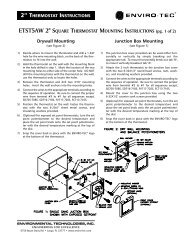
2.3.3 Drywall Mounting 2” Thermostat (Figure 9)<br />
a. Drill a 1 3/8” hole for the wire-mounting block on the back of the thermostat to fit into the wall.<br />
b. Hold the thermostat on the wall with the mounting block in the hole drilled, and mark the location of the<br />
two holes to either side of the center hole. CAUTION — DO NOT DRILL THE HOLES WITH THE STAT ON<br />
THE WALL!<br />
c. Remove the stat, drill two 3/16” holes, and insert the wall anchors.<br />
d. Connect the wires to the appropriate terminals according to the wiring diagram. Be sure to connect the<br />
jumper wire from terminal 3 to terminal 1, if required.<br />
e. Position the thermostat on the wall. Fasten the thermostat with the two 6-20x1” sheetmetal screws and<br />
insulated washers provided.<br />
f. For exposed setpoint (optional) stats, turn the setpoint potentiometer to the desired temperature and place<br />
the setpoint knob onto the setpoint potentiometer with the temperature marking at the top of the dial.<br />
g. Snap the cover back in place with the <strong>Enviro</strong>-<strong>Tec</strong> ® logo at the bottom of the stat.<br />
Drywall Mounting, 2” Thermostat<br />
(Figure 9)<br />
2.3.4 Single Gang Junction Box Mounting 2” Thermostat (Figure 10)<br />
a. To mount the junction box cover horizontally break out tab “B”, vertically break out tab “A”.<br />
b. Attach the 2” stat to the junction cover with the two 6-32x1/2” round head screws, nuts, washers and<br />
insulation washers provided.<br />
c. Connect the wires to the appropriate terminals according the wiring diagram. Be sure to connect the<br />
jumper wire from terminal 3 to terminal 1 as required.<br />
d. Mount the cover to the junction box using the two 6-32x1/2” counter sunk screws provided.<br />
e. For (optional) exposed setpoint stats, turn the setpoint potentiometer to the desired temperature and place<br />
the set point knob onto the setpoint potentiometer with the temperature marking at the top of the dial.<br />
f. Snap the cover back in place with the <strong>Enviro</strong>-<strong>Tec</strong> ® logo at the bottom of the thermostat.<br />
October, 2000 • Series 700 Installation & Operation Manual 9
2.0 INSTALLATION<br />
Single Gang Junction Box Mounting,<br />
2” Thermostat<br />
(Figure 10)<br />
2.4 Wiring Installation<br />
Warning – Disconnect all power supplies to the system before wiring to avoid damage to the equipment<br />
or possible electrical shock.<br />
a. Recommended wire type for external control connections is 18 to 20 AWG stranded copper.<br />
b. Wiring Diagrams – Refer to <strong>Enviro</strong>-<strong>Tec</strong> ® Submittal Data (installed in the control enclosure cover on later<br />
models) to determine correct terminals for wiring. Prior to wiring, ensure that the submittal sequence<br />
matches the control model number. (Refer to Parts List in Section 6). Obtain submittal data (control<br />
sequence wiring diagram) from sales representative.<br />
c. Control wiring to thermostat and optional remote contact closures should not be routed close to AC<br />
power (line voltage) wiring, electrical machinery, or lighting to reduce the possibility of electrical<br />
interference.<br />
2.5 Controller Wiring<br />
a. Thermostat and Control Input Connections:<br />
1. Using a small screwdriver, turn screw fully CCW.<br />
2. Strip ¼” of insulation and insert into connector (Figure 11).<br />
3. Turn screw fully CW. Make sure connector clamps uninsulated<br />
portion of wire. Do not overtigthen.<br />
b. 24 VAC Input and Control Output Connections:<br />
1. Strip ½” of insulation from 18-20 AWG stranded copper wire.<br />
2. Attach a ¼” quick connect spade type receptacle to the<br />
uninsulated portion of the wire using a set of crimpers.<br />
Screw Terminal Connector<br />
(Figure 11)<br />
3. Push receptacle over spade and printed circuit board. Caution: Fit is tight. Wiggling or pulling off<br />
with pliers may damage board. If removal of a connector is required, pry off with screwdriver,<br />
supporting PC board with your fingers.<br />
10<br />
Series 700 Installation & Operation Manual • October, 2000
2.6 Thermostat Wiring<br />
2.6.1 2.5” x 3.5” Thermostat<br />
a. Remove cover from thermostat. If a locking cover has been provided, a 1/16” allen wrench will be required<br />
to remove the two allen screws which lock the cover in place.<br />
b. Remove printed circuit board from base. If plastic retaining pins are tight, pry up the pins with a small<br />
screwdriver. Caution: Take care not to damage components on printed circuit board when prying out<br />
plastic retaining pins.<br />
c. Strip ¼” of insulation from the wire.<br />
d. Insert wire in connector and tighten screw. Caution: Do not overtighten screws. Make sure connector<br />
clamps the uninsulated portion of wire.<br />
e. Repeat Steps C and D for all wire and terminals.<br />
f. Replace board on base using guide pins to align. Insert plastic retaining pins into large holes in printed<br />
circuit board and push through into base.<br />
g. Replace cover, making sure vertical openings on face are positioned on left side. If the cover is locking,<br />
reinsert allen screws removed in Step A so that cover cannot be removed.<br />
2.6.2 2” Thermostat<br />
a. If thermostat has already been mounted to wall, remove it. Terminal numbers are engraved on back of<br />
thermostat above and below two row, six position barrier terminal block.<br />
b. Strip 5/16” insulation from wire.<br />
c. Insert wire under terminal retainer. Make sure retainer clamps bare wire, not insulation.<br />
d. Repeat Steps B and C for all wires shown connected in application submittal data diagram. If diagram<br />
shows a wire from controller connected to Terminal 3, remove factory installed jumper wire. Otherwise,<br />
attach bare end of factory installed jumper to Terminal 1.<br />
CAUTION: ALWAYS VERIFY THAT WIRING IS CORRECT BEFORE APPLYING POWER.<br />
October, 2000 • Series 700 Installation & Operation Manual 11
3.0 START-UP AND BALANCE PROCEDURE<br />
3.0 START-UP AND BALANCE PROCEDURE<br />
3.0.1 Required Items<br />
a. 1/8" flat blade screwdriver<br />
b. Digital voltmeter capable of reading to the hundredths place and capable of reading 30 Volts AC/DC<br />
c. Airflow Calibration Curves (Figure 13 or 15, pages 30 & 31)<br />
3.0.2 Optional Items<br />
a. Test Clips for voltmeter (Figure 12)<br />
b. Magnehelic or manometer (optional) with a full scale reading of 0 “ – 2.0” W.G.<br />
Test Clip (Figure 12)<br />
3.1 Initial Start-up Procedure<br />
The following items must be checked before beginning the air balancing procedure.<br />
a. Verify 2.5 x 3.5” stat or 2 x 2” thermostat prior to balancing<br />
b. Inspect all electrical connections to ensure proper fit and location, in accordance with the wiring diagram.<br />
Transformer leads carry a high voltage on the primary windings and associated terminals. Lethal voltages<br />
may be present.<br />
c. Check primary voltage to the control transformer (if applicable). Check that the output voltage is between<br />
22 and 28 VAC. If outside these limits, remove power immediately and determine the cause of improper<br />
power. (See Troubleshooting – Section 4.0.)<br />
d. Check for primary airflow or static pressure if the damper is closed, in the inlet duct.<br />
e. The unit should be checked for proper sequence response before attempting to balance system.<br />
Refer to <strong>Enviro</strong>-<strong>Tec</strong> ® submittal data located in control enclosure cover in later models. Contact your<br />
<strong>Enviro</strong>-<strong>Tec</strong> ® sales representative if submittal data is not available.<br />
f. Room temperature must be between 65° and 85°F.<br />
g. For optimum control accuracy, a straight section of duct at least 1.5 duct diameters long and the same<br />
diameter as the inlet collar should be installed upstream of the terminal inlet.<br />
Minimum airflow must always be set first.<br />
3.2 Initial Checks<br />
a. 2.5 x 3.5” Thermostat - Most adjustments are made at the thermostat; however, some sequences of<br />
operation may require additional adjustments at the terminal unit. Remove the thermostat cover as<br />
previously described in Section 2.6.1. Flow adjustments (blue potentiometers) are located on the<br />
underside of the thermostat circuit board and to the left (Figure 1). Temperature adjustments are<br />
located on the front side (Figure 1). Test loops along the bottom side of the thermostat board (Figure 1)<br />
are used for measuring various voltages during the balancing procedure. Check Table 3.1 to determine<br />
which test loop to use. Always connect the black (common) clip lead to the wire marked TP1 located just<br />
below the connector labeled “2.”<br />
12<br />
Series 700 Installation & Operation Manual • October, 2000
. 2” Thermostat - Most adjustments are made at the thermostat; however, some sequences of operation may<br />
require additional adjustments at the terminal unit. Remove the thermostat cover by pushing firmly on one<br />
side (not top or bottom) of cover and pulling other side of cover away from base. Figure 1a shows location<br />
of flow and temperature setpoint adjustments. If applicable, make sure unit is in cooling and/or day mode.<br />
If this is not the case, the unit may be forced into cooling by removing the duct sensor wire attached to<br />
terminal 3 on the controller, and/or forced into day mode by removing the pressure switch wire from<br />
terminal 1 or terminal 4 (whichever is applicable). To read the calibration voltage (VSP), connect the red (+)<br />
lead of the voltmeter to the balance post under the temperature setpoint potentiometer, and the black (-)<br />
lead of the voltmeter to the wire loop (common) shown in Figure 1a.<br />
3.3 Air Balancing Procedures for 2.5 x 3.5” Stat (Sequences ending in “R” & “A) and<br />
2” Stat (Sequences ending in “S”)<br />
For model #’s SSD, CVF, VVF, SDD, use flow chart (Figure 15) for the linear probe.<br />
For model #’s SDR, CFR, VFR, DDR, use flow chart (Figure 13) for the FlowStar probe.<br />
The procedures described below use voltage-flow setpoints for setting airflow rates for each size unit. The curves<br />
provided in this manual (Figures 13, 14 and 15) allow setting of maximum and minimum volume to design air<br />
limits. The pressure signal from the inlet sensors can be used to verify flows and assist in the system balancing.<br />
Connect a magnehelic, inclined manometer or other differential pressure measuring device to the balancing taps<br />
provided (Figure 5). The pressure differential between high and low represents the sensed velocity pressure<br />
amplified in the inlet duct.<br />
3.3.1 Air Terminal Units<br />
a. Remove thermostat cover as previously described in Section 2.6.1.a (2.5” x 3.5” thermostat) or Section 3.2.b<br />
(2” thermostat).<br />
b. On 2.5” x 3.5” thermostat, refer to Table 3.1 and remove wire on terminal 3 as required. On the 2”<br />
thermostat, turn the potentiometer labeled “AUX” fully clockwise. Do not remove wire on terminal 3 of<br />
2” thermostat.<br />
c. Use the airflow calibration curves (Figures 13 and 15) to determine the balance (VSP) voltages required for<br />
the desired minimum and maximum airflow settings. For example, if a minimum CFM value of 200 is<br />
desired for a 6” SDR box, the corresponding voltage is 9.4 VDC.<br />
d. For control sequences SD713 through SD718 with “A” or “R” suffix (2.5” x 3.5” thermostat), go to Step I.<br />
Otherwise, continue to Step E.<br />
e. Turn the temperature setpoint to full heating. Adjust the potentiometer labeled “MIN” (2” thermostat) or<br />
the top blue potentiometer (2.5” x 3.5” thermostat), to the desired minimum airflow voltage.<br />
f. Turn the temperature setpoint to full cooling. Adjust the potentiometer labeled “MAX” (2” thermostat) or<br />
the bottom blue potentiometer (2.5” x 3.5” thermostat), to the desired maximum airflow voltage.<br />
g. For control sequences SD713 through SD718S (2” thermostat), turn temperature setpoint to full heating and<br />
adjust potentiometer labeled "AUX" to the desired heating minimum.<br />
h. Sequences SD701-704 (all suffixes), SD713-SD716 (all suffixes) and FV701-704S are now balanced. For all<br />
other control sequences go to Step K.<br />
i. Turn the temperature setpoint to full cooling. Adjust the top blue potentiometer to the desired minimum<br />
airflow voltage. Adjust the bottom blue potentiometer to the desired maximum airflow voltage.<br />
j. Turn the temperature setpoint to full heating. Adjust the middle blue potentiometer to the desired heating<br />
minimum airflow voltage. Go to Step H.<br />
k. Find the category below applying to the control sequence being balanced.<br />
October, 2000 • Series 700 Installation & Operation Manual 13
3.0 START-UP AND BALANCE PROCEDURE<br />
Table 3.1<br />
Control Sequence Charts<br />
SSD & SDR SINGLE DUCT TERMINALS<br />
Sequence Number Balance Morning Warm-up Remove Change Over Dual Min<br />
Test Loop<br />
Wire #3<br />
SD701R 3 No No No No<br />
SD702R-4R 5 No No No No<br />
SD705R 4 Yes Yes No No<br />
SD706R-8R 5 Yes Yes No No<br />
SD709R 4 No Yes Yes No<br />
SD710R-12R 5 No Yes Yes No<br />
SD713R-15R 5 No No No Yes<br />
SD716R-18R 5 Yes Yes No Yes<br />
CFR, CFRQ, CVF & CVFQ FAN TERMINALS<br />
Sequence Number Balance<br />
Test Loop<br />
Night Setback Remove<br />
Wire #3<br />
Night Mode Morning<br />
Warm-up<br />
FC701R-4R 5 No No Yes No<br />
FC705R-8R 5 Yes Yes No No<br />
FC709R 3 No No No No<br />
FC710R-12R 5 No No No No<br />
FC713R-16R 5 No Yes Yes Yes<br />
FC717R-20R 5 Yes Yes No Yes<br />
VFR & VVF FAN TERMINALS<br />
Sequence Number Balance Test Loop Morning<br />
Warm-up<br />
Cool Fan<br />
Remove<br />
Wire #3<br />
FV701R-4R 5 4 No No No<br />
FV705R-8R 5 4 No Yes Yes<br />
FV709R-12R 5 4 Yes No No<br />
FV713R-16R 5 4 Yes Yes Yes<br />
FV717R-20R 5 4 Yes Yes No<br />
FV721R-24R 5 4 Yes Yes Yes<br />
Night Setback<br />
NOTE: The above tables also apply to “A” sequence (SD701A) and older control sequences (SD701).<br />
14<br />
Series 700 Installation & Operation Manual • October, 2000
3.3.2 Model VVF-II/VFR Units with the 2.5 x 3.5” stat<br />
a. Move the (+) lead of your digital voltmeter to Balance Post number 4.<br />
b. Refer to the Airflow Calibration Curves to determine what voltage corresponds to the start/stop CFM desired<br />
(i.e., a fan start/stop CFM setpoint of 250 is desired for a box Size 6, the corresponding voltage is 8.1 VDC).<br />
c. With the information attained on Step b, adjust the middle potentiometer on the side of the stat until your<br />
digital voltmeter reads the desired fan start/stop CFM voltage.<br />
d. NOTE: Adjust the fan start/stop potentiometer fully CCW if you want the fan to start and stop based on<br />
temperature demand instead of CFM.<br />
e. Reconnect wire to terminal 3 of the thermostat.<br />
3.3.3 Sequences SD705R-SD712R, SD716R-SD718R, FC713R-FC720R, FV717R-FV724R<br />
a. If applicable, reconnect wire to terminal 3 of thermostat.<br />
b. Adjust the blue potentiometer on the controller labeled “Duct Sensor” to a temperature midway between<br />
the expected cold and warm air temperatures. Recommended minimum difference in cold and warm air<br />
temperature is 10°F.<br />
3.3.4 All Series Flow Fan Terminals (Models CFR, CFRQ, CVF, CVFQ)<br />
a. These terminals need the fan speed adjusted so that when drawing maximum primary airflow, no air is<br />
either entering or leaving the plenum air inlet. Turn temperature setpoint to full cooling, and wait for<br />
damper to move to maximum CFM setpoint.<br />
b. A three speed switch or a motor speed adjustment terminal strip is used in conjunction with an<br />
electronic fan speed controller to make this adjustment. Locate these components in the terminal’s<br />
control or electric heat enclosure. A hole in the front cover of the fan speed controller allows<br />
adjustment using a small screwdriver. Verify the adjustment is fully CW.<br />
CAUTION: LETHAL VOLTAGES ARE PRESENT!<br />
• If a motor speed adjustment terminal strip is provided instead of a three speed switch,<br />
disconnect all power before attempting to adjust or change motor speed terminals.<br />
• Do not adjust the fan speed controller using your hand.<br />
• Do not touch the back of the fan speed controller.<br />
• Do not adjust the second, factory set potentiometer, only accessible from the back, or<br />
warranty will be voided.<br />
c. If air is leaving the plenum air inlet, go to Step 3.3.4.d. Otherwise, go to Step 3.3.4.g.<br />
d. Adjust three speed switch to “Med” or remove power, then remove end of jumper connected to “Low<br />
Spd” terminal and reinstall on the “Med Spd” terminal.<br />
e. If removed, re-apply power. If air is leaving the plenum air inlet, go to Step 3.3.4.f. Otherwise, go to<br />
Step 3.3.4.g.<br />
f. Adjust three speed switch to “High”, or remove power, then remove end of jumper connected to “Med<br />
Spd” terminal and reinstall on the “High Spd” terminal. Re-apply power.<br />
g. Using the hole in the front cover of the fan speed controller and a small screwdriver, slowly adjust CCW<br />
so that no air is either entering or leaving the plenum air inlet.<br />
October, 2000 • Series 700 Installation & Operation Manual 15
3.0 START-UP AND BALANCE PROCEDURE<br />
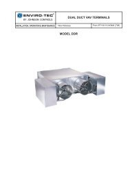
3.3.5 Dual Duct DD701R and DD701S<br />
a. Dual Duct sequences have the air flow adjustments on the controller board instead of the<br />
thermostat. Disregard all statements that refer to the airflow adjustments on the thermostat.<br />
The same flow curves are used to set CFM.<br />
b. Connect the red (+) lead from the DC voltmeter to the VSP test loop and the black (-) lead to the Com<br />
test loop on the cold deck controller (ETPD0U).<br />
c. Turn the temperature setpoint potentiometer on the thermostat to full heating and the R143<br />
potentiometer on the cold deck controller, fully clockwise. On the cold deck controller (ETPD0U), adjust<br />
R150 until the voltmeter reads 17 VDC. Move the test leads from the cold deck controller to the VSP<br />
loop and the Com loop on the hot deck controller (ETPD0HU). Adjust R143 on the hot deck for the<br />
desired maximum CFM voltage.<br />
d. Turn the temperature setpoint potentiometer on the thermostat to full cooling and the R143<br />
potentiometer on the hot deck controller fully clockwise. On the hot deck controller, adjust R150 until<br />
the meter reads 17 VDC. Move the test leads back to the VSP test loop and the Com test loop on the<br />
cold deck controller. Adjust R143 on the cold deck to the desired maximum CFM voltage.<br />
3.3.6 Dual Duct DD702R<br />
a. Connect the red (+) lead from a DC voltmeter to the VSP test loop and the black (-) lead to the Com<br />
test loop on the cold deck controller (ETPD0U).<br />
b. Turn the cooling setpoint potentiometer on the thermostat to full heating, and the R143 on the cold<br />
deck controller, fully clockwise. Adjust R150 on the cold deck until the voltmeter reads 17 VDC. Turn<br />
the temperature setpoint potentiometer on the thermostat to full cooling and adjust R150 on the cold<br />
deck controller until the meter reads the desired maximum CFM voltage.<br />
c. Move the test leads from the cold deck controller to the hot deck controller, the red (+) lead on the<br />
VSP test loop and the black (-) test lead on the Com test loop.<br />
d. Turn the heating setpoint potentiometer on the thermostat fully counter clockwise and R143 on the hot<br />
deck controller fully clockwise. Adjust R150 on the hot deck controller until the voltmeter reads 17<br />
VDC. Turn the heating setpoint potentiometer fully clockwise and adjust R143 on the hot deck<br />
controller to the desired maximum CFM voltage.<br />
16<br />
Series 700 Installation & Operation Manual • October, 2000
4.0 TROUBLESHOOTING<br />
WARNING: WITH ALL ELECTRICAL DEVICES THERE IS DANGER OF ELECTRICAL SHOCK. LETHAL VOLTAGES ARE<br />
PRESENT AT THE SUPPLY CONNECTIONS OF ALL POWER TRANSFORMERS. USE CAUTION WHEN MEASURING<br />
OPERATING VOLTAGES OF THESE UNITS.<br />
a. At the beginning of each section are “Common Problems.” To save time, check these items first.<br />
b. Many of the procedures refer to Normal and/or Option Mode. Normal Mode refers to daytime, cooling<br />
operation. A unit with options may be forced into Normal Mode by removing the duct sensor wire from<br />
terminal 3, and/or removing a wire from the pressure switch.<br />
c. Many of the procedures in this section require taking voltage readings. This may be done easily by using meter<br />
leads with spring-loaded clips instead of the usual probes. These leads free your hands for other work; they<br />
may be purchased at consumer electronics stores. For controller terminals not having test loops, voltages may<br />
be read by holding the meter lead directly on the screw terminal or tab connector (as applicable). Test points<br />
followed by a “(+)” are to be attached to the “+” jack of your meter, which is usually the red lead. Test<br />
points followed by a “(-)” are to be attached to the “-” jack of your meter, which is usually the black lead.<br />
d. Since most of the procedures are temperature related, you must ensure that the ambient temperature at the<br />
thermostat is 55-85°F. Also, the primary air supply must be 55-85°F, with 0.5-2.5" W.G. inlet static pressure.<br />
e. Some procedures require the balancing voltages to be changed for test purposes. It is a good idea to record<br />
these so they may be restored after troubleshooting is complete.<br />
f. The following table is a list of unit functions. Follow the table in the order presented to determine the<br />
specific problem(s). For instance, to diagnose a single duct, cooling only terminal which does not move its<br />
damper when the thermostat is turned from full heating to full cooling (or vice versa), first go through Section<br />
4.1 (Damper Motion), then 4.9 (No Response to Thermostat).<br />
Table 4.0 – Quick Reference<br />
Problem With<br />
Proceed to Section<br />
Damper Motion 4.1<br />
Fan 4.2<br />
Electric or Hot Water Heat 4.3<br />
Night Setback 4.4<br />
Night Mode 4.5<br />
Morning Warm-up 4.6<br />
Auxiliary Minimum 4.7<br />
Changeover 4.8<br />
Airflow Readings 4.9<br />
No Response to Thermostat 4.10<br />
Corrective Actions 4.11<br />
October, 2000 • Series 700 Installation & Operation Manual 17
4.0 TROUBLESHOOTING<br />
4.1 Damper Motion<br />
NOTE: The current 700 Series Controller drives a DC actuator motor or an ACT24 Actuator in conjunction with an<br />
ETAC DC to AC actuator drive interface. Since the output is time-proportioned, it may be necessary to observe the<br />
actuator for up to 30 seconds before proceeding with each step.<br />
COMMON PROBLEMS<br />
• Output wires backwards.<br />
• Option mode is enabled; verify the unit is in Normal Mode before continuing with this procedure.<br />
Table 4.1<br />
Step Action Result Proceed To<br />
4.1.1 Set the MIN (and AUX MIN, if equipped) airflow to 17 VDC per Section 3.0,<br />
“Balancing”<br />
Good<br />
Bad<br />
4.1.2 Set maximum airflow to 5.0 VDC Good<br />
Bad<br />
4.1.3 Connect DC voltmeter between Vsp (+) and Com (-) test loops on controller.<br />
Vary thermostat setpoint “A” and verify the voltage goes from 17 VDC to 5.0<br />
VDC.<br />
4.1.4 Disconnect both air hoses at the sheet metal enclosure entrance and verify<br />
voltage between Vf (+) and Com (-) test loops on controller is between 14.5 –<br />
17 VDC.<br />
4.1.5 Turn temperature setpoint (“A” if dual setpoints) to full cooling. Verify damper<br />
shaft rotates CCW (open).<br />
4.1.6 Turn temperature setpoint (“A” if dual setpoints) to full heating. Attach hose<br />
from “high” side of airflow probe to transducer port on controller labeled<br />
high. Verify voltage between VF (+) and Com (-) test loops on controller<br />
measures between 0-8 VDC.<br />
4.1.7 Turn temperature setpoint (“A” if dual setpoints) to full heating. Verify<br />
damper shaft rotates CW (closed)<br />
4.1.8 Damper actuator controls are working correctly. If you have other problems,<br />
refer to Table 4.0<br />
4.1.9 If damper actuator is an ACT24, determine if it is functional according to the<br />
Checkout Instructions of attached ACT24 <strong>IOM</strong>. Otherwise, go to Step 4.1.10<br />
4.1.10 Measure voltage between actuator terminals with the red (+) lead on terminal<br />
with red dot. If voltage is less than +/- 1 VDC, go to Step 4.1.11. If voltage is<br />
between +1 and +3 VDC, go to Step 4.1.12. If voltage is between -1 and -3<br />
VDC, go to Step 4.1.13.<br />
4.1.11 Disconnect actuator wires and check for +/- 10 to 16 VDC between terminals<br />
13 and 14 of controller.<br />
4.1.12 Controller is driving actuator open, but actuator is stalled. If actuator is<br />
against either the damper’s mechanical stop or its own mechanical stop, go to<br />
Step 4.1.14. Otherwise, replace actuator.<br />
4.1.13 Controller is driving actuator closed, but actuator is stalled. If actuator is<br />
against either the damper’s mechanical or its own mechanical stop, go to Step<br />
4.1.14. Otherwise, replace actuator.<br />
4.1.14 Reverse the actuator wires to move the actuator off the stop. Place the wires<br />
back in the original position and verify the actuator moves back against the<br />
stop.<br />
Good<br />
Bad<br />
Good<br />
Bad<br />
Good<br />
Bad<br />
Good<br />
Bad<br />
Good<br />
Bad<br />
Good<br />
Bad<br />
Good<br />
Bad<br />
Good<br />
Bad<br />
4.1.2<br />
4.10<br />
4.1.3<br />
4.10<br />
4.1.4<br />
4.11.1<br />
4.1.5<br />
4.9<br />
4.1.6<br />
4.1.9<br />
4.1.7<br />
4.9<br />
4.1.8<br />
4.1.9<br />
4.11.3<br />
4.11.13<br />
4.11.13<br />
4.11.3<br />
4.11.3<br />
4.11.13<br />
18<br />
Series 700 Installation & Operation Manual • October, 2000
4.2 Fan<br />
NOTE: On VVF-II/VFR terminals, the fan relay is controlled by the electronic controller in Normal (day) Mode. It is<br />
engaged according to either primary airflow or ambient temperature, depending on the control sequence and<br />
balance settings.<br />
On CVF/II/CFR terminals, the fan relay is kept on in Normal Mode. In the Option Mode, the fan is cycled to either<br />
maintain temperature or off, depending on your sequence.<br />
COMMON PROBLEMS<br />
• Blown fan motor fuse.<br />
• Option Mode is enabled, verify unit is in Normal Mode.<br />
• Fan start/stop potentiometer (VVF-II/VFR models) misadjusted.<br />
• Blue and yellow wires swapped between transformer and controller.<br />
Table 4.2<br />
Step Action Result Proceed To<br />
4.2.1 If the unit in question is VVF-II/VFR<br />
If the unit in question is CVF-II/CFR<br />
4.2.2<br />
4.2.9<br />
4.2.2 Turn the fan start/stop (middle blue) potentiometer on the<br />
thermostat fully CCW.<br />
4.2.3 Connect DC voltmeter between Test Point 6 (+) and TP1 (-) on<br />
thermostat. Vary thermostat setpoint “A” and verify voltage<br />
goes from approximately 1VDC (CCW) to 17 VDC (CW).<br />
4.2.4 Connect DC voltmeter between terminal 5 (+) and Com (-) on<br />
controller. Vary thermostat setpoint “A” and verify voltage goes<br />
from approximately 1VDC (CCW) to 17 VDC (CW).<br />
4.2.5 Locate the fan relay/contactor. It is installed in either the<br />
control or heater enclosure.<br />
4.2.6 Turn thermostat setpoint (“A” if dual setpoints) to full cooling,<br />
then slowly turn it to full heating, verify the fan relay/contactor<br />
engages at 1 to 2° above ambient temperature.<br />
Good<br />
Bad<br />
Good<br />
Bad<br />
Good<br />
Bad<br />
4.2.4<br />
4.10<br />
4.2.5<br />
4.11.1<br />
4.2.10<br />
4.2.7<br />
4.2.7 Carefully check wiring to the fan relay/contactor per the<br />
sequence.<br />
4.2.8 Remove the wire from controller terminal 9 and touch it briefly<br />
to terminal 15. Verify the fan relay/contactor engages.<br />
4.2.9 Locate the fan relay/contactor installed in enclosure. Verify the<br />
relay is engaged.<br />
4.2.10 Fan controls are operating correctly in normal mode. To test the<br />
fan in an option mode or you have other problems, refer to<br />
Table 4.0.<br />
Good<br />
Bad<br />
Good<br />
Bad<br />
Good<br />
Bad<br />
4.2.8<br />
4.11.1<br />
4.11.3<br />
4.11.4<br />
4.2.8<br />
4.2.7<br />
October, 2000 • Series 700 Installation & Operation Manual 19
4.0 TROUBLESHOOTING<br />
4.3 Electric or Hot Water Heat<br />
COMMON PROBLEMS<br />
• Blown fan motor fuse.<br />
• Option mode is enabled; verify the unit is in Normal mode.<br />
• Blue and yellow wires swapped from transformer to controller.<br />
Table 4.3<br />
Step Action Result Proceed To<br />
4.3.1 Connect DC voltmeter between test point 6 (+) and TP1 (-) on<br />
thermostat. Vary thermostat setpoint “A” and verify voltage goes<br />
from approximately 1 VDC (CCW) to 17 VDC (CW).<br />
4.3.2 Connect DC voltmeter between controller terminal 5 (+) and Com (-).<br />
Slowly turn thermostat setpoint (“A” if dual setpoints) from heating<br />
to cooling and verify voltage goes from approximately 1 VDC (CCW)<br />
to 17 VDC (CW).<br />
4.3.3 Locate the heat relay(s) or contactors<br />
4.3.4 Turn thermostat setpoint (“A” if dual setpoints) to full cooling, slowly<br />
turn to heating. Verify the heat 1 relay/contactor engages at 2-3°<br />
above ambient temperature.<br />
4.3.5 If you have only one stage of electric heat, go to 4.3.6. Continue<br />
slowly turning (“A” if dual setpoints) to heating and verify heat 2 and<br />
3 engage in 1° increments.<br />
4.3.6 Check wiring to the heat relays/contactors per the wiring diagram. If<br />
correct, remove the wire from terminal output (10 through 12), and<br />
briefly touch it to terminal 15. Verify the heat relay/contactor<br />
engages.<br />
4.3.7 Heat controls are operating correctly in Normal Mode. To test the heat<br />
in an option mode or you have other problems, refer to Table 4.0.<br />
Good<br />
Bad<br />
Good<br />
Bad<br />
Good<br />
Bad<br />
Good<br />
Bad<br />
Good<br />
Bad<br />
4.3.2<br />
4.10<br />
4.3.3<br />
4.11.1<br />
4.3.5<br />
4.3.6<br />
4.3.7<br />
4.3.6<br />
4.11.3<br />
4.11.5<br />
20<br />
Series 700 Installation & Operation Manual • October, 2000
4.4 Night Setback<br />
COMMON PROBLEMS<br />
• Air hose on pressure switch connected to the low fitting instead of high.<br />
• Wires on pressure switch not connected to NC and COM.<br />
• Insufficient static pressure to keep pressure switch open.<br />
Table 4.4<br />
Step Action Result Proceed To<br />
4.4.1 Connect a DC voltmeter between controller terminals 1 (+) and Com (-).<br />
Verify voltage is 14-18 VDC.<br />
Good<br />
Bad<br />
4.4.6<br />
4.4.2<br />
4.4.2 Verify the wiring is correct. Remove the wire from controller terminal 1 and<br />
verify voltage from terminal 1 (+) to Com (-) is 14-18 VDC.<br />
Good<br />
Bad<br />
4.4.3<br />
4.11.3<br />
4.4.3 Disconnect the air hose to the pressure switch, reconnect the wire to<br />
terminal 1 and verify the voltage from controller terminal 1 (+) to Com (-)<br />
Good<br />
Bad<br />
4.4.4<br />
4.11.6<br />
is 0-1 VDC.<br />
4.4.4 Blow in the hose and verify the voltage from controller terminal 1 (+) to<br />
Com (-) jumps up to 14-18 VDC.<br />
Good<br />
Bad<br />
4.4.5<br />
4.11.6<br />
4.4.5 Verify primary static pressure is above 0.3” W.G. Good<br />
Bad<br />
4.11.6<br />
4.11.7<br />
4.4.6 Disconnect the air hose to the pressure switch. Verify voltage is 0-1 VDC. Good<br />
Bad<br />
4.4.7<br />
4.4.2<br />
4.4.7 Connect voltmeter from controller terminal 2 (+) to Com (-) and verify 0-1<br />
VDC.<br />
Good<br />
Bad<br />
4.4.8<br />
4.11.3<br />
4.4.8 Reconnect air hose to pressure switch. Verify voltage is 14-18 VDC. Good<br />
Bad<br />
4.4.9<br />
4.11.3<br />
4.4.9 Connect voltmeter between thermostat terminal 3 (+) and TP1 (-). Verify<br />
voltage is 14-18 VDC.<br />
Good<br />
Bad<br />
4.4.10<br />
4.11.1<br />
4.4.10 Disconnect air hose from pressure switch. Verify voltage is 0-1 VDC. Good<br />
Bad<br />
4.4.11<br />
4.11.1<br />
4.4.11 If the sequence uses a 2.5” x 3.5” stat, vary temperature setpoint “B” and<br />
verify it turns the fan on/off. If the sequence uses a 2” stat, turn the<br />
temperature setpoint 5°F above room temperature and vary the offset<br />
potentiometer (R107 on the controller) and verify it turns the fan on/off.<br />
4.4.12 Reconnect air hose and vary temperature setpoint (“A” if dual setpoints),<br />
verify it controls the damper.<br />
4.4.13 Night Setback is operating correctly. To test controls in an option mode or<br />
if you have other problems, refer to Table 4.0.<br />
Good<br />
Bad<br />
Good<br />
Bad<br />
4.4.12<br />
4.11.8<br />
4.4.13<br />
4.11.8<br />
October, 2000 • Series 700 Installation & Operation Manual 21
4.0 TROUBLESHOOTING<br />
4.5 Night Mode<br />
COMMON PROBLEMS<br />
• Air hose on pressure switch connected to LOW fitting instead of HIGH.<br />
• Wires on pressure switch not connected to NC and COM.<br />
• Insufficient static pressure to keep pressure switch open.<br />
Table 4.5<br />
Step Action Result Proceed To<br />
4.5.1a<br />
4.5.1a<br />
If the unit in question is FC701A-FC704R<br />
If the unit in question is FC713A-FC716R<br />
4.5.2<br />
4.5.10<br />
4.5.2 Verify voltage between controller terminals 4 (+) and Com (-)<br />
is 14-18 VDC.<br />
Good<br />
Bad<br />
4.5.7<br />
4.5.3<br />
4.5.3 Verify air pressure switch and controller wiring is correct.<br />
Remove the wire from controller terminal 4 and verify voltage<br />
from terminal 4 (+) to Com (-) is 14-18 VDC.<br />
Good<br />
Bad<br />
4.5.4<br />
4.11.3<br />
4.5.4 Temporarily disconnect the hose going to the pressure switch.<br />
Reconnect the wire to terminal 4, and verify voltage from<br />
controller terminal 4 (+) to Com (-) is 0-1 VDC.<br />
4.5.5 Blow in the hose going to airflow switch and verify voltage<br />
increases to 14-18 VDC.<br />
Good<br />
Bad<br />
Good<br />
Bad<br />
4.5.6 Verify primary static pressure above 0.3” W.G. Good<br />
Bad<br />
4.5.7 Remove air hose from pressure switch, verify voltage is 0-1 Good<br />
VDC.<br />
Bad<br />
4.5.8 Turn thermostat setpoint (“A” if dual setpoints) to full heating. Good<br />
Verify fan (and heat, if applicable) are off.<br />
Bad<br />
4.5.9 Reconnect air hose. Verify fan (and heat, if applicable) are on. Good<br />
Bad<br />
4.5.10 Turn duct sensor potentiometer on controller fully CW. Good<br />
Connect a DC voltmeter between controller terminals 1 (+) Bad<br />
and com (-). Verify voltage is 14-18 VDC<br />
4.5.11 Verify the air pressure switch and controller wiring are all<br />
correct. Remove the wire from controller terminal 1 and verify<br />
voltage from terminal 1 (+) to Com (-) is 14-18 VDC.<br />
4.5.12 Temporarily disconnect the hose going to the pressure switch.<br />
Reconnect the wire to terminal 1 and verify the voltage from<br />
controller terminal 1 (+) to Com (-) is 0-1 VDC.<br />
4.5.13 Night Mode is operating correctly. If you wish to test the<br />
controls in an option mode or you have other problems, refer<br />
to Table 4.0.<br />
Good<br />
Bad<br />
Good<br />
Bad<br />
4.5.5<br />
4.11.6<br />
4.5.6<br />
4.11.6<br />
4.11.6<br />
4.11.7<br />
4.5.8<br />
4.5.3<br />
4.5.9<br />
4.11.3<br />
4.5.13<br />
4.11.3<br />
4.5.7<br />
4.5.11<br />
4.5.12<br />
4.11.3<br />
4.5.5<br />
4.11.6<br />
22<br />
Series 700 Installation & Operation Manual • October, 2000
4.6 Morning Warm-Up (Control Sequences FV721 – 724A, R or S and FC717 – 720 A, R or S ONLY)<br />
If sequence uses changeover version of morning warm-up, go to 4.8.<br />
COMMON PROBLEM<br />
• Duct Sensor Setpoint out of adjustment: this should be set midway between expected cold supply and hot<br />
supply air temperatures. In lieu of this, set it to 70°F.<br />
Table 4.6<br />
Step Action Result Proceed To<br />
4.6.1 Disconnect both duct sensor wires from controller and verify duct sensor<br />
resistance is between 11 Kohms and 27 Kohms (temperature dependent:<br />
high value cool, low value warm).<br />
Good<br />
Bad<br />
4.6.2<br />
4.11.9<br />
4.6.2 Turn temperature setpoint (“A” if dual setpoints) to full heating. Force unit<br />
to day mode by removing pressure switch wire from terminal 1 or 4. Turn<br />
duct sensor potentiometer on controller fully CCW. Verify 15-18 VDC from<br />
terminal 5 to COM test loop on controller.<br />
4.6.3 Turn duct sensor potentiometer on controller fully CW. Verify 0-1 VDC from<br />
terminal 5 to COM test loop on controller.<br />
4.6.4 Morning Warmup is operating correctly. To test controls in another option<br />
mode or if you have other problems, refer to Table 4.0<br />
4.6.5 Duct sensor may be out of calibration. Attempt to calibrate using the<br />
procedure in Section 5.2.<br />
Good<br />
Bad<br />
Good<br />
Bad<br />
Good<br />
Bad<br />
4.6.3<br />
4.6.5<br />
4.6.4<br />
4.6.5<br />
4.6.4<br />
4.11.3<br />
4.7 Auxiliary Minimum<br />
COMMON PROBLEMS<br />
• Improper wiring.<br />
• Improper balancing: read Section 3.0 carefully to properly balance a unit having Aux Min (also known as a<br />
Dual Minimum or Heating Minimum).<br />
• Operator error: read the control sequence carefully to fully understand how Aux Min operates.<br />
• On units having Morning Warm-up, verify warm-up is not enabled before starting this procedure.<br />
Table 4.7 Auxiliary Minimum<br />
Step Action Result Proceed To<br />
4.7.1 Turn MIN and AUX MIN potentiometers fully CCW. Turn MAX potentiometers<br />
fully CW. Turn thermostat setpoint (“A” if dual setpoints) to full cooling. Verify<br />
damper is opening.<br />
Good<br />
Bad<br />
4.7.2 Verify voltage between thermostat terminals 4 (+) and TP1 (-) is 0-1 VDC. Good<br />
Bad<br />
4.7.3 Carefully check wiring per control sequence. Good<br />
Bad<br />
4.7.4 Replace thermostat and set potentiometers as in Step 4.7.1. Verify voltage Good<br />
between terminals 4 (+) and TP1 (-) is 0-1 VDC.<br />
Bad<br />
4.7.5 Turn thermostat setpoint (“A” if dual setpoints) fully CW. Verify voltage Good<br />
between thermostat terminals 4 (+) and TP1 (-) is 14-18 VDC.<br />
Bad<br />
4.7.6 Carefully check wiring per control sequence. Good<br />
Bad<br />
4.7.7 Replace thermostat. Verify voltage between terminals 4 (+) and TP1 (-) is 14-18 Good<br />
VDC. Set potentiometers as in Step 4.7.1 and turn temperature setpoint to full Bad<br />
heating.<br />
4.7.8 Verify voltage between controller test point VSP and Com (-) is 14-18 VDC. Good<br />
Bad<br />
4.7.9 Slowly turn the AUX MIN potentiometer on the thermostat CW and verify the<br />
voltage drops.<br />
Good<br />
Bad<br />
4.7.2<br />
4.10<br />
4.7.5<br />
4.7.3<br />
4.7.4<br />
4.11.1<br />
4.11.8<br />
4.11.3<br />
4.7.8<br />
4.7.6<br />
4.7.7<br />
4.11.1<br />
4.11.8<br />
4.11.3<br />
4.7.9<br />
4.10<br />
4.7.11<br />
4.7.10<br />
October, 2000 • Series 700 Installation & Operation Manual 23
4.0 TROUBLESHOOTING<br />
Table 4.7 Auxiliary Minimum (continued)<br />
4.7.10 Carefully check wiring per control sequence. Good<br />
Bad<br />
4.7.11 Check to ensure that the heat relay(s) are all ON. Good<br />
Bad<br />
4.7.12 Slowly turn Thermostat Setpoint (“A” if dual setpoints) CCW until heat 1 relay turns Good<br />
off. Verify voltage between controller test point VSP & COM (-) is 14-18 VDC. Bad<br />
4.7.13 Slowly turn the MIN potentiometer on the thermostat CW and verify the voltage Good<br />
drops.<br />
Bad<br />
4.7.14 Adjust the MIN potentiometer to 17 VDC. Turn the thermostat setpoint (“A” if dual Good<br />
setpoints) to full heating and adjust the AUX MIN potentiometer to 13.0 VDC. Turn Bad<br />
the thermostat setpoint (“A” if dual setpoints) to full cooling and adjust the MAX<br />
potentiometer to 5.0 VDC.<br />
4.7.15 Verify the damper opens, then modulates at its MAX position (which was set in the Good<br />
above step).<br />
Bad<br />
4.7.16 Turn the thermostat setpoint “A” fully CW and verify the damper goes to its AUX Good<br />
MIN position (which was set in 4.7.14).<br />
Bad<br />
4.7.17 Slowly turn thermostat setpoint “A” fully CCW until the Heat 1 relay turns off. Verify Good<br />
the damper goes almost closed; this will be the MIN position as set in 4.7.14. Bad<br />
4.7.18 Auxiliary Minimum is operating correctly. To test the controls in an option mode or<br />
if you have other problems, refer to Table 4.0.<br />
4.8 Changeover/Warm-Up (All Morning Warm-Up Sequences EXCEPT FV721 - 724 A, R or S,<br />
and FC717 – 720 A, R or S)<br />
COMMON PROBLEM<br />
• Duct Sensor Setpoint out of adjustment: this should be set midway between expected cold supply and hot<br />
supply air temperatures, in lieu of this set it to 70°F.<br />
Table 4.8 Changeover<br />
24<br />
Series 700 Installation & Operation Manual • October, 2000<br />
4.11.8<br />
4.11.1<br />
4.7.12<br />
4.3<br />
4.7.13<br />
4.10<br />
4.7.14<br />
4.10<br />
4.7.15<br />
4.7.10<br />
4.7.16<br />
4.1<br />
4.7.17<br />
4.10<br />
4.7.18<br />
4.10<br />
Step Action Result Proceed To<br />
4.8.1 Turn duct sensor potentiometer on controller fully CW. Connect DC voltmeter<br />
between terminals 2 (+) and 7 (-). Verify voltage is 14-18 VDC.<br />
4.8.2 Verify all wiring correct between thermostat and controller, per control<br />
sequence. If correct, disconnect both duct sensor wires from controller and<br />
verify duct sensor resistance is between 11 Kohms and 27 Kohms (temperature<br />
dependent: high value cool, low value warm).<br />
4.8.3 Reconnect duct sensor and remove wire from terminal 2. Turn duct sensor<br />
potentiometer on controller fully CW. Connect DC voltmeter between<br />
controller terminals 2 (+) and 7 (-). Verify voltage is 14-18 VDC.<br />
4.8.4 Turn duct sensor potentiometer on controller full CCW. Connect DC voltmeter<br />
between terminals 2 (+) and 7 (-). Verify voltage is 0-1 VDC.<br />
4.8.5 Turn temperature setpoint ("B" if dual setpoints) to full heating. Verify damper<br />
is opening.<br />
4.8.6 Turn temperature setpoint ("B" if dual setpoints) to full cooling. Verify damper<br />
is closing.<br />
4.8.7 Turn duct sensor potentiometer on controller fully CW. Turn temperature<br />
setpoint ("A" if dual setpoints) to full cooling. Verify damper is opening.<br />
4.8.8 Turn temperature setpoint ("A" if dual setpoints) to full heating. Verify damper<br />
is closing.<br />
4.8.9 Changeover is operating correctly. To test the controls in an option mode or if<br />
you have other problems, refer to Table 4.0.<br />
4.8.10 Duct sensor may be out of calibration. Attempt to calibrate using the<br />
procedure in Section 5.2.<br />
Good<br />
Bad<br />
Good<br />
Bad<br />
Good<br />
Bad<br />
Good<br />
Bad<br />
Good<br />
Bad<br />
Good<br />
Bad<br />
Good<br />
Bad<br />
Good<br />
Bad<br />
Good<br />
Bad<br />
4.8.4<br />
4.8.2<br />
4.8.3<br />
4.11.9<br />
4.11.8<br />
4.8.10<br />
4.8.5<br />
4.8.2<br />
4.8.6<br />
4.10<br />
4.8.7<br />
4.10<br />
4.8.8<br />
4.10<br />
4.8.9<br />
4.10<br />
4.8.9<br />
4.11.3
4.9 Airflow Readings<br />
COMMON PROBLEMS<br />
• Loose tubing at velocity probe in VAV terminal inlet.<br />
• Loose tubing at coupling (transition from black to clear tubing).<br />
• Loose tubing at controller.<br />
• Flex duct on inlet is bent too tightly. There should be a minimum of 1 ½ diameter of straight duct at the inlet<br />
(i.e., an 8” box would need 12” of straight duct).<br />
• HIGH and LOW tubing connections reversed at controller.<br />
Table 4.9<br />
Step Action Result Proceed To<br />
4.9.1 Disconnect both airflow hoses at the duct inlet. Connect voltmeter to “Vf”<br />
(+) and Com (-). Verify 14.5-18 VDC.<br />
Good<br />
Bad<br />
4.9.2<br />
4.11.3<br />
4.9.2 Blow gently through the airflow hose connected to HIGH on the controller.<br />
Verify voltage drops to 0-3 VDC.<br />
Good<br />
Bad<br />
4.9.3<br />
4.11.3<br />
4.9.3 The flow circuit seems to be operating correctly. Carefully check the items<br />
under “Common Problems” above.<br />
Good<br />
Bad<br />
4.11.10<br />
4.9.4<br />
4.9.4 Fix tubing and/or flex duct, and go to Step 4.9.1.<br />
4.10 No Response to Thermostat<br />
COMMON PROBLEMS<br />
• Incorrect wiring; check control sequence carefully.<br />
• Insufficient static air pressure.<br />
• Option mode is enabled; verify that the unit is in Normal Mode before continuing with this procedure.<br />
Table 4.10 No Response to Thermostat<br />
Step Action Result Proceed To<br />
4.10.1 Measure AC voltage between terminals 15 and 16 at the controller. Verify<br />
22.0-27.6 VAC.<br />
Good<br />
Bad<br />
4.10.2<br />
4.11.11<br />
4.10.2 Turn power off to the controller, remove the fuse and verify that fuse<br />
resistance is 0-1 ohm.<br />
Good<br />
Bad<br />
4.10.3<br />
4.11.12<br />
4.10.3 Reinstall the fuse in the controller and restore power. Remove the wire<br />
from controller terminal 8 and measure the voltage from terminal 8 (+) to<br />
Good<br />
Bad<br />
4.10.4<br />
4.11.3<br />
Com (-). Verify voltage is 17.2-18.7 VDC.<br />
4.10.4 Reconnect wire to terminal 8. Measure voltage between thermostat<br />
terminals 1 (+) and 2 (-). Verify voltage is 17.2-18.7 VDC.<br />
Good<br />
Bad<br />
4.10.5<br />
4.11.1<br />
4.10.5 Measure voltage between controller test point “Vf” (+) and Com (-). Verify<br />
voltage is 4-14 VDC.<br />
Good<br />
Bad<br />
4.10.6<br />
4.9.1<br />
4.10.6 Verify the unit is in normal mode by referring to the appropriate step, i.e.<br />
Night Setback, Morning Warm-up, etc., and ensure the option mode is not<br />
enabled. If your thermostat has terminal 6 installed, continue; otherwise,<br />
go to Step 4.10.9. Turn temperature setpoint "A" fully CW. Measure<br />
voltage at controller terminals 5 (+) and Com (-). Verify 16-18 VDC.<br />
Good<br />
Bad<br />
4.10.7 Check wiring per control sequence. Good<br />
Bad<br />
4.10.8 Turn temperature setpoint "A" fully CCW. Measure voltage at controller Good<br />
terminals 5 (+) and Com (-). Verify 0-2 VDC.<br />
Bad<br />
4.10.8<br />
4.10.7<br />
4.11.8<br />
4.11.1<br />
4.10.9<br />
4.10.7<br />
October, 2000 • Series 700 Installation & Operation Manual 25
4.0 TROUBLESHOOTING<br />
Table 4.10 No Response to Thermostat (continued)<br />
4.10.9 Identify the thermostat terminal called “Balance Post” per Table 3.1.<br />
Disconnect the wire from this terminal and connect DC voltmeter between<br />
balance post terminal (+) and TP (-).<br />
4.10.10 Turn temperature setpoint ("A" if dual setpoints) to full heating. Turn MIN and<br />
AUX MIN/FAN, if present potentiometer fully CCW. Verify voltage is 15-18 VDC.<br />
4.10.11 Turn temperature setpoint ("A" if dual setpoints) to full cooling. Verify voltage<br />
is 0-4 VDC.<br />
4.10.12 Reconnect the wire to the balance post terminal. At the controller, disconnect<br />
the wire from terminal 6 and leave hanging free. Measure the voltage between<br />
this wire (+) and Com (-) on the controller. Verify 0-4 VDC.<br />
4.10.13 Turn temperature setpoint ("A" if dual setpoints) to full heating. Verify voltage<br />
is 15-18 VDC.<br />
4.10.14 Reconnect the wire to terminal 6 and measure the voltage between “Vsp” (+)<br />
and Com (-). Verify voltage is 15-18 VDC.<br />
Good<br />
Bad<br />
Good<br />
Bad<br />
Good<br />
Bad<br />
Good<br />
Bad<br />
Good<br />
Bad<br />
4.10.15 Verify the damper is closing. Good<br />
Bad<br />
4.10.16 Turn temperature setpoint ("A" if dual setpoints) to full cooling. Verify the Good<br />
damper is opening.<br />
Bad<br />
4.10.17 The thermostat is operating correctly with regard to the damper control signal,<br />
and the fan/heat control signal. The controller is operating correctly with<br />
regard to the damper control. If you are having problems with an option<br />
mode, refer to Table 4.0.<br />
4.10.11<br />
4.11.8<br />
4.10.12<br />
4.11.8<br />
4.10.13<br />
4.11.1<br />
4.10.14<br />
4.11.1<br />
4.10.15<br />
4.11.3<br />
4.10.16<br />
4.1.1<br />
4.10.17<br />
4.1.1<br />
4.11 Corrective Actions<br />
Table 4.11 Corrective Actions<br />
Step Probable Cause / Remedy<br />
4.11.1 Wiring is bad. Your electronic components may withstand some types of wiring errors, but not all.<br />
Check sequence, call your representative for assistance if needed before applying power. A phone<br />
call can save you time and may prevent equipment damage.<br />
4.11.2 Damper shaft is not indexed correctly. Loosen the damper shaft bolt. Turn temperature setpoint "A"<br />
to full cooling and wait for the actuator to drive to full open (CCW) position. Open the damper by<br />
manually rotating the shaft fully CCW and retighten the bolt. Repeat Step 4.1.5.<br />
4.11.3 Controller is potentially bad.<br />
4.11.4 Fan relay is bad. Replace it.<br />
4.11.5 Heat relay is bad. Replace it.<br />
4.11.6 Air pressure switch is bad. Replace it.<br />
4.11.7 Insufficient primary static air pressure. Check static pressure controller on main air handler and/or<br />
balancing dampers upstream, or the VAV terminal that may have swung closed, etc.<br />
4.11.8 Thermostat is bad. Replace it.<br />
4.11.9 Duct sensor is bad. Replace it.<br />
4.11.10 Controller is out of calibration. Since it cannot be field calibrated, it must be replaced.<br />
4.11.11 Transformer and/or incoming line voltage (i.e. 120 VAC, 277 VAC) is bad. Check line voltage and if<br />
OK replace transformer.<br />
4.11.12 Fuse is blown. Replace with a standard 1 amp, 3AG fuse.<br />
4.11.13 Actuator is bad. Replace it.<br />
26<br />
Series 700 Installation & Operation Manual • October, 2000
5.0 TEMPERATURE CALIBRATION, THERMOSTAT & DUCT TEMPERATURE SENSOR<br />
5.0 Temperature Calibration<br />
Temperature calibration is only required under special circumstances. It is not normally required during initial<br />
installation, commissioning and/or balancing.<br />
5.1 Thermostat<br />
All thermostats are factory calibrated in a controlled environment; however, they may occasionally become<br />
uncalibrated during shipment or installation. Also, the thermostat may not be able to be located in such a way as<br />
to accurately reflect the temperature of the majority of the space. The procedure below allows these conditions to<br />
be corrected in the field.<br />
a. Ensure the space temperature is between 60°F and 80°F. Remove the thermostat cover as described in Section<br />
3.2. CAUTION: The temperature measuring device (thermistor) located in the lower left corner of the 2”<br />
thermostat or middle left of the 2.5” x 3.5” thermostat (see Figure 1) is very sensitive to temperature with the<br />
cover removed. Body heat can influence it greatly; therefore, attempt to keep hands away from the device<br />
while performing the procedures below.<br />
b. Verify that the controls are in the NORMAL (day or cooling) MODE. Determine the maximum and minimum<br />
(cooling minimum if dual minimum application) airflow voltages.<br />
c. Use a calibrated temperature meter or thermometer to determine the space temperature, and set the<br />
temperature setpoint (“A” if dual setpoints) to that temperature. Connect DC voltmeter between the balance<br />
post (+) of the thermostat (see Figure 1) and the common loop (-). If calibrating a 2.5” x 3.5” thermostat, go<br />
to Step G.<br />
d. Adjust the uppermost white potentiometer (labeled “Temperature Calibration” in Figure 1) until the voltmeter<br />
reads the maximum airflow voltage (lowest value in volts).<br />
e. While watching the voltmeter, SLOWLY adjust the uppermost white potentiometer until the voltage reaches<br />
minimum flow voltage (highest value in volts). The point at which the voltage reaches minimum flow voltage<br />
when adjusting from maximum is the calibration point.<br />
f. Remove voltmeter leads and replace cover. Calibration is complete.<br />
g. Adjust the white potentiometer on the back of the thermostat, closest to the screw terminals and furthest<br />
from the edge (there is only one white potentiometer on single setpoint stats) until the voltmeter reads the<br />
maximum airflow voltage (lowest value in volts).<br />
h. While watching the voltmeter, SLOWLY adjust the white potentiometer until the voltage reaches minimum<br />
flow voltage (highest value in volts). The point at which the voltage reaches minimum flow voltage when<br />
adjusting from maximum is the calibration point.<br />
i. If the stat has two green setpoint knobs, go to Step J. Otherwise, go to Step F.<br />
j. Remove the wire from terminal 3 and temporarily install a wire between terminal 3 and terminal 2 of the<br />
thermostat. This shifts control of the stat to the other green setpoint knob (Temperature Setpoint “B”).<br />
k. Set the green Temperature Setpoint “B” to the space temperature as done in Step C for Setpoint “A”,<br />
temperature (Figure 1 of the manual).<br />
l. If the sequence option is designed to reverse the damper motion (warmup or changeover), then repeat Step<br />
H using the other white potentiometer (NOT the one previously adjusted), and go to Step N.<br />
m. If the sequence option is designed to shut the damper (night setback), then perform this step. SLOWLY rotate<br />
the other white potentiometer (NOT the one previously adjusted) until the fan relay makes. Slightly "back off"<br />
potentiometer (rotate slightly in opposite direction). The fan relay should not break contact (if it does, repeat<br />
process with less "back off").<br />
n. Remove the temporary wire between terminal 3 and terminal 2 of the thermostat, reinstall the original wire<br />
going to terminal 3 and remove the voltmeter. Calibration is complete.<br />
October, 2000 • Series 700 Installation & Operation Manual 27
5.0 TEMPERATURE CALIBRATION, THERMOSTAT & DUCT TEMPERATURE SENSOR<br />
5.2 Duct (Supply Air) Temperature Sensor<br />
A 700 Series duct temperature sensor must be calibrated to the controller with which it is used. This is done at<br />
the factory for new projects, but if either the sensor or controller must be replaced in the field, field calibration is<br />
required. The supply air temperature must be between 55 o F and 85 o F for this procedure to be effective.<br />
a. Connect duct sensor to terminals 3 and 7 of controller. Connect black (-) lead of voltmeter to COM test loop<br />
on controller.<br />
b. If terminal 2 on controller is present, connect red (+) lead of voltmeter to it and go to Step D. Otherwise, go<br />
to Step C.<br />
c. If terminal 2 on the controller is not present, connect to red (+) lead of voltmeter to terminal 5 of controller.<br />
Turn thermostat temperature setpoint to full heating.<br />
d. Measure the supply air temperature with a calibrated temperature meter. Set the blue “Duct Sens”<br />
adjustment (R8) to that temperature.<br />
e. Adjust R4 (white potentiometer labeled DS Cal) until the voltage switches between -1 VDC to +15 VDC. Back<br />
off adjustment slightly (turn slightly in direction opposite original direction of rotation).<br />
f. Re-adjust “Dust Sens” potentiometer to halfway between expected cold and warm air temperatures (refer to<br />
Section 3.3.3).<br />
28<br />
Series 700 Installation & Operation Manual • October, 2000
6.0 SPARE PARTS LIST<br />
Actuator Replacement<br />
Current actuator uses a rotary drive, relocation of components in the control enclosure may be required when<br />
replacing units equipped with rack and pinion drive actuators.<br />
Component Controller Circuit Board Actuator Replacement Part<br />
Black case<br />
ACT24<br />
AC Hansen "Synchron" Actuator<br />
Green circuit board<br />
ACT24<br />
<strong>Enviro</strong>-<strong>Tec</strong> ® ETACTRT (DC drive) Blue circuit board ACT24 with ETAC<br />
If the AC actuator is functional and a new 700 Series controller is being installed, or an ACT24 is to be<br />
installed, an ETAC interface board must be ordered. This allows the DC output on the controller to drive an<br />
AC actuator.<br />
Thermostat<br />
SINGLE DUCT<br />
DUAL DUCT<br />
Sequence Inventory # Sequence Inventory #<br />
SD701R ETSTAT4 DD701R ETSTAT4H<br />
SD702R-704R ETSTAT5 DD702R ETSTAT8DD<br />
SD705R ETSTAT4W DD701S ETST4H<br />
SD706R-708R<br />
ETSTAT5W<br />
SD709R<br />
ETSTAT6<br />
SD710R-712R<br />
ETSTAT7<br />
SD713R-715R<br />
ETSTAT5A<br />
SD716R-718R<br />
ETSTAT5AW<br />
SD724R-726R<br />
ETSTAT5V<br />
S Sequences<br />
ETST5AW<br />
VARIABLE VOLUME FAN<br />
CONSTANT VOLUME FAN<br />
Sequence Inventory # Sequence Inventory #<br />
FV701R-704R, FV709R-712R ETSTAT5F FC701R-704R, FC710R-712R ETSTAT5<br />
FV705R-708R, FV713R-716R ETSTAT9F FC705R-708R, FC717A-720R ETSTAT9<br />
FV717R-720R ETSTAT5FW FC709R ETSTAT4<br />
FV721R-724R ETSTAT9F FC713R-716R ETSTAT5W<br />
S Sequences ETST5AW S Sequences ETST5AW<br />
CONTROLLER<br />
CONSTANT VOLUME FAN<br />
Sequence Inventory # Sequence Inventory # Sequence Inventory #<br />
FC701R or S ETPR0FY FC708R ETPR3FS FC717R ETPR0FSWD<br />
FC702R or S ETPR1FY FC708S ETPR3FB FC717S ETPR0FBWD<br />
FC703R or S ETPR2FY FC709R or S ETPR0 FC718R ETPR1FSWD<br />
FC704R or S ETPR3FY FC710R or S ETPR1 FC718S ETPR1FBWD<br />
FC705R ETPR0FS FC711R or S ETPR2 FC719R ETPR2FSWD<br />
FC705S ETPR0FB FC712R or S ETPR3 FC719S ETPR2FBWD<br />
FC706R ETPR1FS FC713R or S ETPR0FYWD FC720R ETPR3FSWD<br />
FC706S ETPR1FB FC714R or S ETPR1FYWD FC720S ETPR3FBWD<br />
FC707R ETPR2FS FC715R or S ETPR2FYWD<br />
FC707S ETPR2FB FC716R or S ETPR3FYWD<br />
October, 2000 • Series 700 Installation & Operation Manual 29
6.0 SPARE PARTS LIST<br />
CONTROLLER (continued)<br />
SINGLE DUCT<br />
VARIABLE VOLUME FAN<br />
Sequence Inventory # Sequence Inventory #<br />
SD701R or S ETPR0 FV701R or S ETPR0FT<br />
SD702R or S, SD724R or S ETPR1 FV702R or S ETPR1FT<br />
SD703R or S, SD725R or S ETPR2 FV703R or S ETPR2FT<br />
SD704R or S, SD726R or S ETPR3 FV704R or S ETPR3FT<br />
SD705R or S, SD709R or S ETPR0CD FV705R / FV705S ETPR0FTS / ETPR0FTB<br />
SD706R or S, SD710R or S ETPR1CD FV706R / FV706S ETPR1FTS / ETPR1FTB<br />
SD707R or S, SD711R or S ETPR2CD FV707R / FV707S ETPR2FTS / ETPR2FTB<br />
SD708R or S, SD712R or S ETPR3CD FV708R / FV708S ETPR3FTS / ETPR3FTB<br />
SD713R or S ETPR1A FV709* ETPR0FTW<br />
SD714R or S ETPR2A FV710* ETPR1FTW<br />
SD715R or S ETPR3A FV711* ETPR2FTW<br />
SD716R or S ETPR1AWD FV712* ETPR3FTW<br />
SD717R or S ETPR2AWD FV713* ETPR0FTWS<br />
SD718R or S ETPR3AWD FV714* ETPR1FTWS<br />
SD723R or S, SD727R or S ETSRV FV715* ETPR2FTWS<br />
SD728R or S ETSRV1 FV716* ETPR3FTWS<br />
FV717R or S ETPR0FTWD<br />
FV718R or S ETPR1FTWD<br />
DUAL DUCT FV719R or S ETPR2FTWD<br />
Sequence Inventory # FV720R or S ETPR3FTWD<br />
DD701R ETPROU (cold) FV721R / FV721S ETPR0FTSWD / ETPR0FTBWD<br />
DD701R ETPROHU (warm) FV722R / FV722S ETPR1FTSWD / ETPR1FTBWD<br />
DD702R ETPROU (cold) FV723R / FV723S ETPR2FTSWD / ETPR2FTBWD<br />
DD702R ETPROHU (hot) FV724R / FV724S ETPR3FTSWD / ETPR3FTBWD<br />
NOTE: The above also applies to ETPD / “A” sequences (e.g. SD701A) and older ETPI control sequences<br />
(e.g. SD701).<br />
* These are obsolete PI sequences. Consult your ETI Representative for current replacement.<br />
2.5” X 3.5” THERMOSTAT ACCESSORIES<br />
COMPONENT INVENTORY #<br />
Thermostat cover and base<br />
ETCVR<br />
Locking thermostat cover and base<br />
ETCVRL<br />
Thermostat junction box adapter<br />
JBA<br />
2” THERMOSTAT ACCESSORIES<br />
COMPONENT INVENTORY #<br />
Concealed setpoint cover, junction box adapter and mounting hardware<br />
ETKITC<br />
Exposed Fahrenheit setpoint knob, cover, junction box adapter and mounting hardware ETKITPF<br />
Exposed Celsius setpoint knob, cover, junction box adapter and mounting hardware<br />
ETKITPC<br />
30<br />
Series 700 Installation & Operation Manual • October, 2000
VOLTS<br />
SDR, VFR, CFR • VOLTS vs. CFM<br />
Figure 13<br />
For air terminals with a desired minimum setpoint of 0 CFM, set minimum voltage to 17 VDC.<br />
September, 2000 • Series 700 Installation & Operation Manual 31
7.0 AIRFLOW CALIBRATION CURVES<br />
SSD, VVF, CVF<br />
Volts vs. CFM and<br />
∆P (inches W.G.)<br />
Figure 15<br />
32<br />
Series 700 Installation & Operation Manual • October, 2000
ACT24 FLOATING POINT CONTROL<br />
DIRECT COUPLED ACTUATOR<br />
APPLICATION<br />
The device is used for floating point control of dampers in HVAC<br />
systems. The actuator mounts directly to the damper operating<br />
shaft with a universal V-bolt clamp assembly. The ACT24 replaces<br />
all former ENVIRO-TEC ® actuator models, and may be used with<br />
controllers by others or ENVIRO-TEC ® AC actuator drive controllers.<br />
With the addition of a model ETAC DC to AC actuator drive<br />
interface, it may also be used with ENVIRO-TEC® DC actuator drive<br />
controllers.<br />
TECHNICAL DATA<br />
On-off/floating point control<br />
direct coupled actuator<br />
Power Supply:<br />
24 VAC + 20% 50/60 Hz<br />
24 VDC + 10%<br />
Power Consumption: 2 W<br />
Transformer Sizing:<br />
3 VA (Class 2 power source)<br />
Electrical Connection:<br />
Screw terminal (for 26 to 16 GA wire)<br />
Recommended screw torque: 4 to 5 in-lbs.<br />
Overload Protection:<br />
Electronic throughout 0 to 95° rotation<br />
Angle of Rotation:<br />
Max 95°, adjust. with mechanical stops<br />
Torque: Min 35 in-lb [4 Nm]<br />
Direction of Rotation:<br />
Reverse terminal 2 and 3 wires<br />
Running Time:<br />
90 - 180 sec. for 0 to 35 in-lb<br />
Manual Override: External push button<br />
Ambient Operating Conditions<br />
-22°F to +122°F [-30°C to +50°C]<br />
5 to 95% rH, non-condensing<br />
Storage Temperature:<br />
-40°F to +176°F [-40°C to +80°C]<br />
5 to 95% rH, non-condensing<br />
Housing Type: NEMA type 1<br />
Housing Material Rating: UL94-5V<br />
Noise Level: Less than 35 dB (A)<br />
Servicing: Maintenance free<br />
Weight: 1.2 lbs [0.55 kg]<br />
OPERATION<br />
The actuator is not provided with and does not require any limit<br />
switches, but is electronically protected against overload. The<br />
angle of rotation is mechanically limited to 95°. When<br />
reaching the damper or actuator end position, the actuator<br />
automatically stops. The gears can be manually disengaged with<br />
a release button on the actuator cover. The anti-rotation strap<br />
supplied with the actuator will prevent lateral movement.<br />
Dimensions<br />
[Ratings in brackets are metric - mm]<br />
L-Type Anti-Rotation Bracket<br />
Included with each actuator<br />
Made in Switzerland by Belimo Automation. Electronic design by ENVIRO-TEC ® .<br />
ENVIRONMENTAL TECHNOLOGIES, INC.<br />
ENGINEERING FOR EXCELLENCE<br />
6750 Bryan Dairy Rd. • Largo, FL 33777 • 727-541-3531 • Fax 727-545-1028<br />
www.enviro-tec.com • Stock ID: <strong>IOM</strong>-ACT24 • 10/2000
ENVIRO-TEC ® ACT24 ACTUATOR<br />
Installation Instructions • Quick-Mount Visual Instructions<br />
NOTES<br />
1. Turn damper blade to its fully closed position.<br />
2. With manual override button depressed, rotate actuator<br />
clamp to about 1/16" - 1/8" between actuator stop and<br />
clamp, depending on damper seal design. Slide actuator<br />
over shaft and finger-tighten nuts.<br />
3. Slide anti-rotation bracket up under actuator, engaging center<br />
cut-out on actuator back. Secure bracket with<br />
self-tapping screws. Tighten the two nuts on the universal<br />
clamp with 8mm wrench, 3-5 ft-lb torque. (On dampers<br />
with edge seals, actuator will compress damper blades when<br />
reaching end position for air-tight damper).<br />
4. Adjust end stops, if required.<br />
2 ACT24 Floating Point Control Direct Coupled Actuator • ©October, 2000
ENVIRO-TEC ® ACT24 ACTUATOR<br />
Installation Instructions • Feature Operation<br />
Manual Override<br />
A button on the actuator cover disengages the gear<br />
train so the damper shaft can be moved manually.<br />
Release the button and the gear train is re-engaged.<br />
Use the manual override to test the installation<br />
without power. For tight shut-off, the damper<br />
should be set at its closed position with 5° of<br />
actuator stroke remaining.<br />
Mechanical Angle of Rotation Limiting<br />
The adjustable stops are needed when there is no<br />
damper stop, or if you want the damper to halt rotating<br />
before it reaches its stops. The ACT24 actuator<br />
can be indefinitely stalled in any position without<br />
harm.<br />
1. Loosen the two end stops with a No. 2 Phillips<br />
head screwdriver, being careful not to unscrew<br />
the captive nut under the slot.<br />
2. Move the stops (in 2.5° steps) to the desired position<br />
and retighten the screws.<br />
Installation Instructions • General Wiring<br />
WARNING: The wiring technician must be trained and<br />
experienced with electronic circuits. Disconnect power<br />
supply before attempting any wiring connections or<br />
changes. Make all connections in accordance with<br />
wiring diagrams and follow all applicable local and<br />
national codes. Provide disconnect and electrical overload<br />
protection as required.<br />
Typical Wiring<br />
ENVIRO-TEC ® Controls (DC Drive)<br />
Always read the controller manufacturer‘s installation<br />
literature carefully before making any connections.<br />
Follow all instructions in this literature. If you have any<br />
questions, contact the controller manufacturer and/or<br />
ENVIRO-TEC ® .<br />
Transformer(s)<br />
The ACT24 actuator requires a 24 VAC transformer or a<br />
24 VDC power supply, and draws a maximum of 3 VA.<br />
(continued on next page)<br />
NOTES<br />
1. An ETAC DC to AC actuator drive interface must be used<br />
with ENVIRO-TEC ® 700 Series controls produced from 1990<br />
through 2000 (blue circuit board) and all ETVT II controls<br />
except bypass pressure controller (ETDD6V).<br />
2. Detailed installation instructions are included with ETAC<br />
interface.<br />
3. The ACT24 in conjunction with the ETAC may be used to<br />
replace the ENVIRO-TEC ® ETACTDC and ETACTRT actuators.<br />
4. Switch actuator wires 2 and 3 to change rotation direction.<br />
©October, 2000 • Floating Point Control Direct Coupled Actuator ACT24<br />
3
ENVIRO-TEC ® ACT24 ACTUATOR<br />
Installation Instructions • General Wiring (continued)<br />
Typical Wiring<br />
ENVIRO-TEC ® Controls (AC Drive)<br />
NOTES<br />
1. Actuators may also be powered by 24 VDC.<br />
2. Switch actuator wires 2 and 3 to change rotation direction.<br />
3. The ACT24 may be used to replace 24 VAC, floating point<br />
control actuators by others, as well as the following<br />
ENVIRO-TEC ® actuators: EDA-101, ETACTUATOR, ETACTD-<br />
CAD, ETACTRTAD, ETACTRTADS.<br />
Typical Wiring<br />
Controls by Others<br />
NOTES<br />
1. Actuators may also be powered by 24 VDC.<br />
2. Switch actuator wires 2 and 3 to change rotation direction.<br />
CAUTION: ETI controllers may be powered from the same<br />
transformer as the actuator using the appropriate wiring<br />
diagram. It is good practice to power some other<br />
electronic or digital controllers from a separate power<br />
transformer than that used for actuators or other end<br />
devices. The power supply design in our actuators,<br />
controllers and other end devices use half wave rectification.<br />
Some controllers use full wave rectification. When<br />
these two different types of power supplies are connected<br />
to the same power transformer and the DC commons are<br />
connected together, a short circuit is created across one<br />
of the diodes in the full wave power supply, damaging<br />
the controller. Only use a single power transformer to<br />
power the controller and actuator if you know the<br />
controller power supply uses half wave rectification.<br />
Maximum Wire Length per Actuator<br />
Wire Size Max. Feet Wire Size Max. Feet<br />
16 Ga 1225 Ft. 20 Ga 400 Ft.<br />
18 Ga 725 Ft. 22 Ga 200 Ft.<br />
Twisted pair is recommended for wire runs over 20 ft.<br />
Wire Type and Wire Installation Tips<br />
ACT24 actuators feature an external screw terminal strip<br />
on the top of the actuator housing. Connections are numbered.<br />
The terminals are designed for 26 to 16 Ga. wire.<br />
For most installations, 18 or 16 Ga. cable works well with<br />
the ACT24 actuator. Use code approved wire nuts, terminal<br />
strips or solderless connectors where wires are<br />
joined. It is good practice to run control wires unspliced<br />
from the actuator to the controller. If splices are unavoidable,<br />
make sure the splice can be reached for possible<br />
maintenance. Tape and/or wire tie the splice to reduce<br />
the possibility of the splice being inadvertently pulled<br />
apart. Wires should not be run parallel to, or in the same<br />
bundle or conduit with, high voltage wiring.<br />
Overload Protection<br />
All ACT24 actuators are electronically protected against<br />
mechanical overload. In the ACT24, an electronic circuit<br />
maintains the current at a level which will not damage<br />
the motor, while providing adequate holding torque.<br />
Checkout Instructions<br />
1. Disconnect actuator from controller.<br />
2. Apply 24 VAC to COM and CW leads of actuator.<br />
Actuator should rotate in a clockwise direction.<br />
3. Apply 24 VAC to COM and CCW leads of actuator.<br />
Actuator should rotate in a CCW direction.<br />
4. If actuator moves in both directions, it is operational.<br />
5. If actuator does not rotate, it may be at its stop, at<br />
the terminal unit‘s stop, or there is a problem with<br />
the terminal unit‘s damper. Loosen universal clamp<br />
screws to free actuator from damper shaft, check to<br />
make sure it is not against its own stop, and repeat<br />
steps 2 and 3 above.<br />
6. If actuator does not move in either direction, replace.<br />
ACT24 Typical Specification<br />
Control damper actuators shall be electronic direct<br />
coupled type which require no crank arm and linkage.<br />
Actuators shall be warranteed 18 months from<br />
shipment or 12 months from start-up, whichever<br />
comes first. Actuators will be manufactured under ISO<br />
9001 International Quality Control Standards. Actuators<br />
shall have manual override on the cover, and be<br />
protected from overload at all angles of rotation.<br />
Actuator will be provided with screw terminal strip for<br />
electrical connections and shall be as manufactured by<br />
Belimo, using circuitry designed by ENVIRO-TEC ® .<br />
4 ACT24 Floating Point Control Direct Coupled Actuator • ©October, 2000