

Field Trial of Optical Fibre Cable-TV System Optical Fibre System for ...
Field Trial of Optical Fibre Cable-TV System Optical Fibre System for ...
Field Trial of Optical Fibre Cable-TV System Optical Fibre System for ...

Create successful ePaper yourself
Turn your PDF publications into a flip-book with our unique Google optimized e-Paper software.
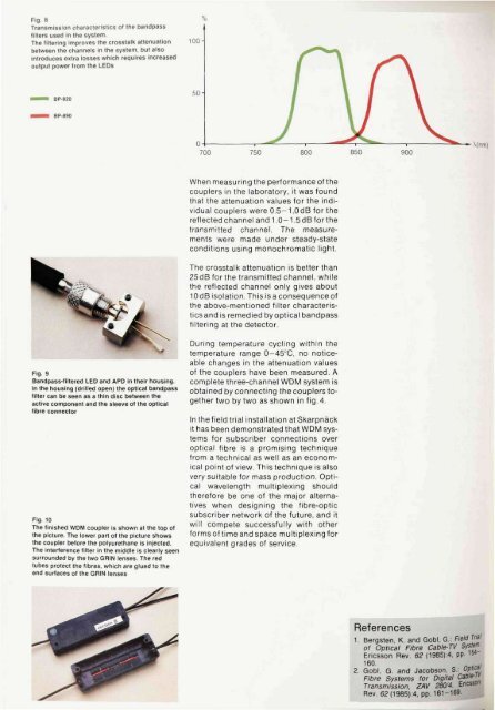
Fig. 8<br />
Transmission characteristics <strong>of</strong> the bandpass<br />
filters used in the system.<br />
The filtering improves the crosstalk attenuation<br />
between the channels in the system, but also<br />
introduces extra losses which requires increased<br />
output power from the LEDs<br />
100-<br />
%<br />
BP-820<br />
50<br />
BP-890<br />
700 750 800 850 900<br />
\(nm)<br />
When measuring the per<strong>for</strong>mance <strong>of</strong> the<br />
couplers in the laboratory, it was found<br />
that the attenuation values <strong>for</strong> the individual<br />
couplers were 0.5-1,0 dB <strong>for</strong> the<br />
reflected channel and 1.0-1.5 dB <strong>for</strong> the<br />
transmitted channel. The measurements<br />
were made under steady-state<br />
conditions using monochromatic light.<br />
The crosstalk attenuation is better than<br />
25 dB <strong>for</strong> the transmitted channel, while<br />
the reflected channel only gives about<br />
10 dB isolation. This is a consequence <strong>of</strong><br />
the above-mentioned filter characteristics<br />
and is remedied by optical bandpass<br />
filtering at the detector.<br />
Fig. 9<br />
Bandpass-filtered LED and APD in their housing.<br />
In the housing (drilled open) the optical bandpass<br />
filter can be seen as a thin disc between the<br />
active component and the sleeve <strong>of</strong> the optical<br />
fibre connector<br />
Fig. 10<br />
The finished WDM coupler is shown at the top <strong>of</strong><br />
the picture. The lower part <strong>of</strong> the picture shows<br />
the coupler be<strong>for</strong>e the polyurethane is injected.<br />
The interference filter in the middle is clearly seen<br />
surrounded by the two GRIN lenses. The red<br />
tubes protect the fibres, which are glued to the<br />
end surfaces <strong>of</strong> the GRIN lenses<br />
During temperature cycling within the<br />
temperature range 0-45°C, no noticeable<br />
changes in the attenuation values<br />
<strong>of</strong> the couplers have been measured. A<br />
complete three-channel WDM system is<br />
obtained by connecting the couplers together<br />
two by two as shown in fig. 4.<br />
In the field trial installation at Skarpnäck<br />
it has been demonstrated that WDM systems<br />
<strong>for</strong> subscriber connections over<br />
optical fibre is a promising technique<br />
from a technical as well as an economical<br />
point <strong>of</strong> view. This technique is also<br />
very suitable <strong>for</strong> mass production. <strong>Optical</strong><br />
wavelength multiplexing should<br />
there<strong>for</strong>e be one <strong>of</strong> the major alternatives<br />
when designing the fibre-optic<br />
subscriber network <strong>of</strong> the future, and it<br />
will compete successfully with other<br />
<strong>for</strong>ms <strong>of</strong> time and space multiplexing <strong>for</strong><br />
equivalent grades <strong>of</strong> service.<br />
References<br />
1. Bergsten, K. and Gobi, G: <strong>Field</strong> <strong>Trial</strong><br />
<strong>of</strong> <strong>Optical</strong> <strong>Fibre</strong> <strong>Cable</strong>-<strong>TV</strong> Systern.<br />
Ericsson Rev. 62 (1985):4, pp. W<br />
160. . ,<br />
2. Gobi, G. and Jacobson, S.: 0P" c JJ<br />
<strong>Fibre</strong> <strong>System</strong>s <strong>for</strong> Digital <strong>Cable</strong>-1*<br />
Transmission, ZAV 280/4. Ericsson<br />
Rev. 62(1985):4, pp. 161-169.


