

Field Trial of Optical Fibre Cable-TV System Optical Fibre System for ...
Field Trial of Optical Fibre Cable-TV System Optical Fibre System for ...
Field Trial of Optical Fibre Cable-TV System Optical Fibre System for ...

Create successful ePaper yourself
Turn your PDF publications into a flip-book with our unique Google optimized e-Paper software.
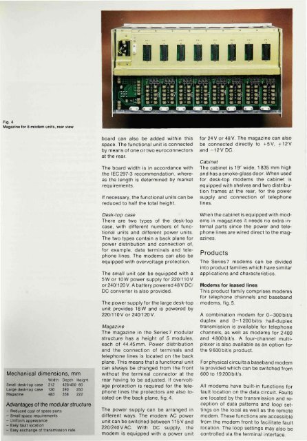
Fig. 4<br />
Magazine <strong>for</strong> 8 modem units, rear view<br />
Mechanical dimensions, mm<br />
Width Depth Height<br />
Small desk-top case 212 420/450 60<br />
Large desk-top case 130 390 250<br />
Magazine 483 358 222<br />
Advantages <strong>of</strong> the modular structure<br />
- Reduced cost ol spare parts<br />
- Small space requirements<br />
- Uni<strong>for</strong>m appearance<br />
- Easy fault location<br />
- Easy exchange <strong>of</strong> transmission rate<br />
board can also be added within this<br />
space. The functional unit is connected<br />
by means <strong>of</strong> one or two euroconnectors<br />
at the rear.<br />
The board width is in accordance with<br />
the IEC297-3 recommendation, whereas<br />
the length is determined by market<br />
requirements.<br />
If necessary, the functional units can be<br />
reduced to half the total height.<br />
Desk-top case<br />
There are two types <strong>of</strong> the desk-top<br />
case, with different numbers <strong>of</strong> functional<br />
units and different power units.<br />
The two types contain a back plane <strong>for</strong><br />
power distribution and connection <strong>of</strong>,<br />
<strong>for</strong> example, data terminals and telephone<br />
lines. The modems can also be<br />
equipped with overvoltage protection.<br />
The small unit can be equipped with a<br />
5W or 10 W power supply <strong>for</strong> 220/110 V<br />
or 240/120 V. A battery powered 48 V DC/<br />
DC converter is also provided.<br />
The power supply <strong>for</strong> the large desk-top<br />
unit provides 18W and is powered by<br />
220/110 V or 240/120 V.<br />
Magazine<br />
The magazine in the Series7 modular<br />
structure has a height <strong>of</strong> 5 modules,<br />
each <strong>of</strong> 44.45 mm. Power distribution<br />
and the connection <strong>of</strong> terminals and<br />
telephone lines is located on the back<br />
plane. This means that a functional unit<br />
can always be changed from the front<br />
without the terminal connector at the<br />
rear having to be adjusted. If overvoltage<br />
protection is required <strong>for</strong> the telephone<br />
lines the protectors are also located<br />
on the back plane, fig. 4.<br />
The power supply can be arranged in<br />
different ways. The modem AC power<br />
unit can be switched between 115 V and<br />
220/240VAC. With DC supply, the<br />
modem is equipped with a power unit<br />
<strong>for</strong> 24 V or 48V. The magazine can also<br />
be connected directly to +5V, +12V<br />
and -12V DC.<br />
Cabinet<br />
The cabinet is 19" wide, 1 835 mm high<br />
and has a smoke-glass door. When used<br />
<strong>for</strong> desk-top modems the cabinet is<br />
equipped with shelves and two distribution<br />
frames at the rear, <strong>for</strong> the power<br />
supply and connection <strong>of</strong> telephone<br />
lines.<br />
When the cabinet is equipped with modems<br />
in magazines it needs no extra internal<br />
parts since the power and telephone<br />
lines are wired direct to the magazines.<br />
Products<br />
The Series7 modems can be divided<br />
into product families which have similar<br />
applications and characteristics.<br />
Modems <strong>for</strong> leased lines<br />
This product family comprises modems<br />
<strong>for</strong> telephone channels and baseband<br />
modems, fig. 5.<br />
A combination modem <strong>for</strong> 0-300bit/s<br />
duplex and 0-1200bit/s half-duplex<br />
transmission is available <strong>for</strong> telephone<br />
channels, as well as modems <strong>for</strong> 2400<br />
and 4800bit/s. A four-channel multiplexer<br />
is also available as an option <strong>for</strong><br />
the 9600 bit/s product.<br />
For physical circuits a baseband modem<br />
is provided which can be switched from<br />
600 to 19 200 bit/s.<br />
All modems have built-in functions <strong>for</strong><br />
fault location on the data circuit. Faults<br />
are located by the transmission and reception<br />
<strong>of</strong> data patterns and loop settings<br />
on the local as well as the remote<br />
modem. These functions are accessible<br />
from the modem front to facilitate fault<br />
location. The loop settings may also be<br />
controlled via the terminal interface.


