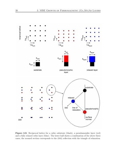
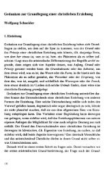
38 3. MBE Growth of <strong>Ferromagnetic</strong> (<strong>Ga</strong>,<strong>Mn</strong>)<strong>As</strong> <strong>Layers</strong> Figure 3.9: Reciprocal lattice for a cubic substrate (black), a pseudomorphic layer (red) <strong>and</strong> a fully relaxed cubic layer (blue). The lower half shows a combination of the above three cases, the zoomed section corresponds to the (044) reflection with the triangle of relaxation.
3.5. X-Ray Diffraction 39 lattice direction by measuring a reflection that is sensitive to only one in-plane lattice direction, such as for example (206). A map of the reciprocal space is assembled by a number of line scans along a scan axis. Each such scan is offset by a small step in a second axis, called the area axis. Possible choices for these axes are ω, 2Θ, <strong>and</strong> ω-2Θ. The best choice of axes depends on the specific reflection <strong>and</strong> the area which needs to be measured. Usually it is a pair of axes which most efficiently spans a reciprocal space area containing the whole region of interest. Reciprocal Lattice Units A RSM is usually depicted as a 2D cut plane in reciprocal space. The coordinates in a RSM have a component perpendicular to the sample surface q ⊥ <strong>and</strong> a component parallel to the surface q ‖ . For the scaling of RSMs, we use reciprocal lattice units (r.l.u.), a dimensionless representation of rational Miller indices (hkl) with respect to the Miller indices of the substrate. For a layer where both in-plane directions h <strong>and</strong> k are equal, the conversion between the reciprocal lattice constant q <strong>and</strong> the real space lattice constant a is given by: ⎛ ⎞ ⎛ ⎞ ⎛ q ‖ h ⎝q ‖ ⎠ = ⎝k⎠ ⎜ · ⎝ q ⊥ l a sub ⎞ a ‖ a sub ⎟ a ‖ a sub a ⊥ ⎠ (3.8) With this equation it is immediately possible to relate a reciprocal space peak position measured in r.l.u. with a real space in-plane <strong>and</strong> perpendicular-to-plane lattice constant for a given reflection. With this relation <strong>and</strong> the information from Fig. 3.9, it is also easy to calculate the corners of the relaxation triangle, see table 3.1. Table 3.1: Reciprocal space coordinates for the corner points of a relaxation triangle of an epitaxial layer. For a <strong>Ga</strong><strong>As</strong> substrate, a sub = 5.6533 Å. position real space reciprocal space (q ‖ , q ⊥ ) substrate a ‖ = a ⊥ = a sub (h, l) pseudomorphic a ‖ = a sub , a ⊥ = a vert (h, l · asub relaxed a ‖ = a ⊥ = a layer a (h · sub a layer , l · a vert ) a sub a layer ) Example of RSM To illustrate the application of a RSM, we present the measurement on a <strong>Ga</strong><strong>As</strong>/ (In,<strong>Ga</strong>)<strong>As</strong>/(<strong>Ga</strong>,<strong>Mn</strong>)<strong>As</strong> structure. The goal of this sample was to achieve an out of plane easy axis of the magnetization, as described in Chapter 1, by growing (<strong>Ga</strong>,<strong>Mn</strong>)<strong>As</strong> under tensile strain. To achieve this strain situation, the (In,<strong>Ga</strong>)<strong>As</strong> layer was grown to a thickness of 1 µm, to allow plastic relaxation of the layer, <strong>and</strong> thereby forming a substrate for the (<strong>Ga</strong>,<strong>Mn</strong>)<strong>As</strong> layer with a larger lattice constant than the relaxed lattice constant of (<strong>Ga</strong>,<strong>Mn</strong>)<strong>As</strong>.