Ferromagnetic (Ga,Mn)As Layers and ... - OPUS Würzburg
Ferromagnetic (Ga,Mn)As Layers and ... - OPUS Würzburg
Ferromagnetic (Ga,Mn)As Layers and ... - OPUS Würzburg

Create successful ePaper yourself
Turn your PDF publications into a flip-book with our unique Google optimized e-Paper software.
48 4. Finite Element Simulations of Strain Relaxation<br />
region 1 region 2<br />
region 3<br />
z<br />
y<br />
unstructured <strong>Ga</strong><strong>As</strong><br />
structured <strong>Ga</strong><strong>As</strong><br />
structured (<strong>Ga</strong>,<strong>Mn</strong>)<strong>As</strong><br />
x<br />
z<br />
z = h sub + h a + h mn<br />
surface 4<br />
z = h sub + h a<br />
region 3<br />
surface 3<br />
z = h sub<br />
region 2<br />
surface 2<br />
z = 0<br />
y<br />
x<br />
region 1<br />
surface 1<br />
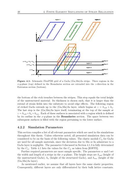
Figure 4.1: Schematic FlexPDE grid of a <strong>Ga</strong><strong>As</strong>/(<strong>Ga</strong>,<strong>Mn</strong>)<strong>As</strong> stripe. Three regions in the<br />
x-y-plane (top) defined in the Boundaries section are extended into the z-direction in the<br />
Extrusion section (bottom).<br />
the bottom of the etch trenches between the stripes. This step equals the total height<br />
of the unstructured material. Its thickness is chosen such, that it is larger than the<br />
extend of strain fields into the substrate to avoid edge effects. The following region<br />
of etched <strong>Ga</strong><strong>As</strong> extends up to the (<strong>Ga</strong>,<strong>Mn</strong>)<strong>As</strong> layer, which begins at z = h sub + h a .<br />
The last step is the (<strong>Ga</strong>,<strong>Mn</strong>)<strong>As</strong> layer itself, terminating at the top of the sample at<br />
z = h sub + h a + h mn . Each of these surfaces is associated with a region which is defined<br />
by its outline in the x-y-plane in the Boundaries section. The space between two<br />
subsequent surfaces is filled with the region pertaining to the lower surface.<br />
4.2.2 Simulation Parameters<br />
This section compiles a list of all relevant parameters which are used in the simulations<br />
throughout this thesis. Unless otherwise noted, all presented simulation data can be<br />
considered to be on the basis of the following values. The elastic moduli C ij for <strong>Ga</strong><strong>As</strong><br />
are used for all sample materials, since the deviation due to <strong>Mn</strong> or In admixture to a<br />
<strong>Ga</strong><strong>As</strong> layer is negligible. The parameter b discussed in Section 4.1.3 is fully determined<br />
by the C ij . Table 4.1 lists the values for the C ij as taken from [IOFFE].<br />
Further required parameters are more sample specific. The parameters w <strong>and</strong> l set<br />
the width <strong>and</strong> length of a stripe in the x-y-plane. The height steps are h sub (height of<br />
the unstructured <strong>Ga</strong><strong>As</strong>), h a (height of the structured <strong>Ga</strong><strong>As</strong>), <strong>and</strong> h mn (height of the<br />
(<strong>Ga</strong>,<strong>Mn</strong>)<strong>As</strong> layer).<br />
<strong>As</strong> mentioned earlier, we assume that all layers have the same elastic properties.<br />
Consequently, different layers are only differentiated by their bulk lattice constants.