Elementele componente ale reţelei Petri: Locaţii: P1 ... - IPA SA
Elementele componente ale reţelei Petri: Locaţii: P1 ... - IPA SA
Elementele componente ale reţelei Petri: Locaţii: P1 ... - IPA SA

You also want an ePaper? Increase the reach of your titles
YUMPU automatically turns print PDFs into web optimized ePapers that Google loves.
REVISTA ROMÂN DE AUTOMATIC<br />
119<br />
medium. The taken signals are used for<br />
permanent monitoring of the functioning<br />
of the electrical distribution station.<br />
Synchronous acquisition, on a<br />
determined period of time, of a set of<br />
characteristic parameters of the transient<br />
regime when an error occurs in the<br />
monitored electrical station. The set of<br />
data stored during the error period is then<br />
sent to a computer where the interpretation<br />
of data is done by the help of a dedicated<br />
program.<br />
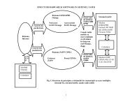
2. The architecture of the monitoring<br />
System<br />
To accomplish the two main directions, there<br />
was designed a complex data acquisition, data<br />
sending and receiving system [5], [7], [8], which<br />
has the block diagram presented in Fig.1.<br />
The system functions must provide:<br />
permanent and real time visualization of<br />
the characteristic measures for the electrical<br />
station (currents, voltages, powers, energy,<br />
power factors, auxiliary contacts);<br />
visual and sound alarm in case of<br />
outrunning pre-established range for any of<br />
the monitored measures;<br />
visual and sound alarm in case any<br />
equipment faults (fails of communication<br />
lines, fails of data collecting equipments,<br />
etc.);<br />
recording information into a database<br />
(dispatcher), assuring the possibility to<br />
process data on the network server computer<br />
or on any workstation connected to the<br />
network;<br />
graphical display of the measures taken<br />
from the process, on time periods defined by<br />
the users;<br />
printing of consumption diagrams and<br />
specific diagrams on time periods defined by<br />
the user;<br />
interconnection into a computer network;<br />
data transfer to a central dispatcher.<br />
2.1 Processing, storing and data<br />
displaying subsystem<br />
This subsystem is composed of an IBM–PC<br />
compatible computer and the corresponding<br />
software which allows storing, processing,<br />
displaying and printing data taken from a<br />
maximum number of 255 local data<br />
acquisition equipments (LDAqE) from<br />
electrical cells. This computer can be<br />
integrated in a LAN at the dispatcher level,<br />
allowing data access to authorized users.<br />
2.2 Data communication subsystem<br />
This subsystem is composed of equipments<br />
for connecting to the optical fiber<br />
environment (equipment at the dispatcher’s<br />
level and equipment for each of the electrical<br />
cell from the perimeter of the supervised<br />
station) which assure communication at high<br />
speed and high security between the data<br />
processing subsystem and the local data<br />
acquisition equipments.<br />
The proposed subsystem is immune to the<br />
electromagnetic interferences and assures<br />
optimal galvanic isolation between the<br />
acquisition equipments and the equipments<br />
form the dispatcher.