Part II - IPA SA
Part II - IPA SA
Part II - IPA SA

You also want an ePaper? Increase the reach of your titles
YUMPU automatically turns print PDFs into web optimized ePapers that Google loves.
RRA, Vol. XX, Nr. 3 - 4 pag. 29-36, 2007 Tiprit în România<br />
VIREC, A VIRTUAL ROBOT CENTER FOR E-LEARNING<br />
eng. Alexandru CRACIUN<br />
<strong>IPA</strong>, Craiova subsidiary, Romania, e_mail: office@ipacv.ro<br />
eng. Cornelia POPA<br />
<strong>IPA</strong>, Craiova subsidiary, Romania, e_mail: office@ipacv.ro<br />
eng. Daniela MIHAI<br />
<strong>IPA</strong>, Craiova subsidiary, Romania, e_mail: office@ipacv.ro<br />
eng. Mircea BADEA<br />
<strong>IPA</strong>, Craiova subsidiary, Romania, e_mail: office@ipacv.ro<br />
Abstract: In the technological field, virtual reality technology has been widely proposed and recognized<br />
as a major technological advance for supporting life-long education to individuals along with a flexible<br />
workforce. One of the unique capabilities of the VR technology is the successful translation of abstract concepts<br />
into visualized events and the interaction of students with them, that in real life could be limited due to distance,<br />
time, and safety factors. This paper presents a virtual laboratory ViReC accessible through the Internet. The<br />
architecture uses open standards, such as World Wide Web and its related technologies: HTTP, HTML, Java,<br />
Macromedia Flash, PHP, MySQL and so on.<br />
Keywords: Virtual robotics, Virtual laboratory, E-learning, Internet solutions.<br />
l. INTRODUCTION<br />
The wide expansion of the World Wide Web<br />
and the Internet has formed all the necessary<br />
preconditions for adopting this powerful<br />
means for purposes such as delivery of E-<br />
learning content, collaboration and distance<br />
learning, both in the industrial and the<br />
educaional field.<br />
E-learning can also be very useful in the case of<br />
a potenial public for learning that could be<br />
described as "itinerant or that is widely<br />
scattered over a vast area" (Hamburg ei al,<br />
2003a). E-learning may be a way of<br />
overcoming geographical isolation and physical<br />
distances from resources or learning<br />
canters. In these situations, the use of the<br />
Internet and network-king takes on its full<br />
meaning. Robotics is well suited as a problem<br />
domain because it intrinsically requires<br />
multidisciplinary knowledge. Robotics<br />
encompasses subjects such as mechanical<br />
engineering, electronics, control,<br />
communication, vision, real-time parallel<br />
computing and systems design. By choosing<br />
a problem domain with a high multi-disciplinary<br />
requirement, we reduce the chance that any<br />
one person on the team will "cheat" and do all<br />
the work.As the literature supporting the positive<br />
educaional effects of robotics accumulates, it<br />
becomes increa-singly clear that:<br />
• Robotics is very absorbing and enjoyable<br />
for many children and adults<br />
• Robotics events and competitions<br />
motivate the study of technical subjects<br />
• Robotics provides hands on examples<br />
for teaching science, technology,<br />
engineering<br />
• Robotics creates excellent possibilities<br />
for learning team working, especially<br />
through competitions.<br />
Cumulative experience suggests that robotics<br />
is an excellent domain for introducing<br />
students to a range of technological and<br />
scientific disciplines. Robotics provides<br />
leverage on two key pedagogic aims of E-<br />
learning: problem-based learning and engaging<br />
students in discourse (i.e. creating a<br />
community of learning). So, robotics
30 REVISTA ROMÂN DE AUTOMATIC<br />
possesses a number of specifics advantages<br />
that make it particularly well suited to<br />
unsupervised project work at a distance.<br />
Distance learners often have little opportunity<br />
for face-to-face contact, although some<br />
courses offer up to two hour-long monthly<br />
tutorials or one-off day schools. However,<br />
attendance at such tutorials is not compulsory<br />
and there are many reasons why distance<br />
education students may be unable to attend<br />
meetings.<br />
2. MOTIVATIONS AND DESIGN<br />
The main motivation factors that inspired the<br />
design and the implementation of the ViReC<br />
and the goal that should be achieved by this<br />
work is threefold:<br />
• To provide an E-learning environment<br />
for students as well as to overcome<br />
communication difficulties among them<br />
• To overcome limitations of current E-<br />
learning applications<br />
• To avoid limitations met in most<br />
Virtual Robot applications so far.<br />
• At a first level we plan to support the<br />
community of Virtual Laboratory users<br />
as follows:<br />
• To overcome the problem of interaction<br />
and communication among them<br />
• To support the students to construct<br />
their knowledge in a "learning by<br />
doing" situation<br />
• To provide remote support to students<br />
by mentors.<br />
The ViRec source of inspiration was a real<br />
robotized application for didactical purpose<br />
(Niulescu et al, 2002), developed into the<br />
Robotics laboratory of the University of<br />
Craiova, Faculty of Automation, Computere<br />
and Electronics (Figure 1). The principally<br />
components of the overall structure are an<br />
ABB IRB 1400 robot (1) and a multifunction<br />
didactical plat-form (2), containing five<br />
stations.<br />
Fig. 1 The real platform for robotized application<br />
3. ARCHITECTURE AND<br />
IMPLEMENTATION<br />
This section is dedicated to describing the<br />
structure of the system that supports the<br />
ViReC. The term structure is used for<br />
referring to the logical view of the static<br />
structure of the architecture in terms of its<br />
components, their interconnections and the<br />
inter-faces and operations offered by these<br />
components.<br />
The step that follows the definition of the<br />
main design principles of the Virtual Robot is<br />
the assess-ment of the technologies that will<br />
facilitate the implementation of the system.<br />
The system should be an easily accessible<br />
web-based system, used by a worldwide<br />
community, taking into account band-width,<br />
and client-side system constraints. Therefore<br />
one of the major targets apart from<br />
implementing the Virtual Robot with the<br />
appropriate functionality is to satisfy the<br />
following prerequisites. First, there is a need<br />
to minimize the client-side system<br />
requirements and the cost of client-side<br />
system set-up. This means that the end-user<br />
should be able to access the laboratory using<br />
a typical personal computer without<br />
excessive requirements either in hardware or<br />
in software. Second, the system should have<br />
the ability to support a maximum number of<br />
simultaneous users. This requirement should<br />
in particular be considered in the multi-user<br />
applications. Finally, using technologies,
REVISTA ROMÂN DE AUTOMATIC<br />
31<br />
which do not require excessive hardware<br />
requirements, should also minimize the cost<br />
of the server side set-up. As far as it concerns<br />
the web server, it is used for storing the<br />
client-side files of the Virtual Robot, voice<br />
chat and text chat. Furthermore, the web<br />
server stores and executes the PHP scripts to<br />
obtain the users' data from a database. The<br />
web server that satisfies these prerequisites is<br />
the Apache web server, which is free of<br />
charge, runs on almost all operating systems,<br />
supports PHP scripts, can host Director and<br />
Flash movies and can interoperate with<br />
MySQL, Macromedia Flash Communication<br />
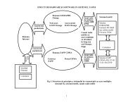
Server MX and Java. The internal structure of<br />
the Virtual Robot Center is presented in<br />
Figure 2.<br />
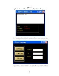
As Figure 3 shows, the basic graphical user<br />
interface GUI of ViReC contain 5 topics<br />
(links): Docs, Tutorial, Exercises, Online<br />
Support and Plugins. It can be downloaded<br />
from our site http://www.ipacv.ro<br />
/proiecte/robotstudio/index.<br />
Fig. 4. The GUI interface for the topics ”Docs”<br />
Fig.2. The structure of the Virtual Robot Center<br />
Fig. 3. The initial starting GUI interface of ViReC<br />
The "Docs" topics presents basics<br />
information for the user. Before using the<br />
compiler, it is necessary for any user to<br />
enrich his knowledge by reading about the<br />
robot controller, the robot programming<br />
language and communication protocols, how<br />
to make a module or a routine, how to<br />
combine them into a program, how to read<br />
and analyze the programming instruct-tions<br />
and the complete examples presented in this<br />
section. The information is enough in order to<br />
offer support for a user with medium skills in<br />
this domain. Because the use and the<br />
programming is limited by the real robot<br />
operaional space, the user has to know more<br />
information about: the coordinates of robot<br />
movement, the position of the table with<br />
pneumatic devices which are placed facing<br />
the robot, the pieces type and their position<br />
on the table, the buffers where the raw pieces<br />
are gathered and the way the pneumatic<br />
extractors act. This section also presents the<br />
most useful instructions of programming (for<br />
moving, for activating and deactivating<br />
sensors, for logical, arith-metic, assigning,<br />
conditioning, looping, selection etc), together<br />
with examples of programs. A<strong>II</strong> these<br />
information (Figure 4) are gruped in the<br />
folowing 10 chapters: Basic Characteristics<br />
(including the sections: Modules, Routines,
32 REVISTA ROMÂN DE AUTOMATIC<br />
Data Types, Data, Instructions, Expressions,<br />
Error Recovery, Interrupts, Back-ward<br />
Execution and Multitasking), Sample<br />
Applications (including sections: Assembling<br />
pieces, Para-lelipipedical pieces palletizing,<br />
Cylindrical pieces palletizing and Welding<br />
operation), Robot Motion, Servo System,<br />
Robot Structure, Manipulator, Teach<br />
Pendant, Controller, Communication<br />
Protocols and Application Environment.<br />
For example, the chapter "Sample<br />
Applications" presents simulated and interactive<br />
applications with basic operations: palletizing of<br />
two types of pieces (a parallelepipedical piece<br />
and a cylindrical piece), the assembling of these<br />
two types of pieces and the welding-line and<br />
welding-point operations in an attractive and<br />
explicit form for the reader. The user can<br />
analyze the instructions in the program during its<br />
execution and the way of activating and<br />
deactivating the sensors used in the run process.<br />
So, the user can stop the execution and even<br />
run step by step the execution in order to<br />
understand how the program is created. In these<br />
tutorials we can also find interactive applications<br />
with the user where he can choose the type of<br />
the piece that needs to be transformed and the<br />
place on the pallet where the piece is going to<br />
be placed. He can also analyze the instructions<br />
in the program and the activating and<br />
deactivating the sensors during its execution<br />
(Comsa et al, 2003).<br />
Fig. 5 The GUI interface for the topics “Tutorial”<br />
The "Tutorial" topics (Figure 5) presents 5<br />
chapters: Robot Tutorials, Assignment Labs,<br />
Simulate & Interactive application, Robot<br />
Movies and Help. Each of these chapters<br />
contains other sections. For example, the chapter<br />
Robot Tutorials presents dyna-mic on-line<br />
tutorials for robot axes in 3D graphic, a tutorial<br />
dealing with the buttons of the Teach Pendant for<br />
programming the robot in an attractive and<br />
explicit form, and an interactive presentation<br />
with the Teach Pendant joystick for the user. To<br />
offer useful information, this topics presents so a<br />
film with the execution in the real lab (Figure 1)<br />
and with information about the application<br />
components. We can also learn about how to<br />
integrate a module into a program, about the set<br />
of useful instructions in an explicit presentation<br />
with sound, images and examples of execution<br />
of linear and circular movement instructions in a<br />
3D form and so, the assignment of values in a<br />
variable. The lab assignments are presen-ted<br />
explicitly with sound and images for the user to<br />
understand the theme. The lab assignments are:<br />
• Movement operation (by moving the tool of<br />
robot from Home position to a specified point)<br />
• Output signals (set and reset output signals<br />
using RAPID instructions)<br />
• Simple palletizing operation (by grabbing a<br />
piece and move it to a specified position)<br />
• Palletizing operation (by grabbing the pieces<br />
and move its on specified positions)<br />
• The assembling operations (by assembling<br />
these two types of pieces we will obtain a new<br />
product. Flowing from the parallelepipedical<br />
pieces is supplied by the first two workstations<br />
and flowing of the cylindrical pieces from the<br />
last two workstations. All the pieces must be<br />
placed in specific positions, knowns by the<br />
robot. This two types of pieces are taken one by<br />
one by the robot and placed into the assembling<br />
place. Because of position's errors, it's<br />
necessary for the robot to do two supplementary<br />
movements to arrange all the pieces on the<br />
assembling place. After that, the robot puts the<br />
new product in a matricial storehouse with four<br />
locations.<br />
• The palletizing operation of<br />
parallelepipedical pieces (all the pieces must<br />
be placed successively in a matricial<br />
storehouse with four locations).
REVISTA ROMÂN DE AUTOMATIC<br />
33<br />
• Palletizing cylindrical pieces (flowing of the<br />
cylindrical pieces is supplied by the<br />
workstation number three and workstation<br />
number four. All the pieces must be placed in a<br />
matricial storehouse with eight locations.<br />
• The welding operation (to do this operation<br />
we use storehouses (or Station) 1 and 2, which<br />
are supplied with parallelepipedical pieces. The<br />
robot take these pieces one by one and puts them<br />
together in the assembling place. After that, with<br />
a welding device that is taken from the special<br />
support created for the welding device, the robot<br />
simulates welding-line and welding-point<br />
operations. When the operation is finished, the<br />
robot puts in the support the welding device and<br />
the piece in the matricial storehouse with four<br />
locations (in order 1, 2, 3, 4).<br />
There are also presented programming<br />
examples for the applications of palletizing,<br />
assembling and welding. They differ from the<br />
lab assignments by the positioning of the<br />
pieces in another order.<br />
Activating the section Robot Movies, the user<br />
can see a set of 4 movies with the real robot<br />
applications (Cylindrical Palletizing,<br />
Paralelipipedical Palletizing, Welding,<br />
Assembling).<br />
In the chapter "Help", the section Robot's<br />
Workplace is intended to provide a simulation<br />
tool in which the user can preview his written<br />
programs. After successfully loading the<br />
operating environment and the program to<br />
execute, just pushing the RUN button (Figure 6)<br />
will start the program simulation, current<br />
instruction being shown on screen. For greater<br />
customization, the user can define it's own<br />
environment space, containing various objects<br />
defined inside the editor. Those objects can<br />
have different proper-ties, like a piston that<br />
makes a push operation or a parallelepiped<br />
piece with/without holes.<br />
Fig. 6 The GUI interface for the topics ”Simulation”<br />
The third topics presented in the ViReC GUI is<br />
"Exercises". The user opens this window in<br />
the same time with the compiler and can edit<br />
a program. Once the program edited, the user<br />
opens the option "Run" of the compiler (Figure<br />
7) to see if the program has or has not errors.<br />
Fig. 7 The GUI interface for the compiler<br />
If errors are observed in the program, the<br />
compiler shows in a bottom window the number<br />
of the line in the program where the error is and<br />
helping explana-tions to make it right. The<br />
running of the program can be made slowly or<br />
step by step. The user can stop the execution and<br />
can pass to the next line, before the iniial line, or<br />
can continue the execution from the iniial line,<br />
if wanted. During the running of the program<br />
the user can visualize the stocked values in<br />
registers. It can be monitoring the activating and<br />
deactivating of some inputs and outputs pressing<br />
the number of the output that needs to be<br />
visualized. After the program being checked
34 REVISTA ROMÂN DE AUTOMATIC<br />
for errors, the execution can be seen by pressing the<br />
soft button "View Result". After pushing this<br />
button, a window in which the execution is<br />
visualized in 2D graphics is opened. The<br />
execution can be visualize from any angle by<br />
a simple rotating of the mouse.<br />
The last two topics presented in the GUI<br />
interface, "Online Support" and "Plugins", are<br />
introduced to offer auxiliary E-facilities for a<br />
user: chat, links to on-line appropriate<br />
courses or software.<br />
4. TECHNICAL DESCRIPTION OF<br />
ViReC<br />
Concerning the software support using to<br />
create the site ViReC, we can note in brief:<br />
• DataBase. MySQL is an open source<br />
relaional database management system<br />
(RDBMS) that uses Structured Query<br />
Language (SQL), the most popular language<br />
for adding, accessing, and processing data in<br />
a database.<br />
• Compiler. The compiler is developed<br />
using Java technology. An applet is a small<br />
Internet-based program written in Java, a<br />
programming language for the Web, which<br />
can be downloaded by any computer. The<br />
applet is also able to run in HTML. The<br />
applet is usually embedded in an HTML page<br />
on a Web site and can be executed from<br />
within a browser. Each user can save his<br />
work in database with public and private<br />
access. Software offer possibility to load<br />
components in environment to develop more<br />
applications.<br />
5. SOME TECHNICAL DETAILS<br />
The code behind simulation is made as<br />
follows:<br />
• iniial ization code<br />
• run-time code<br />
• clean-up code<br />
In the initialization phase, there are two<br />
different operations. First, the corresponding<br />
operating environment is read from the robot<br />
database. This is done through a service<br />
based on Apache Web server and PHP<br />
scripting language with MySQl Support.<br />
Below is shown how the operating<br />
environment is read using a sample script<br />
(getenv.php):<br />
//Make the database connection using Sdatabaseserver,<br />
Sdatabaseuser and Sdatabasepass variables<br />
Sconn =<br />
@mysql_connect($databaseserver,$databaseuser,$database<br />
pass);<br />
// Select the database<br />
Sdatabase = mysql_select_db($database,$conn);<br />
// The query text (Select all from the products table in our<br />
database)<br />
Sselect = "SELECT * FROM environment where<br />
user='$ POST[user]' and env='$ POSTfenv]'";<br />
// Make the query<br />
Sresult = mysql_query($select);<br />
// Count the rows (total result)<br />
$rows = mysql_num_rows($result);<br />
// For each result<br />
while($list = mysql_fetch_array($result)){<br />
// Set some variables, using the info get from the database<br />
// Slist is the array that contains the Db values<br />
// For example $list["id"] is the value of an 'id' field in the Db<br />
$id = $list["id"];<br />
Sobject = $list["object"];<br />
$x = $list["x"];<br />
$y = $list["y"];<br />
$z=$list["z"];<br />
//Prin in the browser window a string, in a format that Flash can read<br />
print("Total=$rows&Object$id=$object|$x|$y|$z&");<br />
} mysql_free_result($result);
REVISTA ROMÂN DE AUTOMATIC<br />
35<br />
In this way the objects from the environment<br />
are passed to the simulator, using the<br />
requested environment "$env" defined by<br />
user "$user". Then, the simulator decodes<br />
object data and interprets it for use. This is<br />
done in the root.onLoad function, which is<br />
called when the simulator loads.<br />
env = new LoadVars(); env.load("http://localhost/proiecte/robotstudio/getenv.php")<br />
env.onLoad = function (success)<br />
{ for (this.a = 1; this.a
36 REVISTA ROMÂN DE AUTOMATIC<br />
6. CONCLUSIONS<br />
Virtual laboratories represent now an<br />
important and modern educaional tools<br />
and solutions that bring together<br />
geographically distant research groups,<br />
allowing them to share data,<br />
documents, video and audio<br />
presentations, while integrating their<br />
computaional and laboratory<br />
resources. Among the many benefits of<br />
virtual laboratories, the foilowing are<br />
particularly very important:<br />
• Resource sharing becomes a reality,<br />
improving the utilization of costly<br />
equipment<br />
• Easier access to educaional and<br />
research material is provided to<br />
students and professional training<br />
courses<br />
• Scientific investigation standard<br />
can be esta-blished in areas where<br />
practicai experimentation is a required<br />
part of research<br />
• Reduction in travel time leads to<br />
productivity enhancement.<br />
The recent created virtual laboratories,<br />
as ViReC, are implemented as a new<br />
generation communication service, not<br />
as a simply Worldwide Web<br />
application. So, they employ a<br />
sophisticated access framework, a<br />
communication infrastructure able to<br />
support multimedia flows and a<br />
component-based<br />
software<br />
construction. As the Internet is turning<br />
into a truly multi-service network with<br />
a steady increase in bandwidth and<br />
decrease in response time, the<br />
environment becomes more suitable for<br />
implement-tations such as Virtual<br />
Laboratories.<br />
Furthermore, it offers various<br />
communication channels such as<br />
gestures, voice, and text chat, that help<br />
learners to interact and cooperate with<br />
each other.<br />
REFERENCES<br />
Coma C, M. Niulescu, R. Mitric and G. Vlâdu<br />
(2003). E-Laboratory solution for training in virtual<br />
robotics, Annals of the University of Craiova -<br />
Electrical and control engineering series, 27/1, pp.<br />
276-283.<br />
Hamburg I. (2003). Verteilt und doch gemeinsam<br />
lernen. In: Wissenschaftszentrum Nordrhein-<br />
Westfalen: Das Magazin, 14, H. 1, S. 34.<br />
Hamburg I., O. Cernian and T. Herbert (2003a).<br />
Blended learning and distributed learning environments.<br />
In: Proceedings of 5th International<br />
Conference on New Educaional Environments, pp.<br />
197-202, Lucerne, Switzerland.<br />
Hamburg I., O. Cernian and T. Herbert (2003b).<br />
Lernen und Kooperieren in verteilten Umgebungen:<br />
die Chance fur die betriebliche Weiterbildung!<br />
In: IT-basierte Lernformen fur die betriebliche<br />
Weiterbildung. Gelsenkirchen: Inst. Arbeit<br />
und Technik, S. 45-55.<br />
Niulescu M., A. Câpitnescu and C. Coma (2002).<br />
Integrarea robotului ABB IRB 1400 într-o celul<br />
flexibil de fabricaie cu scop didactic. In: Proc. of<br />
Conferina Naional de Robotic, pp. 155-160.<br />
http://news.bbc.co.Uk/l/hi/sci/tech/ll<br />
11654.stm.BBC News Article - Virtual Lab brings<br />
science to life.<br />
http://physicsweb.org/resources/Education/Interactiv<br />
e experiments/ physicsweb.org. Virtual Interak-tive<br />
Experiments.<br />
www.sci.brooklyn.cuny.edu/-marciano.Virtual<br />
Multi-Media Internet Laboratories.<br />
Waller J.C. and N. Foster (2000). Training via the<br />
web: a virtual instrument. In: Computers and<br />
Education, 35, pp. 161-167.<br />
AR934-7.doc
RRA, Vol. XX, Nr. 3 - 4 pag. 37-39, 2007 Tiprit în România<br />
Predictive Diagnostic and Supervision<br />
System for Hydroelectric Units<br />
Doru OPRISESCU<br />
SC <strong>IPA</strong> <strong>SA</strong>, Calea Floreasca 169, Bucuresti, Romania<br />
Apolodor GHEORGHIU<br />
SC <strong>IPA</strong> <strong>SA</strong>, Calea Floreasca 169, Bucuresti, Romania<br />
Georgeta GHEORGHIU<br />
SC <strong>IPA</strong> <strong>SA</strong>, Calea Floreasca 169, Bucuresti, Romania<br />
e-mail: ggheorghiu@ipa.ro<br />
Abstract: The early detection of an abnormal running tendency translates into substantial cost savings<br />
and additional production revenues.<br />
Keywords: Diagnose Platform Hydroelectric Units<br />
INTRODUCTION<br />
<strong>IPA</strong> <strong>SA</strong> has, since its founding in 1960,<br />
became a leader in process automation in all<br />
industrial branches, both in Romania and in<br />
the neighbourhoods countries or in the far<br />
eastern countries.<br />
This presentation refers to the monitoring<br />
and diagnosis system elaborated by <strong>IPA</strong> S.A.<br />
for the Movileni Hydroelectric Power Plant,<br />
containing two 6,5 kV and two 10,5 kV<br />
Kaplan hydroelectric units.<br />
Today, numerous pressures on the<br />
hydroelectric industry demand innovative<br />
new approaches to diagnosis and<br />
supervisions procedures, for early discovery<br />
of the abnormal running of the hydroelectric<br />
units.<br />
The solution is to form a separate team,<br />
whose activity shall concentrate upon the<br />
continuously monitoring of the hydroelectric<br />
power plant units, bringing together people,<br />
which are working for many years in the area<br />
of hydroelectric units maintenance and<br />
repairing.<br />
Consequently, the responsibility for this new<br />
activity have been allocated to a new operator:<br />
the operator of the monitoring and diagnosis<br />
system. This operator is advised in advance,<br />
by the diagnose system, of critical conditions,<br />
allowing effective decisions to be made to<br />
avoid or minimize the effects of an<br />
emergency.<br />
The PC Operator Stations related to this<br />
activity, were located in another room, near<br />
the plant Central Control Room.<br />
This separation between the two central rooms<br />
is very useful because the activity of the two<br />
kinds of operators is very different. The<br />
monitoring and diagnosis activity consists in<br />
the examination of the evolution in time of<br />
many parameters, apart from the plant control,<br />
which is carried on in real time.<br />
The early detection of an abnormal running<br />
tendency translates into substantial cost<br />
savings and additional production revenues.<br />
The diagnosis system implemented to<br />
Movileni hydroelectric plant uses all the<br />
process information able to concur to a<br />
complex analysis, as well as the more recent
38 REVISTA ROMÂN DE AUTOMATIC<br />
dedicated systems developed by<br />
acknowledged companies for the special<br />
monitoring domains such as vibrations and<br />
partial discharges.<br />
Consequently to this concept, the resulted<br />
system configuration, presented below,<br />
contains three PC based diagnosis stations,<br />
one for each diagnose domain:<br />
• DS1 for vibrations;<br />
• DS2 for partial discharges;<br />
• DS3 for other data.<br />
DS1<br />
DS2<br />
DS3<br />
U1 RS-485 / USB U2 RS-485 / RS-232<br />
RS-485<br />
RS-485<br />
RS-485<br />
Ethernet TCP/IP<br />
RS-485<br />
ABB<br />
Firewall<br />
Plant Server<br />
GROUP 1 & 2 GROUP 3 & 4<br />
ZOOM<br />
ZOOM<br />
GROUP 3 GROUP 4<br />
HydroTrac<br />
HydroTrac<br />
Sensors<br />
Sensors<br />
Capacitive<br />
couplers<br />
Capacitive<br />
couplers<br />
POWER PLANT<br />
CONTROL ROOM<br />
VIBRATIONS MONITORING<br />
All the components used for the vibrations<br />
monitoring as well as the components for the<br />
air gap monitoring was procured from<br />
VibroSyst M, a Canadian company.<br />
VibroSyst M Inc. [1] has, since its founding<br />
in 1986, become a leading manufacturer of<br />
monitoring and diagnostics systems that<br />
support condition-based maintenance of<br />
hydro generating units.<br />
The VibroSyst M diagnose software system,<br />
named “ZOOM” (Zero Outage On-line<br />
Monitoring) was adopted for monitoring and<br />
diagnostics acquisition of hydro generating<br />
units. The ZOOM System is easy to use,<br />
simplifies measurement procedures,<br />
facilitates behavior analysis and warns the<br />
user of alarm conditions.<br />
The ZOOM System database assures<br />
improved operations and maintenance of<br />
hydro generators, increasing its service<br />
availability and producing significant<br />
savings. The system represents an powerful<br />
analytical and diagnostic tool which:<br />
- Detect and diagnose anomalies to<br />
prevent forced outages;<br />
- Synchronized measurements for result<br />
correlation;<br />
- Simplified analysis process and<br />
improved diagnostic accuracy;<br />
- Stores all alarm for later event analysis<br />
and diagnosis.<br />
The VibroSist M system contains a lot of<br />
proximity probes mounted on the machines.<br />
These probes are connected, with special<br />
extension cables, to the programmable and<br />
monitoring units logged by <strong>IPA</strong> in two<br />
cabinets near the hydro generator units: one<br />
cabinet for group 1 and group 2 and another<br />
cabinet for group 3 and group 4. These two<br />
cabinets are connected via RS-485 network to<br />
the DS1 diagnosis station which is loaded<br />
with the ZOOM software.<br />
The monitoring refers to the shaft relative<br />
vibration, the bearing absolute vibration and<br />
the generator air gap correlated with a<br />
synchro probe.
REVISTA ROMÂN DE AUTOMATIC<br />
39<br />
PARTIAL DISCHARGE MONITORING<br />
All the components used for the <strong>Part</strong>ial<br />
Discharge (PD) monitoring, including<br />
capacitive couplers, HydroTrac units and<br />
special software, was procured from IRIS<br />
Power, a Canadian company. The <strong>Part</strong>ial<br />
Discharge system was used for two of the<br />
four hydro generators, the generators with a<br />
voltage of 10,5 kV.<br />
In 1994, IRIS [2] installed the world’s first<br />
commercial continuous on-line partial discharge<br />
measuring system for large generators.<br />
The IRIS HydroTrac system was released in<br />
2000. The <strong>Part</strong>ial Discharge testing has<br />
become the most pervasive tool for assessing<br />
the condition of the stator winding insulation<br />
during normal operation of a hydro generator.<br />
Typical winding aging condition, which can be<br />
detected by partial discharge testing, include:<br />
- loose wedges;<br />
- insulation delaminating;<br />
- separation of copper-insulation bond;<br />
- deterioration of semi-conducting<br />
coating;<br />
- damaged semi-conducting/grading<br />
coating overlap area;<br />
- cracks on winding insulation;<br />
- problems related to thermal,<br />
mechanical, and/or electrical aging of<br />
the insulation.<br />
The results of PD testing are generally<br />
summarized by two key indicators or<br />
summary numbers: NQN and Qm. These two<br />
factors are derived from the standard pulse<br />
height analysis plots obtained from a PD test.<br />
- NQN is the area under the pulse<br />
height analysis curve, and represent the total<br />
PD activity and indicate the increasing<br />
insulation aging.<br />
- Qm is the magnitude, in mV, of the<br />
largest PD pulses detected and is indicative of<br />
the worst deterioration within the machine.<br />
For each of the two 10,5kV hydro generator<br />
was allocated a HydroTrac unit. The two<br />
units were connected, via an RS-485 network,<br />
to the central DS2 diagnosis station.<br />
OTHER DATA MONITORING<br />
The other data, which were necessary to be<br />
monitored, are obtained from the SCADA<br />
system, elaborated by ABB Germany, via an<br />
OPC server – OPC client connection in which<br />
ABB is the server and <strong>IPA</strong> is the client.<br />
As OPC client, <strong>IPA</strong> has used the RSView32<br />
base software from the Rockwell Automation<br />
Company. The process parameters, which are<br />
taken over in this way, for analysis, are the<br />
following:<br />
• Hydro generator stator winding, iron<br />
core and bearing temperature;<br />
• Cooling water, cooling air and oil<br />
temperature;<br />
• Guide vane opening;<br />
• Grate clogging level;<br />
• Water upstream and downstream<br />
level;<br />
• Circuit breakers and protections<br />
state;<br />
• Voltage and current in the 0,4 kV<br />
circuits;<br />
• Oil and cooling water pumps<br />
running hours.<br />
These information are used to give, for<br />
example, a statistical image about the<br />
frequency of circuit breakers disconnecting or<br />
about how many times a winding temperature<br />
has exceed a certain value and at what time.<br />
All these data are archived, to be used for a<br />
long time diagnosis trend display, or to be<br />
edited in a printed report.<br />
REFERENCES<br />
[1] VibroSyst M “On line monitoring of<br />
hydro generating units for optimized<br />
operations and maintenance”.<br />
[2] B.A. Lloyd and G.C. Stone – Iris Power<br />
Engineering – “Experience with continuous<br />
on-line stator winding partial discharge<br />
monitoring of hydro generators”.<br />
AR934-8.doc
RRA, Vol. XX, Nr. 3 – 4 pag. 40-44, 2007 Tiprit în România<br />
Quality of the electric energy; measurement and analyse methods and system<br />
eng. Ciprian PREDESCU<br />
<strong>IPA</strong>, Craiova subsidiary, Romania, e_mail: office@ipacv.ro<br />
eng. Daniela MIHAI<br />
<strong>IPA</strong>, Craiova subsidiary, Romania, e_mail: office@ipacv.ro<br />
eng. Cornelia POPA<br />
<strong>IPA</strong>, Craiova subsidiary, Romania, e_mail: office@ipacv.ro<br />
eng. Irina CONSTANTINESCU<br />
<strong>IPA</strong>, Craiova subsidiary, Romania, e_mail: office@ipacv.ro<br />
eng. Alexandru CRCIUN<br />
<strong>IPA</strong>, Craiova subsidiary, Romania, e_mail: office@ipacv.ro<br />
Abstract: The paper presents the equipment used to measure some parameters that characterize the<br />
electric energy quality.<br />
The proposed equipment performs test and acquisition of analogue data (U and I) and numerical data.<br />
The sampled data are recorded when preset thresholds are exceeded by the analogical inputs or when<br />
the digital inputs states change. The fixed variant is supplementary provided with 2 analogue outputs<br />
and 8 numerical outputs. The operation of equipment is simulated and the corresponding software are<br />
exemplified for the case of a highly distorting consumer, a set of electric energy quality parameters<br />
being determined for this case.<br />
Keywords: Energy system management, Measurements, Transducers.<br />
1. INTRODUCTION<br />
The recent implementations based on power<br />
electronics provide a lot of advantages<br />
related to the designing of some high power<br />
electrical drives with variable speed, such as<br />
the increase of driving system<br />
performances. Unfortunately this kind of<br />
equipment added new quality problems to<br />
the existing ones. The new problems are<br />
related to the electric nature waveforms<br />
distortions, with direct impact over the<br />
consumers supplying.<br />
The energetic effects that affect the electric<br />
energy quality must be precisely evaluated<br />
in order to their consecutive limitation. The<br />
quality parameters measurement is related to<br />
the existing voltage level, to the data<br />
acquisition time speed, to the employed<br />
numeric algorithms. Test and isolated<br />
implementations were recently performed in<br />
our country and abroad, but none became a<br />
market leader.<br />
2. GENERAL DESCRIPTION EQUIPMENT<br />
In order to determine some of the electric<br />
energy quality parameters and also to achieve<br />
a complex equipment that should be able to<br />
determine some other quantities and<br />
unpleasant phenomena, a modular portable<br />
system was conceived. The main functions<br />
provided by it are:<br />
- determination of electric energy quality<br />
parameters that should consequently result in<br />
measures for improving of qualitative and<br />
quantitative efficiency of energetic<br />
consumptions;<br />
- events recording, in order to detect the<br />
faults causes and the repeated connections<br />
and disconnections over electric lines.
REVISTA ROMÂN DE AUTOMATIC<br />
41<br />
The equipment modular designing makes<br />
possible the realization of a family of fixed<br />
and portable systems for tests and data<br />
acquisitions. Due to its modular conceiving,<br />
the system provides:<br />
- acquisition of 9/16 analogue inputs and<br />
6/32 numerical inputs by means of circuits<br />
that perform the conditioning of analogue<br />
signals compatible to the electric quantities<br />
supplied by the electro-energetic systems;<br />
- portable variant will be supplementary<br />
equipped with 2 analogue outputs and 8<br />
numeric outputs for simulations, tunings and<br />
tests;<br />
- non-volatile recording of finite number of<br />
records;<br />
- connection through a serial line of a PC<br />
compatible computing system for data<br />
loading corresponding to the recordings that<br />
present interest.<br />
3. EQUIPMENT FUNCTIONS<br />
The equipment family provides the<br />
following functions:<br />
- test and acquisition of analogue data<br />
(voltages, currents and powers) and<br />
respectively of numeric data (switching<br />
apparatus state) for nodes of the electroenergetic<br />
system where the distorting<br />
regimes occur;<br />
- numeric processing of data, in order to<br />
determine the energetic parameters, the<br />
performance indices concerning the electric<br />
energy quality;<br />
- recording, evaluation, administering and<br />
displaying along periods of the<br />
consumptions and events concerning the<br />
deviations from the quality of the used<br />
electric energy;<br />
- permanent monitoring of the energetic<br />
parameters;<br />
- faults detection and localization;<br />
- signalization when some quality indices<br />
standardized values are exceeded.<br />
A series of facilities are provided, as<br />
follows:<br />
- determination of data corresponding to the<br />
voltages and currents for phases and neutral<br />
wire. The apparatus input voltages are when<br />
supplied either by some voltage transformers<br />
secondary windings with a rated value of<br />
100 V a.c., or by instant values transducers.<br />
The apparatus input currents are supplied<br />
either by some current transformers<br />
secondary windings with a rated value of 1<br />
A a.c., or by instant values transducers.<br />
- consumptions evaluation;<br />
- evaluation of analogue quantities,<br />
separately for each phase (RMS values,<br />
initial phases of currents and voltages<br />
harmonics, spectral analysis);<br />
- displaying of time variations for quantities<br />
(currents, voltages) , state of switches from<br />
the distribution utilities;<br />
- real time clock, non-volatile memory,<br />
graphical display of extended sizes 75 x 140<br />
mm;<br />
- analysis and determination in the three<br />
phase network of the following parameters:<br />
- phases and neutral impedances;<br />
- direct, reversed and homopolar<br />
components of the unbalanced systems of<br />
voltages/currents;<br />
- determination of the survived element<br />
operation regime (load, idle, voltage<br />
missing, fault, etc).<br />
The estimated and recorded data are<br />
processed by means of a soft package that<br />
allows:<br />
- harmonic analysis of measured quantities<br />
(voltages and currents) ;<br />
- computation of electric energy quality<br />
indices based on an unitary theory,<br />
according to European standards;<br />
- displaying, on request, of some electric<br />
parameters: active and reactive electric<br />
energies, active, reactive and distorting<br />
powers, power factor, currents, voltages,<br />
frequency;<br />
- displaying on request of superior<br />
harmonics weights for voltages and/or<br />
currents;<br />
- detection of normal rapid variations and of<br />
accidental unbalancies from the three phase<br />
systems of voltages and currents;<br />
- recording, evaluation and displaying for a<br />
month of the events corresponding to the<br />
electric energy quality deviations;<br />
- prescription of thresholds both for the
42 REVISTA ROMÂN DE AUTOMATIC<br />
quantities estimated in the system and<br />
respectively for the estimated quantities; the<br />
respective thresholds are reached, sound and<br />
optic alarms are generated;<br />
- obtaining of the main energetic parameters<br />
situation.<br />
The software packet relies on the existing<br />
national and European standards and takes<br />
into account the correlations between both<br />
standards. The considered standards are: PE<br />
143/94, IEC 60664, ANSI-IEEE 519, CEI<br />
1000-2-4 [9].<br />
4. TECHNICAL FEATURES<br />
The equipment presents the following<br />
characteristics:<br />
- Number of monitored and evaluated lines:<br />
- 3 (test variant 3 voltages and 2<br />
currents) ;<br />
- 2 (test variant 3 voltages and 3<br />
currents) ;<br />
- Analogue outputs (fixed variant): 2;<br />
- Tests accuracy:<br />
- U, I………..0,5%<br />
- P, Q, S, D…1%<br />
- Frequency…0,05%<br />
- Active/reactive energy according class 2<br />
IEC1268<br />
- Distortion coefficient I/U…2%<br />
- Storing capacity: 256 KO ... 8MO<br />
(depending on variant);<br />
- Period of recording: 3 sec - 12 min,<br />
equivalent of maximum 240 events, each of<br />
3 seconds; the records are non volatile;<br />
- Supplying: 230 V c.a / 50 Hz; -15% ...<br />
+15%; and battery 12V.<br />
5. EQUIPMENT’S UTILIZATION FOR<br />
THE DETERMINATION OF<br />
ELECTRIC ENERGY QUALITY<br />
PARAMETERS<br />
The equipment was tested under normal<br />
operation conditions, taking data from a<br />
connection point of a major distorting three phase<br />
consumer. The sampling frequency was 3,6 kHz.<br />
For the beginning the distorting three phase<br />
receiver voltages and currents waveforms<br />
were recorded. The recorded signals were<br />
afterward acquisitioned. Based on an<br />
original processing algorithm, the harmonics<br />
analysis was performed, considering the EU<br />
standards (in order to obey the European<br />
standards while considering the specific of<br />
Romanian consumers and networks) [6]. The<br />
recorded three phase voltages waveforms are<br />
depicted by fig,1(a) and those corresponding<br />
to currents are depicted by fig. 1(b).<br />
Using the decomposition algorithm<br />
mentioned above, the first 40 harmonics of<br />
current and voltage were determined. The<br />
signals recomposed from the first 40<br />
harmonics of the first phase voltage together<br />
with the significant harmonics from the u1<br />
waveform and their initial phases are<br />
depicted by fig. 2.<br />
In fig. 3 we represented the signal<br />
recomposed from the current through phase<br />
1, compared to the initial signal (Fig. 3(a)),<br />
along with the harmonics magnitudes from<br />
the i1 waveform (Fig,3(b)) and their initial<br />
phases (Fig.3(c)).<br />
Based on the harmonic decomposition we<br />
could determine some coefficients related to<br />
the electric energy quality corresponding to<br />
phase 1 [3]:<br />
- for u1: RMS value: 3.8984e+002 V; peak<br />
factor: 1.4024e+000; shape factor:<br />
1.0988e+000; VTHD 1: 1.0264e+000;<br />
- for i1: RMS value 7.2715e+000 A; peak<br />
factor : 1.3890e+000; shape factor:<br />
1.1534e+000; ITHD 1: 1.3631e+001
REVISTA ROMÂN DE AUTOMATIC<br />
43<br />
1000<br />
u1, u2, u3 (u0) [V]<br />
500<br />
0<br />
u1<br />
u2<br />
u3<br />
-500<br />
(a)<br />
-1000<br />
0 0.01 0.02 0.03 0.04 0.05 0.06 0.07<br />
20<br />
i1, i2, i3 (i0) [A]<br />
10<br />
0<br />
i1<br />
I2<br />
I3<br />
-10<br />
-20<br />
0 0.01 0.02 0.03 0.04 0.05 0.06 0.07<br />
Time [secs]<br />
(b)<br />
Fig. 1. Three-phase voltages and currents from system<br />
100<br />
0<br />
-<br />
Mag.<br />
[%]<br />
0 0.00 0.00 0.00 0.00 0.01 0.01 0.01 0.01 0.01 Time<br />
15<br />
10<br />
Mag.(1)=100%<br />
5<br />
Phase<br />
0<br />
0 1 2 3 4 5 6 7 8 9 10 11 12 13 14 15 16 17 18 19 20<br />
400<br />
200<br />
0<br />
-200<br />
0 1 2 3 4 5 6 7 8 9 10 11 12 13 14 15 16 17 18 19 20<br />
Harmonic order<br />
Fig. 2 Voltage u1 – Signal reconstructed from 40 harmonics superposed over the original signal
44<br />
REVISTA ROMÂN DE AUTOMATIC<br />
20<br />
0<br />
Mag<br />
[%]<br />
-20<br />
0 0.00 0.00 0.00 0.00 0.01 0.01 0.01 0.01 0.01 Time(sec)<br />
15<br />
10<br />
Mag.(1)=100%<br />
5<br />
Phase<br />
0<br />
0 1 2 3 4 5 6 7 8 9 10 11 12 13 14 15 16 17 18 19 20<br />
400<br />
200<br />
0<br />
-<br />
0 1 2 3 4 5 6 7 8 9 10 11 12 13 14 15 16 17 18 19 20<br />
Harmonic order<br />
Fig. 3. Current i1 signal reconstructed from 40 harmonics superposed over the original signal<br />
The harmonic analysis for the phases 2 and 3<br />
revealed an evolution similar to that of the<br />
first phase.<br />
The analysis also proved that the three-phase<br />
system is symmetric, so that for the analyzed<br />
consumer the problems related to the electric<br />
energy quality are actually those related to<br />
the distorting regime.<br />
4. CONCLUSIONS<br />
As far as we are awared, in Romania there is no<br />
equipment similar to the one presented in this<br />
paper. Famous manufacturers as Chauvin<br />
Arnoux/ Enerdis France, Siemens Germany,<br />
Schneider France, General Electric SUA,<br />
Circutor Spain produce equipment that provide<br />
only partial similarities to it.<br />
The manufacturers we analyzed make efforts to<br />
modernize the test principles, to use small size<br />
transducers, provided with local intelligence and<br />
respectively to increase the number of facilities<br />
provided by the equipment: functions for rapid<br />
electric events recording, simultaneously with<br />
the recording of electric parameters along long<br />
periods, SCADA compatibility, electric energy<br />
quality analysis, etc.. This test principle results in<br />
an increase of test accuracy, operation safeness<br />
and improved reliability.<br />
5. REFERENCES<br />
[1] Budeanu, C., Rolul fizic al marimilor<br />
instantanee in fenomenele de conservare,<br />
Energetica, ’86, p.277-281<br />
[2] Depenbrock, M., The FDB-Method a Generally<br />
Applicable Tool for Analyzing Power Relations,<br />
IEEE Trans. on Power Systems, vol.8, no.2/93,<br />
p.380-386<br />
[3] Emanuel, A.E., a.o., New Concepts of<br />
Instantaneous Active and Reactive Powers in<br />
Electrical Systems with Generic Loads, IEEE Tr.<br />
on Power Del., no.3/93, p.697-703<br />
[4] Nicolae, P.M., Calitatea energiei electrice in<br />
sisteme electroenergetice de putere limitatá, Ed.<br />
Tehnicá, Buc. 1998<br />
[5] Nicolae, P.M., Mandache, L., Nicolae,<br />
I.D., About The Correlation Between The<br />
Power Quality Parameters and Number of<br />
Fourier Series Terms, ATEE 2002,<br />
Politehnica University, Bucuresti, 2002<br />
[6] Tugulea, A., Consideratii privind efectele<br />
energetice in regimuri deformante,<br />
Energetica, no. 1/’86, p.27-31<br />
[7] G. Vladut, P.M. Nicolae, L. Mandache, C.<br />
Cojocaru, I. Purcaru Equipment for measuring<br />
of some parameters that characterize the<br />
electric energy quality, ICATE 2004, Baile<br />
Herculane International Conference.<br />
AR934-9.doc
RRA, Vol. XX, Nr. 3 - 4 pag. 45-52, 2007 Tiprit în România<br />
Librrie VisSim pentru dezvoltarea aplicaiilor cu controlere DSP<br />
din familia C28x<br />
Ing. Alexandru ENACHE<br />
SC <strong>IPA</strong> <strong>SA</strong> Calea Floreasca 169 Bucuresti<br />
Ing. Cristina CHIAU<br />
SC <strong>IPA</strong> <strong>SA</strong> Sucursala Cluj-Napoca<br />
Ing. Adrian DAVID<br />
SC TECHNOSOFT SRL Bucuresti<br />
Abstract: Time Delay Systems represent a real interest for motion control engineering with DSP.<br />
Different control matters have been formulated for such systems. Motin control with DSP is an accurate<br />
and robust system. Nowadays DSP control system is easy to use due to friendly user interface for<br />
programming.<br />
Keywords: motion control, DSP, software optimization, VisSim software<br />
INTRODUCERE<br />
În ultimele decenii am asistat la o cretere<br />
rapid a numrului de tranzistoare integrate<br />
într-un cip, în consecin crescând i efortul<br />
necesar proiectrii i programrii unui cip<br />
complex. Datorit concurenei mari din<br />
domeniul productorilor de echipamente ce<br />
folosesc procesoare digitale de semnal<br />
(DSP), timpul de lansare pe pia al unui<br />
produs este un factor critic. De aici a aprut<br />
necesitatea ameliorrii efortului i timpului<br />
necesar programrii. Reducerea timpului de<br />
dezvoltare i depanare al unei aplicaii poate<br />
fi realizat în câteva moduri:<br />
- reutilizarea codului: acest lucru se<br />
poate face într-un interval rezonabil de<br />
timp numai dac aplicaiile sunt scrise<br />
într-un limbaj de programare de nivel<br />
înalt;<br />
- folosirea de instrumente software<br />
de proiectare i simulare puternice din<br />
punctul de vedere al facilitilor oferite:<br />
din acest punct de vedere, exist o mare<br />
varietate de pachete software care permit<br />
efectuarea de simulari în aproape orice<br />
domeniu de activitate;<br />
În general, timpul de dezvoltare pentru o<br />
aplicaie este alocat pentru dou tipuri de<br />
activiti: partea de dezvoltare a aplicaiei i<br />
partea de testare – depanare a acesteia. Este de<br />
preferat ca testarea aplicaiei, cel puin în<br />
primele stadii ale acesteia, s se fac pe cât<br />
posibil folosind programe de simulare, evitând<br />
defectarea echipamentului fizic în cazul unor<br />
erori de proiectare. Pentru a se putea realiza<br />
acest lucru, este necesar un model matematic<br />
al echipamentului fizic – în cazul de fa<br />
motorul electric – cât mai bun.<br />
Modelul matematic al motorului asincron cu<br />
magneti permanenti (consideratii generale)<br />
Motoarele sincrone cu magnei permaneni<br />
prezint o sum de caracteristici deosebit de<br />
avantajoase pentru conceperea sistemelor de<br />
acionare moderne. Din punct de vedere<br />
constructiv, statorul unei astfel de maini este<br />
similar cu cel al unei maini asincrone sau a<br />
unei maini sincrone clasice (cu înfurare de<br />
excitaie în rotor). Diferenele survin în<br />
construcia rotorului. Aici câmpul produs de<br />
înfurarea de excitaie (parcurs de curent<br />
continuu) întâlnit într-o main sincron<br />
clasic a fost înlocuit cu câmpul produs de<br />
magnei permaneni.
46 REVISTA ROMÂN DE AUTOMATIC<br />
Modelul de studiu folosit pentru deducerea<br />
modelului mainii sincrone este cel prezentat<br />
în figura alturat.<br />
Utilizarea magneilor permaneni aduce<br />
numeroase avantaje între care pot fi<br />
enumerate:<br />
- eliminarea inelelor colectoare i a periilor i<br />
odat cu acestea a tuturor problemelor legate<br />
de fiabilitate i întreinere generate de<br />
acestea;<br />
- eliminarea pierderilor Joule asociate<br />
înfurrii de excitaie;<br />
- pierderi reduse în rotor, datorate<br />
rezistivitii mari a materialului magnetic. În<br />
plus, magneii permaneni prezint o<br />
permitivitate relativ (07.105.1r) foarte<br />
apropiat de cea a aerului ceea ce conduce la<br />
crearea unui întrefier echivalent sensibil mrit<br />
fa de cel al unui motor asincron. Acest fapt<br />
determin scderea semnificativ a<br />
inductanei de magnetizare pentru motoarele<br />
sincrone cu magnei permaneni. Implicit<br />
aceasta conduce la reducerea semnificativ a<br />
pierderilor în fier din rotor în comparaie cu<br />
pierderile rotorice înregistrate în cazul unui<br />
motor asincron;<br />
- o rcire mai eficient datorat localizrii<br />
pierderilor în cupru i în fier la nivelul<br />
statorului. Aceast caracteristic favorizeaz<br />
un design compact;<br />
- posibilitatea de a obine un cuplu de 2-5 ori<br />
mai mare decât cuplul nominal al motorului<br />
pe durate scurte de timp cu condiia ca în<br />
decursul acestor intervale temperatura<br />
rotorului/statorului s nu ating valori<br />
periculoase pentru magneii permaneni sau<br />
pentru izolaie. De asemenea curentul maxim<br />
prin motor este limitat de necesitatea de a<br />
evita demagnetizarea rotorului. În practic<br />
îns, datorit calitii magneilor permaneni<br />
actuali, aceast limitare este de cele mai<br />
multe ori nerestrictiv (curenii care ar putea<br />
cauza demagnetizarea rotorului se plaseaz<br />
peste curentul maxim ce poate fi furnizat de<br />
ctre convertorul static conectat la motor);<br />
- flexibilitate în concepie; caracteristicile<br />
unei astfel de maini pot fi schimbate în<br />
funcie de dispunerea magneilor permaneni<br />
i de tipul de magnei permaneni folosit.<br />
În mod special, obinerea unor valori<br />
importante ale fluxului magnetic în întrefier<br />
fr a fi necesar utilizarea unei excitaii<br />
externe face posibil construcia unor<br />
motoare cu randamente de conversie<br />
electromecanic dificil de egalat în prezent de<br />
alte tipuri. Pierderile reduse permit realizarea<br />
unor raporturi (cuplu/inerie) respectiv<br />
(putere/mas a motorului) remarcabile.<br />
Aceste caracteristici constituie un atu<br />
competiional important în contextul în care<br />
se apreciaz c peste 90% din costurile totale<br />
de achiziie i exploatare ale unui motor<br />
electric se regsesc în energia consumat de<br />
acesta.<br />
Motoarele cu magnei permaneni pot fi<br />
clasificate în dou grupuri importante:<br />
- cu tensiune contra electromotoare<br />
trapezoidal (distribuie trapezoidal a<br />
fluxului magnetic din întrefier)<br />
- cu tensiune contra electromotoare<br />
sinusoidal (distribuia fluxului magnetic<br />
din întrefier este aproximativ<br />
sinusoidal)<br />
În cadrul acestei lucrri se va folosi un motor<br />
sincron cu distribuie sinusoidal a fluxului.<br />
Motoarele sincrone cu magnei permaneni<br />
sunt folosite pe scar larg în servosisteme<br />
care conin motoare de putere mic pentru<br />
maini-unelte, roboi industriali, dar i pentru<br />
maini de putere mare. Criteriile de proiectare<br />
a servosistemelor cu motoare sincrone cu<br />
magnei permaneni difer fa de cele pentru<br />
sisteme de acionri cu motoare sincrone
REVISTA ROMÂN DE AUTOMATIC<br />
47<br />
convenionale. Cerinele care trebuie<br />
îndeplinite sunt urmtoarele:<br />
- densitate de flux în întrefier mare;<br />
- raport putere / mas cât mai mare<br />
posibil;<br />
- raport cuplu / moment de inerie mare,<br />
pentru a fi posibile acceleraii cât mai mari;<br />
- pulsaii de cuplu cât mai mici, chiar i la<br />
turaii foarte mici, pentru a se putea<br />
realiza sisteme de poziionare de mare<br />
precizie;<br />
- controlul cuplului la turaie nul;<br />
- funcionare la turaii mari;<br />
- capabilitate de cuplu mare (acceleraii i<br />
deceleraii rapide pentru scurt timp;<br />
- randament mare;<br />
- factor de putere mare;<br />
Aceste cerine pot fi asigurate de controlul<br />
vectorial al motorului sincron cu magnei<br />
permaneni. Rotorul poate fi realizat sub mai<br />
multe forme constructive, cum ar fi rotor în<br />
form de pahar cu un raport lungime / diametru<br />
mare, rezultând o constant de timp mecanic<br />
cât mai mic sau rotor în form de disc. Uneori,<br />
rotorul este fabricat din material plastic de<br />
duritate mare i magneii sunt încapsulai în<br />
rini speciale. Aceste maini sunt denumite<br />
maini cu câmp radial – cele cu rotor pahar –<br />
sau maini cu câmp axial – cele cu rotor disc.<br />
Mainile cu rotor disc sunt în mod uzual<br />
folosite la acionarea roboilor, în timp ce în<br />
servosistemele pentru maini unelte sunt<br />
folosite mainile cu rotor pahar. Aceste tipuri<br />
de rotoare conduc la un moment de inerie<br />
sczut, rezultând acceleraii mari. Costurile<br />
pentru fabricarea mainilor cu câmp axial sunt<br />
mai mari decât pentru cele cu câmp radial.<br />
Exist tipuri variate de magnei permaneni<br />
pentru realizarea rotorului. Una dintre soluii<br />
este aceea de utilizare a magneilor cu<br />
pmânturi rare, spre exemplu Samariu-Cobalt<br />
(SmCo , SmCo ) sau Neodim-Fier-Bor<br />
5 17<br />
(NdFeB), care se monteaz pe suprafaa<br />
rotorului prin lipire cu adezivi puternici.<br />
Pentru a se obine rezisten mecanic, care<br />
este foarte important în special pentru turaii<br />
ridicate, spaiile dintre magnei sunt umplute<br />
cu fibr de sticl. În prezent, un dezavantaj al<br />
utilizrii magneilor cu pmânturi rare este<br />
preul relativ ridicat, dar, odat cu dezvoltarea<br />
noilor tehnologii, preul este în continu<br />
scdere. Mai mult, este de ateptat o<br />
îmbuntire a caracteristicilor magneilor cu<br />
NdFeB (în prezent pot fi probleme, deoarece<br />
intensitatea câmpului magnetic scade cu<br />
temperatura). Atunci când sunt folosite în<br />
sisteme de frecven variabil, motoarele<br />
sincrone cu magnei permaneni nu au nevoie<br />
de înfurri de amortizare.<br />
În cazul în care la suprafaa rotorului sunt<br />
montate bare magnetice, maina poate fi<br />
considerat ca având un întrefier crescut, ceea<br />
ce face ca efectul polilor apareni s fie<br />
neglijat (inductivitile de magnetizare,<br />
respectiv cele sincrone de pe cele dou axe L<br />
d<br />
i L sunt egale). Mai mult, deoarece<br />
q<br />
întrefierul este mare, inductivitatea sincron<br />
L =L =L este mic i, astfel, reacia<br />
s d q<br />
indusului este neglijabil.<br />
Structura schemei de control pentru pentru o<br />
main sincron cu magnei permaneni<br />
Curenilor i sa ,i sb , (msurai cu ajutorul unor<br />
unturi sau traductoare Hall) li se aplic<br />
transformata Park. Ieirea transformatei Park<br />
este constituit de proieciile vectorului<br />
curent,(i sd ,i sq ) pe axele (d,q) ale unui sistem de<br />
axe aliniat cu fluxul rotoric. Întrucât acesta este<br />
creat de magneii permaneni din construcia<br />
rotorului, reperul (d,q) se va deplasa solidar cu<br />
vectorul flux magnetic rotoric.<br />
Proieciile (i sd ,i sq ), împreun cu referinele lor<br />
constituie intrrile celor dou regulatoare<br />
proporional – integrale (PI). Regulatoarele PI<br />
au rolul de a impune în statorul motorului<br />
cureni care s urmeze referinele.<br />
Ieirile celor dou regulatoare, constituie<br />
proieciile în reperul (d,q) ale vectorului<br />
tensiune de referin. Tensiunile, sunt aplicate<br />
transformatei Park invers. Se obin astfel<br />
referinele pentru tensiunile de faz Pornind<br />
de la acestea, metoda PWM va sintetiza<br />
timpii de conducie (comenzile) pentru<br />
braele punii trifazate. Astfel la bornele<br />
motorului vor fi impuse tensiuni de faz egale<br />
cu tensiunile de referin.
48 REVISTA ROMÂN DE AUTOMATIC<br />
Informaia despre poziia rotorului pe baza<br />
creia se efectueaz ambele transformate<br />
Park este furnizat de ctre un traductor de<br />
poziie. Concomitent cu poziia rotorului este<br />
determinat viteza mecanic a acestuia, .<br />
Eroarea între viteza real i viteza de referin<br />
este aplicat unui regulator PI care determin<br />
curentul de referin pe axa q a reperului, În<br />
cazul unui motor cu L sd =L sq , pe axa d este<br />
impus o referin de curent nul i sdref =0<br />
Aceasta deoarece pentru L sd =L sq componenta<br />
i sdref a curentului nu produce cuplu estimarea<br />
poziiei rotorului i respectiv vitezei<br />
mecanice poate fi realizat i în absena unui<br />
traductor de poziie/vitez ataat rotorului. În<br />
acest caz ea este bazat pe curenii /<br />
tensiunile msurate sau estimate la bornele<br />
mainii.<br />
Modelul mainii sincrone cu magnei permaneni implementate în VisSim
REVISTA ROMÂN DE AUTOMATIC<br />
49<br />
Modelarea schemei de msurare a curentului<br />
Modelarea encoderului implementat în VisSim<br />
Modelarea invertorului<br />
Schema regulatorului de current
50 REVISTA ROMÂN DE AUTOMATIC<br />
Schema regulatorului de vitez<br />
Pentru a putea realiza o analiz comparativ a<br />
rezultatelor simulrii i a rezultatelor reale,<br />
s-a implementat un modul logger, care<br />
funcioneaz pe acelai principiu cu cel din<br />
DMC Developer. Utilizarea sa presupune ca<br />
rezultatele obinute în urma simulrii sunt<br />
considerate satisfctoare, se compileaz<br />
proiectul folosind DMC Developer. In urma<br />
acestei operaii, rezult în directorul<br />
proiectului un fiier de tip map, care conine<br />
adresele tuturor simbolurilor întâlnite la<br />
compilare. Lista acestor simboluri apare în<br />
acest dialog în lista variabilelor disponibile.<br />
Din lista acestor simboluri, se aleg variabilele<br />
care se doresc monitorizate. De notat faptul<br />
c nu toate aceste simboluri sunt<br />
reprezentative pentru aplicaie, unele<br />
reprezentând constante iar altele variabile<br />
fr însemntate din punctul de vedere al<br />
evalurii comportamentului dinamic. Se pot<br />
selecta pentru achiziie un numr de maxim 9<br />
variabile. Din harta de memorie generat în<br />
concordan cu opiunile proiectului, setate la<br />
nivel de DMC Developer, se citete adresa de<br />
start a bufferului folosit de logger precum i<br />
dimensiunea acestuia.<br />
Pe baza dimensiunii bufferului de logger i a<br />
numrului de variabile selectate pentru<br />
achiziie, se calculeaz numrul de locaii de<br />
memorie disponibile în bufferul de logger. În<br />
momentul validrii datelor introduse în<br />
dialog, se iniializeaz zona din bufferul de<br />
logger alocat datelor necesare loggerului<br />
conform opiunilor fcute. Modulul<br />
implementat are un comportament dinamic,<br />
în sensul c dac variabilele care vor fi<br />
achiziionate au fost setate la nivel de DMC<br />
Developer, ele vor fi recunoscute automat la<br />
deschiderea dialogului. Modulul a fost<br />
implemetat în Visual C++ sub forma unei<br />
biblioteci, care poate fi adugat în VisSim<br />
sub forma unui add-on. Odat fcut setarea<br />
datelor, modulul de logger, care se prezint<br />
sub forma unui bloc în cadrul diagramei de<br />
simulare, va avea un numr de ieiri egal cu<br />
cel al variabilelor selectate i cu aceleai<br />
denumiri. Dup ce s-a compilat, descrcat i<br />
executat programul, se poate da comanda de<br />
start simulare în VisSim, în cele dou panouri<br />
grafice fiind afiate pe de o parte rezultatele<br />
simulrii, iar pe de alt parte rezultatele reale<br />
încrcate de pe kitul de dezvoltare<br />
MCK2812. Datele pot fi apoi analizate,<br />
existând o funcie de zoom.<br />
În continuare este prezentat dialogul asociat<br />
modulului de logger, precum i datele<br />
obinute în cazul unui control de poziie.<br />
Mrimile achiziionate sunt referina de<br />
poziie i poziia msurat.
REVISTA ROMÂN DE AUTOMATIC<br />
51<br />
CONCLUZ<strong>II</strong><br />
În condiiile creterii puterii de calcul a<br />
procesoarelor de semnal, implementarea<br />
aplicaiilor folosind generarea de cod C este o<br />
soluie foarte practic pentru domeniul<br />
acionrilor electrice în care concurena este<br />
foarte puternic, iar timpul lansrii unui<br />
produs este un factor decisiv;<br />
• codul C generat are avantajul c este<br />
portabil, trecerea de la un procesor la altul<br />
necesitand un timp scurt;<br />
• prin folosirea librriei IQmath produs de<br />
Texas Instruments se poate implementa<br />
cod i pe procesoarele în virgul fix;<br />
• testarea i validarea aplicaiilor se face la<br />
nivel de simulare, evitând posibila<br />
defectare a echipamentelor în cazul unor<br />
erori în aplicaie;<br />
• msurtorile efectuate pentru determinarea<br />
timpului de execuie indic o vitez de<br />
execuie superioar a codului generat<br />
folosind VisSim în comparaie cu alte<br />
generatoare de cod;<br />
• se observ în urma analizei rezultatelor<br />
obinute în urma simulrii i a celor<br />
obinute în urma testelor practice c<br />
acestea nu difer semnificativ; acest lucru<br />
întrete i mai mult ideea ca simularea<br />
comportrii diverilor algoritmi de<br />
comand reprezint pasul ce trebuie<br />
realizat înaintea implementrii acestora pe<br />
procesoarele de semnal (DSP);<br />
• în condiiile implementrii regulatoarelor<br />
având comportament anti-oscilaii (antiwindup)<br />
– în sensul c la saturarea ieirii<br />
acestora este saturat i partea integral –<br />
se observ c rspunsul în curent i vitez<br />
al motorului este mult mai rapid, cu<br />
suprareglaj mai mic i cu eroare staionar<br />
nul;<br />
• motoarele sincrone cu magnei permaneni<br />
reprezint o soluie foarte avantajoas<br />
pentru realizarea servosistemelor; dintre<br />
avantajele lor putem enumera: eliminarea<br />
inelelor colectoare i a problemelor legate<br />
de fiabilitate i întreinere, eliminarea<br />
pierderilor Joule asociate înfurrii de<br />
excitaie, rcire mai eficient datorit<br />
• localizrii pierderilor în cupru i în fier la<br />
nivelul statorului, design compact,<br />
flexibilitate în concepie prin folosirea de<br />
magnei permaneni din diverse materiale,<br />
cu diverse dispuneri pe rotor;<br />
• odat cu apariia pe pia a procesoarelor<br />
de semnal (DSP) i mai ales a<br />
microcontrolerelor DSP, ce înglobeaz<br />
diverse periferice specializate pentru<br />
controlul motoarelor electrice, având<br />
viteze de calcul foarte mari i preuri<br />
rezonabile, devine posibil producerea pe<br />
scar larg i la preuri moderate, a unor<br />
sisteme de comand numeric a<br />
acionrilor electrice foarte performante,<br />
capabile s execute algoritmi de control cu<br />
un grad de complexitate mult sporit;<br />
• datorit vitezei de calcul mari, devine<br />
posibil implementarea algoritmilor de<br />
control direct în limbaje de nivel înalt,<br />
meninând astfel efortul legat de<br />
implementare, testare i portare a<br />
aplicaiilor la un nivel redus;<br />
• în aceste condiii, proiectantul unui sistem<br />
numeric de comand a acionrilor<br />
electrice are la dispoziie o gam mult mai<br />
larg de opiuni în ceea ce privete<br />
alegerea algoritmilor de control. La<br />
stabilirea metodei de control ce urmeaz a<br />
fi utilizat, el trebuie îns s se in cont<br />
de o serie de factori care influeneaz<br />
rezultatele unei implementri practice,<br />
cum ar fi:<br />
o comportamentul algoritmului în<br />
regim neliniar (când comanda este saturat) i<br />
gradul în care prin tehnici specifice se pot<br />
reduce efectele negative;<br />
o sensibilitatea algoritmului la<br />
cuantizarea mrimilor de intrare / ieire;<br />
• folosirea bibliotecii IQmath prezint o<br />
sum de avantaje cum ar fi: portabilitate<br />
facil a codului între procesoare în virgul<br />
fix i procesoare în virgul mobil;<br />
formatul cu care se lucreaz se poate<br />
modifica uor în funcie de cerinele<br />
aplicaiei prin definirea unui singur<br />
parametru; biblioteca este optimizat<br />
pentru vitez; este gratuit; se poate folosi<br />
acelai cod surs pentru a programa cele
52 REVISTA ROMÂN DE AUTOMATIC<br />
dou categorii de procesoare: trecerea de<br />
la un procesor la altul se face prin<br />
definirea corespunztoare a unei<br />
constante; se adapteaz uor pentru<br />
cerinele diverselor sisteme: fie o dinamic<br />
mare, fie o rezoluie ridicat;<br />
Bibliografie<br />
[1] D.O. Kisch “Reglarea Vectorial a<br />
Mainilor de Curent Alternativ” Editura<br />
ICPE, 1997.<br />
[2] L. Kreindler, R. Giuclea “Bazele<br />
Microprocesoarelor” Editura Matrix Rom, 1998.<br />
[3] R. Mgureanu - Servomecanisme. Note de<br />
curs.<br />
[4] I.F.Soran – Acionri electrice I. Note de<br />
curs.<br />
[5] Nat Seshan, Mark Utter – “Addressing<br />
Peripherals as Data Structures in C” – TI<br />
Application Report<br />
[6] “TMS320C28x Assembly Language Tools<br />
User's Guide” – Texas Instruments<br />
[7] “TMS320C28x Optimizing C/C++<br />
Compiler User’s Guide” – Texas Instruments<br />
AR934-10.doc
RRA, Vol. XX, Nr. 3 – 4 pag. 53-58, 2007 Tiprit în România<br />
CONTROLUL POLUR<strong>II</strong> UNEI FERME AVICOLE PRIN<br />
AUTOMATIZARE PENTRU ASIGURAREA POLITIC<strong>II</strong> EUROPENE DE<br />
PROTECIE INTEGRAT DE MEDIU<br />
Alexandrina PETRESCU<br />
inginer tehnolog gr.<strong>II</strong> S.C. <strong>IPA</strong> S.A.<br />
Abstract: This upheaded paper aim to conceive the automation like a decisive means in the control of<br />
the pollution in a poultry farm through to comply with the european environment integrated protective<br />
policy.<br />
In the 1chapter it is presented the environment subjects in the Roumanian and EU legislation, direct<br />
regarding to the comply of the air, water and soil quality.<br />
It is presented the automation, like a means in the control of the pollution and used the european<br />
measure BAT - Best Available Techniques for Intensive Rearing of Poultry and Pigs, through the<br />
analysis of the impact level of the activity in a poultry farm, placed in a village place.<br />
Keywords: pollution, automation, poultry farm.<br />
LEGISLAIA ÎN ROMÂNIA I ÎN UE<br />
PRIVIND CALITATEA AERULUI, APEI<br />
I A SOLULUI<br />
Protecia mediului este una din marile<br />
provocri actuale ale Europei, dat fiind<br />
amploarea prejudiciilor aduse mediului prin<br />
poluare. Deeurile produse de statele<br />
membre se ridic la dou milioane de tone<br />
pe an, cifra crescând anual cu 10%, acestea<br />
afectând calitatea vieii locuitorilor, în<br />
special din zonele urbane.<br />
Uniunea European a fost adesea criticat c<br />
a pus dezvoltarea economic i comerul<br />
înaintea problemelor de mediu, ceea ce a<br />
condus la o schimbare de optic.<br />
La ora actual, modelul european de<br />
dezvoltare ce nu se bazeaz pe deteriorarea<br />
mediului i srcirea resurselor naturale<br />
este recunoscut ca unul avansat.<br />
Aciunile Comunitii privind protecia<br />
mediului, au început în 1972 cu patru<br />
programe de aciune succesive bazate pe<br />
probleme ecologice i având atât o abordare<br />
vertical, cât i sectorial. Au fost adoptate<br />
peste dou sute de acte normative, prin<br />
introducerea unor standarde minime de limitare a<br />
polurii, în domeniul managementului deeurilor,<br />
al polurii aerului i a apei.<br />
Al aselea Program de Aciune privind<br />
mediul, „Mediu 2010 – Viitorul nostru,<br />
Opiunea noastr”, stabilete prioritile UE<br />
în patru domenii mari:<br />
• schimbrile climatice,<br />
• natur i biodiversitate,<br />
• mediu i sntate i<br />
• managementul resurselor<br />
naturale i al deeurilor.<br />
Dintre msurile ce trebuie luate pentru<br />
atingerea scopului urmrit în cele patru<br />
domenii se menioneaz:<br />
• îmbuntirea legislaiei în<br />
domeniul mediului,<br />
• întreprinderea unor aciuni<br />
comune cu cetenii i piaa,<br />
• integrarea politicii mediului în<br />
celelalte politici ale UE.
54 REVISTA ROMÂN DE AUTOMATIC<br />
Calitatea aerului este evideniat prin<br />
urmtoarele aspecte:<br />
• poluarea de impact cu diferite noxe,<br />
• calitatea precipitaiilor atmosferice,<br />
• situaia ozonului atmosferic,<br />
• emisiile unor gaze ce produc efect de<br />
ser i<br />
• unele manifestri ale schimbrilor<br />
climatice.<br />
Calitatea apei se impune prin respectarea<br />
unor principii de baz:<br />
⇒ principiul precauiei, aciuni<br />
preventive, rectificarea i corectarea<br />
daunelor i a prejudiciilor la surs,<br />
⇒ principiul „poluatorul pltete”,<br />
⇒ integrarea politicii privind protecia<br />
apei în alte politici comunitare,<br />
⇒ folosirea datelor tiinifice i tehnice<br />
disponibile,subsidiaritate<br />
Protectia solului împotriva polurii i a<br />
eroziunii. se bazeaza pe principiul precauiei<br />
i al responsabilitii fa de mediu i se<br />
concentreaza pe integrarea proteciei solului<br />
în alte politici comunitare, ca i pe<br />
monitorizarea solului.<br />
Pentru protejarea mediului, prin prevenirea<br />
i minimizarea emisiilor în aer, ap i sol a<br />
substanelor poluante, a fost adoptat<br />
Directiva nr. 96/61/CE, referitoare la<br />
prevenirea i controlul integrat al polurii<br />
(IPPC).<br />
Directiva definete obligaiile minime ce<br />
trebuie respectate de instalaiile industriale,<br />
cuprinzând msuri referitoare la emisiile în<br />
ap, aer i sol, ca i a modului de abordare a<br />
accidentelor de mediu, a deeurilor, a<br />
consumului de ap i de energie i care stau<br />
la baza permiselor de funcionare a<br />
instalaiilor mentionate.In cadrul acestei<br />
directive, conform BAT,BREF code ILF<br />
=“Reference Document on Best Available<br />
Techniques for Intensive Rearing of Poultry<br />
and Pigs”, se stabilesc în detaliu condiiile de<br />
cretere a psrilor i porcilor, în ferme de<br />
diverse dimensiuni cu limitarea efectelor<br />
acestora asupra mediului.<br />
Directiva mai stabilete valorile limit ale<br />
emisiilor pentru diferii poluani i<br />
procedurile de monitorizare a emisiilor.<br />
urmrind dezvoltarea conceptului de politic<br />
a produsului integrat, ceea ce înseamn<br />
dezvoltarea unei piee a produselor<br />
ecologice, care s aib un ciclu de via<br />
durabil.<br />
Reglementrile privind protecia mediului,<br />
aliniate la cerinele Uniunii Europene au fost<br />
adoptate în cadrul Conferinei<br />
Interguvernamentale de Aderare a României<br />
– UE din martie 2002 în sectoare ca<br />
deeurile, apa, organismele modificate<br />
genetic, protecia naturii, protecia civil i<br />
securitate nuclear.<br />
Colaborarea cu Agenia European de Mediu<br />
se desfoar sub forma unor raportri<br />
privind starea factorilor de mediu, raportri<br />
fcute pe baza chestionarelor furnizate de<br />
agenie.<br />
ANALIZA IN<strong>II</strong>AL DE MEDIU A<br />
UNEI FERME DE PSRI<br />
Analiza iniial de mediu conine informaii<br />
privind:<br />
⇒ Surse permanente sau ocazionale care<br />
produc emisii aer /ap;<br />
⇒ Sursele de alimentare cu ap;<br />
⇒ Surse permanente sau ocazionale care<br />
produc zgomot, vibraii, miros;<br />
⇒ Deeuri provenite din activiti<br />
proprii ale organizaiei;<br />
⇒ Surse de poluare a solului;
REVISTA ROMÂN DE AUTOMATIC<br />
55<br />
• Produse finite<br />
• Subproduse<br />
INTRARI<br />
•Materii prime<br />
•Materiale<br />
•Energie<br />
•Apa<br />
Activitate<br />
operationala<br />
IESIRI<br />
•Elementi lichizi<br />
•Elementi gazosi<br />
Deseuri<br />
•Lichide<br />
•Solide<br />
• Servicii auxiliare:<br />
• Transport /livrare<br />
Instalare /service<br />
Evacuare<br />
Depozitare<br />
Valorificare materiale si<br />
energie<br />
Depozitare<br />
SCHEMA GENERAL A FLUXULUI OPERAIONAL ÎNTR-O ORGANIZAIE<br />
În practica curent, organizaiile ce<br />
realizeaz o analiz iniial de mediu,<br />
apeleaz la urmtoarele categorii de impact:<br />
emisii de aer, eflueni lichizi; poluare sol,<br />
apa freatic; deeuri; consum de energie,<br />
ap, materii prime, materiale; zgomot;<br />
vibraii; miros; sigurana personalului i a<br />
instalaiilor /construciilor<br />
Proces<br />
Aspecte de<br />
mediu<br />
Impacturi<br />
semnificati<br />
Aspecte<br />
semnificati<br />
Zona<br />
amplasament<br />
Criterii<br />
SELECTAREA ASPECTELOR SEMNIFICATIVE DE MEDIU
56<br />
REVISTA ROMÂN DE AUTOMATIC<br />
Analizând nivelul impactului activitii unei<br />
ferme de psri situat într–o localitate<br />
rural vom prezenta automatizarea ca mijloc<br />
pentru controlul polurii i utilizrii BAT<br />
(Best Available Techniques for Intensive<br />
Rearing of Poultry and Pigs).<br />
AUTOMATIZAREA MIJLOC DE<br />
DIMINUARE <strong>SA</strong>U ELIMINARE A<br />
IMPACTULUI PRODUS ASUPRA<br />
MEDIULUI<br />
Automatizarea unei ferme avicole se<br />
definete pe structura acesteia:<br />
• capacitate de producie: baterii<br />
ecologice în hale tipizate, piramidale<br />
pe nivele cu profil: - exploatare gini<br />
outoare pentru ou de consum<br />
efectiv psri (adulte);<br />
- comercializarea produselor<br />
agroindustriale.<br />
• dotri specifice monitorizate pe<br />
caracteristicile lor de impact asupra<br />
mediului (pavilion administrativ cu<br />
birouri, vestiare i filtre sanitare;<br />
magazie sortat ou; atelierul mecanic,<br />
gospodria de carburani, grup<br />
electrogen; cldiri anexe pentru grupul<br />
social i un filtru sanitar; rezervor pentru<br />
ap din beton armat; buncre pentru<br />
furaje alimentate cu elevator i prevazute<br />
cu ventilatoare de aer).<br />
• furajarea se asigur prin transportoare<br />
mecanizate, cu lan care permit accesul<br />
facil la hran i evit risipa;<br />
• colectarea dejeciilor care cad<br />
gravitaional se face mecanizat cu<br />
plug raclor în canale transversale,<br />
echipate cu transportoare elicoidale<br />
sau raclei fixi care le scot din hale.<br />
• adparea se realizeaz automatizat<br />
prin adptori cu picurtor;<br />
• evacuarea apelor uzate se face în<br />
staia de epurare i se monitorizeaz:<br />
pH–l;suspensiile; CCOCr; CBO5;<br />
extractibile cu solveni organici;<br />
• climatizarea automat folosete<br />
sistemul de ventilaie i cldura<br />
biologic;<br />
• colectarea oulelor – este mecanizat<br />
prin benzi colectoare −transportoare la<br />
magazia de sortare i ambalare /<br />
livrare.<br />
• centrala termic degaj pulberi , gaze<br />
de ardere i produsele arderii pentru<br />
care se cuantific i se monitorizeaz<br />
poluanii rezultai (Pulberi; SOx;<br />
NOx; CO; COV)<br />
• controlul duratei de odihn a halelor<br />
i a utilajului, perfect curate de<br />
resturi organice i dezinfectate,<br />
corespunde duratei ciclului biologic al<br />
germenilor–cca. 3 sptmâni i se face<br />
prin programare în timp (cu<br />
avertizare).<br />
• evacuarea în atmosfer a emisiilor<br />
din hale, se face dirijat prin tirajul<br />
natural i prin ventilaie.<br />
Automatizarea unei ferme avicole este<br />
necesar s asigure controlul i îndeplinirea<br />
condiiilor legale privind protecia calitii<br />
factorilor de mediu în conformitate cu<br />
prevederile Directiva nr. 96/61/CE,<br />
referitoare la prevenirea i controlul<br />
integrat al polurii (IPPC) prin BAT, BREF<br />
code ILF = “Reference Document on Best<br />
Available Techniques for Intensive Rearing<br />
of Poultry and Pigs”, respectiv cu negocierea<br />
Tratatului de aderare a României la Uniunea<br />
European.<br />
Fiecare ferm care asigur îndeplinirea<br />
cerinelor BAT/BREF va avea cel puin un<br />
computer i reele de comunicare, operate de<br />
personal cu calificare în domeniu.<br />
Instalaia de automatizare – monitorizare,<br />
prin controlul realizat pe echipamente de<br />
calcul performante (calculator, display−uri,<br />
imprimante de noi generaii), va asigura<br />
msurile prevazute prin cele mai performante<br />
tehnici de cretere a psrilor de carne i ou,<br />
în ferme de diverse dimensiuni, BAT, astfel:<br />
• Cresterea pasarilor in hale, in sistem<br />
ecologic de baterii piramidale si/sau<br />
verticale (BAT pct. 2.2.1.16)<br />
• Sistem de adapare prin adapatori cu<br />
picatura (BAT pct. 2.2.5.3);
REVISTA ROMÂN DE AUTOMATIC<br />
57<br />
• Sistem de alimentare/furajare<br />
automatizat (BAT pct. 2.2.5.1si BAT<br />
pct. 2.2.5.2);<br />
• Sistem de raclare dejecii semisolide<br />
(BAT pct. 4.5.1.5.3 si BAT pct.<br />
5.3.7);<br />
• Sistem de transport, colectare,<br />
neutralizare dejecii uscate i<br />
semisolide (BAT pct. 4.5.1.5.3 i<br />
BAT pct. 5.3.7);<br />
• Sistem de ventilaie – cimatizare a<br />
halelor prin controlul temperaturii i<br />
umiditii în adposturi (BAT pct.<br />
2.2.4)<br />
• Sistem de iluminat dirijat,<br />
• Emisii de noxe controlate.<br />
Pentru diminuarea impactului produs de<br />
activitatea fermei avicole se vor asigura<br />
urmtoarele msuri:<br />
• Respectare msuri de prevenire,<br />
stingere incendii, prevzute în<br />
Normele în vigoare;<br />
• Întreinere în bun stare a foselor<br />
vidanjabile i a bazinelor colectoare;<br />
• Întreinerea spaiilor verzi i chiar<br />
plantarea suplimentar a unei “perdele<br />
de copaci”.<br />
• Automatizarea, monitorizarea i<br />
evidena statistic a ecologizrii<br />
platformei având ca obiect:<br />
• Dozarea controlat a furajelor;<br />
• Adparea cu pictura;<br />
• Colectarea mecanizat a dejectiilor;<br />
• Automatizarea iluminatului, ventilrii<br />
i climatizrii;<br />
• Introducerea msurilor BAT (Best<br />
Available Techniques) dintre care:<br />
♦ Furajarea în condiii tehnice controlate<br />
cu respectarea cantitii de proteine<br />
necesare.<br />
♦ Reducerea cantitii de ap utilizat,<br />
astfel curarea halelor i a<br />
echipamentelor s se fac prin jet de<br />
ap cu presiune ridicat la sfâritul<br />
fiecrei depopulri, instalaiile de ap<br />
s se recalibreze periodic pentru<br />
evitarea scurgerilor de ap; consumul<br />
de ap s fie monitorizat; scurgerile<br />
detectate/ instalaiile reparate.<br />
♦ Reducerea folosirii energiei prin<br />
utilizarea adecvat i întreinerea<br />
halelor i a echipamentelor.<br />
♦ Rezolvarea problemei dejeciilor,<br />
conform BAT prin depozitare pe teren<br />
la distan mare.<br />
CONCLUZ<strong>II</strong><br />
Pe baza evalurii nivelului de impact al<br />
activitilor unei ferme avicole se pot formula<br />
urmtoarele concluzii referitoare la<br />
automatizarea acesteia ca mijloc de<br />
diminuare sau eliminare a impactului produs<br />
asupra mediului:<br />
• Automatizarea asigur încadrarea<br />
factorului de mediu ap în limite<br />
ecologice prin controlul continuu al<br />
coninutului apelor uzate;<br />
• În privina factorului de mediu aer,<br />
automatizarea urmrete s încadreze<br />
sub valorile limit, concentraiile de<br />
poluani emisi de ferm;<br />
• Monitorizarea concentraiilor<br />
poluanilor din sol urmrete s nu<br />
afecteze negativ fauna i vegetaia<br />
terestr a zonei i s nu prezinte risc<br />
pentru sigurana locuitorilor.<br />
• Evaluarea impactului se face tot prin<br />
echipamente de calcul aferente<br />
instalaiei de automatizare, prin<br />
calcule matematice complexe i se<br />
afieaz printr–o matrice de evaluare.<br />
Se preconizeaz c prin utilizarea<br />
Directivelor Europene BAT se promoveaz<br />
automatizarea fermelor avicole cu scopul<br />
obinerii de performane ridicate prin:<br />
• Utilizarea optima a capacitatii<br />
halelor de productie ( oua si/sau<br />
carne);<br />
• Reducerea consumului de energie<br />
termica, electrica, carburanti;<br />
• Reducerea consumului de apa;<br />
• Reducerea consumului de nutrienti<br />
(furaje), precum si<br />
• Reducerea impactului negativ<br />
asupra factorilor de mediu.
58<br />
REVISTA ROMÂNĂ DE AUTOMATICĂ<br />
⇒ Ca o concluzie finala automatizarea<br />
unei ferme avicole va asigura<br />
masurile europene BAT ceea ce se<br />
transpune prin eficienta maxima,<br />
cheltuieli minime si functionare<br />
ecologica.<br />
Bibliografie<br />
- Document de poziţie al României în<br />
procesul de aderare la Uniunea<br />
Europeană. Capitolul 22: Protecţia<br />
mediului. Proiect.<br />
- Comisia Comunităţii Europene,<br />
Bruxelles, 09.02.2000 - Cartea Albă<br />
asupra Responsabilităţii Mediului.<br />
- "Convention on Acces to Information,<br />
Public <strong>Part</strong>icipation in Decisionmaking<br />
and Acces to Justice in<br />
Environmental Matters", semnată la<br />
"Environment for Europe" Ministerial<br />
Conference, iunie 1998 la Aarhus –<br />
Danemarca.<br />
- The Protocol on Water and Health<br />
din cadrul Convenţiei ONU/ECE,<br />
Londra, iunie 1999, cu ocazia celei de<br />
a 3-a Conferinţă Ministerială a<br />
Mediului şi Vieţii.<br />
- I. Hamburg, Germany, G.Vladut, St.<br />
Bălănică, România, Real Time<br />
Environmental Monitoring Centre,<br />
IFAC Honk Kong 2001.<br />
- Comisia Comunităţii Europene,<br />
Bruxelles, 02.02.2000, Regulamentul<br />
Parlamentului European şi Consiliului<br />
asupra măsurilor destinate să<br />
favorizeze integrarea deplină a<br />
dimensiunii mediului în procesul<br />
dezvoltării ţărilor în curs de<br />
dezvoltare.<br />
- ISO 1996 a Environmental<br />
management systems - Specification<br />
with guidance for use. ISO 14001.<br />
International Organization for<br />
Standardization, Geneva.<br />
- WHO 1995h Decision Support<br />
System for Industrial Pollution<br />
Control DSS IPC. PC Programme for<br />
the assessment of air emission<br />
inventories, liquid and solid waste<br />
inventories, estimation of pollution în<br />
air, water, and soil. PAHO/World<br />
Bank 1995.<br />
- Directive 96/61/CE du Conseil du 24<br />
septembre 1996 relative à la<br />
prévention et à la réduction intégrées<br />
de la pollution (JOCE n° L 257 du 10<br />
octobre 1996).<br />
- "A System For Environmental<br />
Protection: Reference Dose Models<br />
For Fauna And Flora" R.J Pentreath,<br />
D.S Woodhead, Environment Agency,<br />
Bristol, U.K, Centre for Environment,<br />
Fisheries & Aquaculture Science,<br />
Suffolk, U.K.<br />
AR934-11.doc
RRA, Vol. XX, Nr. 3 – 4 pag. 59-63, 2007 Tiprit în România<br />
SISTEM OPTOELECTRONIC DE MSURARE<br />
A DEPLASR<strong>II</strong> BARAJELOR<br />
Nicolae BOJOR<br />
Institute of Research and Development for Automation Subsidiary Cluj<br />
Camelia BODI<br />
Institute of Research and Development for Automation Subsidiary Cluj<br />
Cristina Iuliana CHIAU<br />
Institute of Research and Development for Automation Subsidiary Cluj<br />
Abstract: To earlier detect possible risk situations, to adopt premonition actions, the great dams are<br />
permanent monitoring, according to a fixe program, by measurement of some parameters with traducers<br />
installed in the body of the dam. The massive constructions are internally equipped with pendulum wires,<br />
on all the highness. This pendulum wires can be access on many points at different stages of the<br />
construction. The deplacement measurements are of the important parameters in the global dam<br />
appreciation.<br />
Keywords: pendulum wire, telependul, teletransmision, optoelectronic, CCD.<br />
1. INTRODUCERE<br />
Sistemele de msurare a deplasrii barajelor<br />
se bazeaz pe pendule ineriale directe i<br />
inverse. Elementul care sesizeaz micrile<br />
barajului este un fir de oel legat la un reper<br />
fix, în partea superioar a barajului pentru<br />
pendulul direct. Firul execut o micare tip<br />
pendul, iar balansul captului liber este<br />
msurat cu un sistem electronic. Pendulul<br />
invers are la baz acelai principiu de<br />
msurare, dar este fixat în roca de fundaie a<br />
barajului i este întins de jos în sus, cu<br />
ajutorul unui clopot imersat în ulei, care<br />
asigur direcia vertical pentru fir. Pendulul<br />
invers are avantajul c pune în eviden i<br />
alunecarea barajului fa de roc .<br />
Figura 1. Principiul pendulului direct i invers
60 REVISTA ROMÂN DE AUTOMATIC<br />
2. PRINCIPIUL DE FUNCIONARE<br />
Telependulul TP201 este un instrument<br />
optoelectronic ce asigur msurarea automat<br />
a deplasrii în plan orizontal a barajelor pe<br />
dou direcii perpendiculare, detectând<br />
coordonatele într-un plan orizontal ale firelor<br />
pendulelor directe sau inverse. Msurtorile<br />
cu telependulul TP201 sunt comandate de la<br />
distan de calculatorul sistemului automat de<br />
supraveghere.<br />
TP201 este construit în jurul unui dispozitiv<br />
optoelectronic bazat pe o arie liniara 640x1<br />
de fotodiode TSL210. Aria cuprinde 5<br />
seciuni de 128 fotodiode, ce alctuiesc un<br />
domeniu liniar continuu de 640 de pixeli.<br />
Fiecare dioda are asociat un circuit de<br />
amplificare iar funcionarea circuitului este<br />
serial. Iluminarea fotodiodelor se face printrun<br />
sistem optic ce produce lumina planparalela.<br />
Se obine un semnal electric pe care<br />
se evideniaz obstacolul în calea luminii<br />
reprezentat de firul de pendul, fcând astfel<br />
posibil detecia lui.<br />
Prelucrarea se face cu un sistem bazat pe<br />
microcontrollerul Microchip PIC16F876.<br />
Circuite proprii fac posibil operarea local i<br />
de la distan. Comanda i conectarea la<br />
sistem se face printr-un automat Siemens S7-<br />
200 CPU 226, având astfel toate facilitile<br />
oferite de acesta.<br />
Figura 2 Structura telependulului CCD TP201<br />
3. SCHEMA BLOC<br />
COMUNICATIE<br />
RS485<br />
Panou local<br />
Unitate<br />
de<br />
comanda<br />
Sursa<br />
Modul optic X<br />
MODUL<br />
CCD<br />
Modul optic Y MODUL CCD<br />
Figura 3 Schema bloc
REVISTA ROMÂN DE AUTOMATIC<br />
61<br />
Telependulul TP201 este compus în principal<br />
din urmtoarele module funcionale<br />
principale<br />
• 2 seturi (pentru X i Y) module<br />
surs lumin paralel coninând:<br />
- LED-ul de iluminare<br />
- Lentila de focalizare<br />
- Suportul lentilei<br />
• 2 seturi (pentru X i Y) module<br />
CCD coninând:<br />
- senzor liniar TSL210<br />
- circuite de baleiere CCD<br />
- amplificator video<br />
- suport<br />
• Modulul analogic de prelucrare a<br />
semnalului de la modulele CCD, ce<br />
conine:<br />
- comutator X,Y<br />
- convertor PWM<br />
- comparatoare<br />
- referine<br />
• Modulul numeric – microcomanda<br />
msurare cu microcontrolerul PIC16F76,<br />
automat Siemens pentru integrare în<br />
sistem<br />
• Sursa de alimentare<br />
- +5V<br />
- +5V izolat galvanic<br />
- +12V<br />
• Circuit de comunicaie serial<br />
RS485<br />
4. FUNC<strong>II</strong>LE PRINC<strong>IPA</strong>LE<br />
Funciile principale realizate sunt:<br />
• msurarea coordonatelor X,Y ale<br />
pendulului;<br />
• autoreglarea sistemului optic<br />
(feedback pe semnalul obinut de la<br />
CCD);<br />
• reglarea intensitii luminoase la<br />
fiecare msurare;<br />
• afiarea în local a coordonatelor<br />
firului de pendul;<br />
• afiarea în local de mesaje privind<br />
starea telependulului;<br />
• salvarea periodic a coordonatelor<br />
în memoria nevolatil;<br />
• rata msurrilor prestabil;<br />
• împachetarea datelor cu datare în<br />
timp real;<br />
• ceasul intern de timp real cu<br />
acumulator propriu;<br />
• conversie pixeli-mm a<br />
coordonatelor firului de pendul;<br />
• msurarea coordonatelor X,Y ale<br />
firului la comanda de la distan;<br />
• descrcarea datele salvate la PC ;<br />
• vizualizarea / tergerea datelor<br />
salvate.<br />
5. CARACTERISTICI TEHNICE<br />
• domeniul maxim de msurare:<br />
- pe direcia mal stâng-mal drept 80 mm<br />
- pe direcia amonte-aval 80 mm<br />
• precizia de msurare ± 0,002mm<br />
• rezoluia de msurare 0,00125 mm<br />
• timpul maxim de msurare 1 sec<br />
• rata de msurare presetabila<br />
• referine presetabile pe axele X,Y<br />
• moduri de operare:<br />
- msurtori comandate de la distan<br />
- msurtori automate la intervale programabile<br />
• zona de funcionare: N (climat temperat conf. STAS 6535-89)<br />
• categoria de exploatare: 3 conf. STAS 6692-89<br />
• alimentarea<br />
24Vcc /500mA<br />
• dimensiuni 400x400x200mm
62 REVISTA ROMÂN DE AUTOMATIC<br />
6. INTEGRAREA ÎN SISTEM<br />
Pentru comunicaia cu telependulul este<br />
necesar un terminal cu interfaa asincron<br />
standard. Programul de PC interogheaz<br />
periodic Telependulul TP201, iar acesta<br />
trimite ultima valoare msurat. Se conec-<br />
teaz pân la 30 telependule într-un sistem<br />
automat de supraveghere al unui baraj.<br />
Citirea de la distan a datelor i telecomanda<br />
telependulelor se realizeaz cu un calculator<br />
concentrator de tip PC pe care este instalat<br />
programul de aplicaie TP_COM.<br />
POST CENTRAL<br />
SUPRAVEGHERE<br />
Mod<br />
MOD<br />
UP<br />
Fire<br />
linie<br />
Retea<br />
MOD<br />
Mod<br />
CONCENTRATOR<br />
DATE<br />
UP<br />
485/<br />
Retea<br />
UP<br />
Retea<br />
SURS<br />
A<br />
Retea<br />
locala<br />
Bloc<br />
electro<br />
nic<br />
telepe<br />
Retea<br />
alimentare<br />
24Vcc<br />
Bloc<br />
electro<br />
nic<br />
telep<br />
PUNCTE<br />
MASURARE<br />
DEPLA<strong>SA</strong>RE<br />
Bloc<br />
electro<br />
nic<br />
telep<br />
Figura 4 Sistem de monitorizare cu reea de telependule CCD
REVISTA ROMÂN DE AUTOMATIC<br />
63<br />
7. CONCLUZ<strong>II</strong><br />
Telependulul optic are avantajul, relativ la<br />
pendulul mecanic, c nu conine piese<br />
mecanice în micarea, eviiindu-se astfel<br />
neplcerile cauzate de uzurile mecanice<br />
aprute în timp. Unitatea central a<br />
telependulului optic poate fi conectat cu un<br />
PLC utilizându-se astfel protocoalele de<br />
comunicaie cu modem telefonic sau radio i<br />
afiare pe TD din PLC.<br />
BIBLIGRAFIE<br />
[1] Non-contact Measurement of Damaged<br />
External Tapered Thread Based on Linear<br />
Array CCD - F J He, R J Zhang, Z J Du and<br />
X M Cui International Symposium on<br />
Instrumentation Science and Technology<br />
Conference Series 48 (2006);<br />
[2] U<strong>SA</strong>–Patent 5808726-Distance measurement<br />
apparatus Egawa, Akira (Kawasaki, JP) Suzuki,<br />
Ryoichi (Yokohama, JP);<br />
[3] Documentaie TAOS Linear Sensor Array<br />
- TSL210 – 640 x 1;<br />
[4] Documentaie SILL OPTICS -<br />
Supertelecentric led condenser.<br />
AR934-12.doc
RRA, Vol. XX, Nr. 3 – 4 pag. 64-69, 2007 Tiprit în România<br />
Decision assistance system for environment quality analyse<br />
Gabriel VLDU<br />
<strong>IPA</strong> CIFATT Craiova, e-mail: office@ipacv.ro<br />
Irina CONSTANTINESCU<br />
<strong>IPA</strong> CIFATT Craiova, e-mail: office@ipacv.ro<br />
Mircea BADEA<br />
<strong>IPA</strong> CIFATT Craiova, e-mail: office@ipacv.ro<br />
Abstract: This paper propose to present a system for environment monitoring and chemical accident<br />
prevention. The technological accident will be minimised in the pollution units, so it can be at a tolerant<br />
acceptance level, risk will be avoid and emergencies that may occur will be promptly solved. The system<br />
achievement is that it informs the decision factors in territory about what decisions shall be carried-out<br />
while an accident may occur. The primary scientific object is a complete connection between all concepts of<br />
technological accident, technological and noxis monitoring, industrial security, chemical alarm plan,<br />
avoiding accidents, simulation, assisted decision, prognosis, modelling gasses dispersion in the atmosphere<br />
in relief and meteorological conditions. The system main target (in the pollution units) is to avoid, to launch<br />
the alarm before accidents occur, and to maintain the installations at technological levels that doesn’t affect<br />
medium factors. The system role (in areas District Council-Civil Protection Authorities -Environment<br />
Protection Agency) is monitoring the pollution units, the areas that might be affected by the pollution factors<br />
for keeping them at a tolerable acceptance level and to minimise their effect.<br />
Keywords: SCADA System, environment monitoring, software packages.<br />
Introduction<br />
To design a environmental monitoring and<br />
prognosis system in technological risk<br />
conditions also with a complete analysis<br />
about the impact over populated areas we<br />
must consider the main goal, the objectivescomplexity,<br />
area, technological risk<br />
conditions and environmental potential<br />
pollution. To evaluate and anticipate the<br />
impact of the pollutants in air there are<br />
created concentric network in the<br />
technological installation, round about the<br />
pollution units and close by the impact areas.<br />
The technological risk will be minimised in<br />
the pollution units, so it can be at a tolerant<br />
acceptance level, risk will be avoid and<br />
emergencies that may occur will be promptly<br />
solved. The system main target is to avoid, to<br />
launch the alarm before accidents occur, and<br />
to maintain the installations at technological<br />
levels that doesn’t affect medium factors. The<br />
system role, in areas is monitoring the<br />
pollution units, the areas that might be<br />
affected by the pollution factors for keeping<br />
the at a tolerance acceptance level and to<br />
minimise their effect. Regarding the type of<br />
the pollution agent and its aggressive impact<br />
over human factor complex system are<br />
chosen to eliminate this problem. A special<br />
chase is the chemical plant that is located<br />
near-by a power-plant unit and that are due to<br />
the fact that noxious effect is cumulated.<br />
Objectives<br />
The main target for what the system is<br />
created, is sustaining the human effort<br />
(correlated in the monitoring units, in<br />
intervention and supervision organisms), in<br />
taking the optimum solutions while the<br />
chemical alarm may occur, and that can be<br />
realise by informing the personnel about the<br />
specific measures he must take at his work<br />
place. The system finality will consist in a<br />
united and operative database that will be<br />
able to present solutions for avoiding or/and<br />
minimising risks for the units and near-by<br />
areas and regions. The system has four 4<br />
components:
REVISTA ROMÂN DE AUTOMATIC<br />
65<br />
A) preventive through monitoring the<br />
technological process, the medium<br />
and the utilities<br />
B) Analysis and prognosis if a chemical<br />
accident may occur<br />
C) A complete information of the<br />
decision factors<br />
D) Evaluator- fulfilling the conditions of<br />
medium nonpollution- for APM<br />
Factors regarding chemical alarm plan are:<br />
- local dispatcher that determents the<br />
cause of the chemical focal (in the unit<br />
and powerplant)<br />
- chemical alarm dispatcher that puts in<br />
use the chemical alarm plan if an accident<br />
that affects not only the unit but also the<br />
near-by areas occurs<br />
- Civil Protection Agency in the accident<br />
spreads and affects outside unit areas<br />
This system is conceived regarding these<br />
aspects but also regarding regional aspects;<br />
the sub-system-involving prognosis,<br />
monitoring, simulation and information<br />
consists in<br />
- to determine, locate the place were the<br />
focal is<br />
- to determine the noxis quantity dropped<br />
- to determinate and to present the<br />
meteorological parameters<br />
- to determine the cloud shape and his<br />
evolution using a mathematical algorithm<br />
- to present the evolution on the region<br />
map<br />
- to inform in a real time the decision<br />
factors in the unit, powerplant and in the<br />
region<br />
The system offers, in an operative guide<br />
regime (offers a maximum of information’s<br />
to allow the human factor to take the<br />
optimum decision), all the information’s<br />
needed to choose the right scenario, every<br />
type of scenario being finalised in an<br />
adequate plan.<br />
Data module for technological process<br />
This module role is monitoring the<br />
technological parameters, framing through<br />
the limits, alarming and avoiding if accident<br />
occur (break conducts followed by noxious<br />
emission), locating the exact place and the<br />
quantity of noxious emission. Generally you<br />
observe pressures, debits, temperatures in the<br />
established areas for risk study (fig. 1)<br />
Fig. 1. Data module for technological process
66 REVISTA ROMÂN DE AUTOMATIC<br />
Sensors, analysis modules<br />
This module role is monitoring the noxious<br />
and gases emission in the atmosphere.<br />
Regarding the type of the gases, noxious<br />
emissions that can affect the environment and<br />
the checking points number sensors analysers<br />
and specific systems are being chosen. A<br />
great attention must be paid to the system<br />
maintenance and to the calibration of the<br />
measure sensors. For the dispersion analyses<br />
and the prognosis evolution calculation,<br />
sensors and analysers will be ordered in<br />
adequate places (locations) and for gases they<br />
will be ordered on different level (verticals,<br />
concentric on horizontals)<br />
Meteorological module<br />
The meteorological module’s role is to track<br />
down atmospheric conditions in an automatic<br />
mode, where noxious emission takes place. If<br />
the analysis involves larger areas affected, the<br />
meteorological stations are ordered so they<br />
can relief wind directions and their<br />
characteristics: temperature, direction,<br />
speeds, solar radiation, humidity, raining<br />
quantities, atmospheric pressure.<br />
Data acquisition<br />
for H2S sensors<br />
1<br />
2<br />
<strong>SA</strong><br />
-UC with LCD<br />
RS 485<br />
communication<br />
3<br />
4<br />
5<br />
Chemical alarm Responsible<br />
SM<br />
Tehnological area<br />
Dispatching<br />
. . . . .<br />
. . . . .<br />
Fig. 2. Sensors, analysis modules
REVISTA ROMÂN DE AUTOMATIC<br />
67<br />
Gases dispersion, noxious emissions,<br />
impact area prognosis, simulation module<br />
The main factors involved in the atmospheric<br />
dispersion are:<br />
1. Severe unstable atmospheric conditions<br />
lead to a quick mix and dispersion of the<br />
particles in the air, while stable atmospheric<br />
conditions prohibit that to happen<br />
2. Mechanical turbulence due to the wind,<br />
soils, forests and hills<br />
3. Existing temperature gradient till 30<br />
meters high in the atmosphere<br />
4. The most unfavourable condition for<br />
dispersion is the quiet atmosphere from silent<br />
nights and early mornings<br />
Another unfavourable situation for the<br />
dispersion is a not enough higher ceiling. The<br />
most favourable situation for a dispersion is a<br />
strong sun and wind breezes in the superior<br />
levels of the atmosphere. During the<br />
exploding gas recipients, the area affected is<br />
not limited, so you have to consider also the<br />
following factors:<br />
A. Direction of the gas (horizontal,<br />
vertical), speed and wind direction<br />
B. General weather conditions and field<br />
topography<br />
C. Speed, temperature and gas emission<br />
concentration<br />
The potential risks due to the stocking and<br />
transporting the chemical products are being<br />
analysed in 3 different stages:<br />
- identify the risk<br />
- analyse the impacts<br />
- analyse the causes of the risk and<br />
minimise them<br />
The dilution of a toxic cloud in unstable<br />
atmosphere conditions is much quicker and<br />
achieves a shorter distance than in stable<br />
conditions: from this we deduce risks in<br />
stable conditions (no wind and clouds are on<br />
a low level) The possible effects of pollution,<br />
chemical accident from power plants and the<br />
impact towards populated areas are being<br />
emphasized by a program packet that presents<br />
the evolution of the toxic cloud and the<br />
dispersion analysis through a map. Through<br />
the screen the noxious and gas emission is<br />
being presented also with the speed and wind<br />
direction and the stability class. The required<br />
data’s that allows a visualization of the<br />
medium concentration are being provided by<br />
packet programs that modulates the pollution<br />
emission processes for the gas, liquid or<br />
biphasic stages, evaporation, dispersion, heat<br />
radiation, explosions and fires. The medium<br />
concentrations for a long period and for an<br />
existing receiver are important as a distinct<br />
field; every checkpoint of the module<br />
network (concentric toward the pollution<br />
source) has two plane co-ordinates and an<br />
attached concentration class.<br />
It was elaborated calculus programs, to<br />
evaluate, in emergency situations, the<br />
magnitude of impact area. They are built on<br />
the basis of usual mathematical models for<br />
plant noxious hold-up, release flow rate of the<br />
pollutant and atmospherically dispersion of<br />
toxic gas dispersion and use dimensional size<br />
of the plant (volumes, diameters, etc.) and<br />
automatic monitored data (technological<br />
parameters, pollutant concentration in air,<br />
meteorological parameters). Decision factors<br />
will receive calculus results (fig. 3). These<br />
programs are essential components of an<br />
information system for emergency plan.<br />
The distinctive value field of the<br />
concentration classes is assimilated to a data<br />
field type Soundings and it is overpass in a<br />
batch-mode through a digital map of the<br />
interest area, thus obtaining a geographical<br />
link in time between the pollution substance<br />
(dispersion, medium concentrations) and the<br />
environment. Time studying evolution of the<br />
environment concentrations, in a<br />
geographical context allows reaching at the<br />
results classified in:<br />
- geographical results. We obtain these<br />
results from direct information’s as:<br />
pollution cloud dimensions, affected area<br />
parameters- classes of concentrations,<br />
regions, districts that are affected<br />
- the impact towards medium, population in<br />
particular, by processing a data base that<br />
contains information’s about the attributes<br />
of the affected objects, presenting the<br />
number of inhabitants that are affected by<br />
lethal concentrations.
68<br />
REVISTA ROMÂN DE AUTOMATIC<br />
25<br />
P (bar)<br />
20<br />
15<br />
10<br />
5<br />
Q liquid (kg)<br />
45000<br />
40000<br />
35000<br />
30000<br />
25000<br />
local<br />
storage vessel<br />
20000<br />
0<br />
15000<br />
0 2000 4000 Q 6000 gas (kg) 8000<br />
10000 time (s)<br />
45000<br />
c 5000 - inside pressure vs. time 40000<br />
0<br />
35000<br />
0 2000 4000 6000 8000<br />
30000<br />
time (s)<br />
25000<br />
b - quantity 20000 of released liquid vs. time<br />
local<br />
stack<br />
15000<br />
10000<br />
5000<br />
25000000<br />
C (mg/m3)<br />
0<br />
0 2000 200000004000 6000 8000<br />
time (s)<br />
15000000<br />
b - quantity of released gas vs. time<br />
10000000<br />
C (mg/m3)<br />
100<br />
600<br />
X (m)<br />
1100<br />
1600<br />
2100<br />
5000000<br />
0<br />
0 50 100 150 200<br />
t (s)<br />
Instantaneous emission 0 - ground level concentration<br />
100<br />
200<br />
300<br />
X (m)<br />
400 0 10 20 30 40<br />
Y (m)<br />
2000<br />
1800<br />
1600<br />
1400<br />
1200<br />
1000<br />
800<br />
600<br />
400<br />
200<br />
0<br />
Continuous emission - ground level concentration<br />
Fig. 3 Emission and dispersion calculus results<br />
This software programs packet are<br />
implemented by the Environment Protection<br />
Agency and also by the Civil Protection<br />
Inspectorate. This is an open system that can<br />
have a flexible configuration regarding the<br />
complexity of the situation and the level of<br />
supervision, a real LEGO of the environment<br />
protection and can be extended for different<br />
risk factors that may occur.