

Optical Coatings
Optical Coatings
Optical Coatings

Create successful ePaper yourself
Turn your PDF publications into a flip-book with our unique Google optimized e-Paper software.
employed when laser power must be conserved. However, this low<br />
value often wastes too much of the available clear aperture of the<br />
lens.<br />
The mathematics of the effects of truncation on a real-world<br />
laser beam are beyond the scope of this chapter. Suffice it to say that<br />
truncation, in general, increases the M 2 factor of the beam. For an<br />
in-depth treatment of this problem, please refer to the<br />
aforementioned paper by Haiyin Sun as well as “Changes in<br />
Characteristics of a Gaussian Beam Weakly Diffracted by a Circular<br />
Aperture” by P. Belland and J. Crenn, App. Opt. 21 (1982).<br />
Spot Diameters and Fractional Power Loss<br />
for Three Values of Truncation<br />
Truncation Ratio d FWHM d 1/e<br />
2 d zero P L (%)<br />
Infinity<br />
2.0<br />
1.0<br />
0.5<br />
SPATIAL FILTERING<br />
1.03<br />
1.05<br />
1.13<br />
1.54<br />
1.64<br />
1.69<br />
1.83<br />
2.51<br />
2.44<br />
—<br />
—<br />
—<br />
100<br />
60<br />
13.5<br />
0.03<br />
Laser light scattered from dust particles residing on optical<br />
surfaces may produce interference patterns resembling holographic<br />
zone planes. Such patterns can cause difficulties in interferometric<br />
and holographic applications where they form a highly detailed,<br />
contrasting, and confusing background that interferes with desired<br />
information. Spatial filtering is a simple way of suppressing this<br />
interference and maintaining a very smooth beam irradiance distribution.<br />
The scattered light propagates in different directions from<br />
the laser light and hence is spatially separated at a lens focal plane.<br />
By centering a small aperture around the focal spot of the direct<br />
beam, it is possible to block scattered light while allowing the direct<br />
K FACTOR<br />
3.0<br />
2.5<br />
2.0<br />
1.5<br />
1.0<br />
0.5<br />
0<br />
Figure 2.10<br />
spot measured at 13.5% intensity level<br />
spot measured at 50% intensity level<br />
spot diameter = K ! l ! f-number<br />
1.0 2.0 3.0 4.0<br />
T(Db/D t )<br />
K factors as a function of truncation ratio<br />
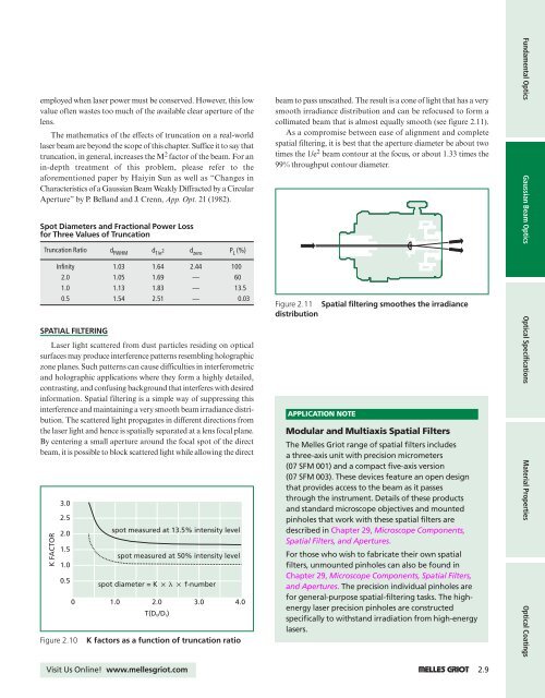
beam to pass unscathed. The result is a cone of light that has a very<br />
smooth irradiance distribution and can be refocused to form a<br />
collimated beam that is almost equally smooth (see figure 2.11).<br />
As a compromise between ease of alignment and complete<br />
spatial filtering, it is best that the aperture diameter be about two<br />
times the 1/e 2 beam contour at the focus, or about 1.33 times the<br />
99% throughput contour diameter.<br />
Figure 2.11 Spatial filtering smoothes the irradiance<br />
distribution<br />
APPLICATION NOTE<br />
Modular and Multiaxis Spatial Filters<br />
The Melles Griot range of spatial filters includes<br />
a three-axis unit with precision micrometers<br />
(07 SFM 001) and a compact five-axis version<br />
(07 SFM 003). These devices feature an open design<br />
that provides access to the beam as it passes<br />
through the instrument. Details of these products<br />
and standard microscope objectives and mounted<br />
pinholes that work with these spatial filters are<br />
described in Chapter 29, Microscope Components,<br />
Spatial Filters, and Apertures.<br />
For those who wish to fabricate their own spatial<br />
filters, unmounted pinholes can also be found in<br />
Chapter 29, Microscope Components, Spatial Filters,<br />
and Apertures. The precision individual pinholes are<br />
for general-purpose spatial-filtering tasks. The highenergy<br />
laser precision pinholes are constructed<br />
specifically to withstand irradiation from high-energy<br />
lasers.<br />
Fundamental Optics Gaussian Beam Optics <strong>Optical</strong> Specifications Material Properties <strong>Optical</strong> <strong>Coatings</strong><br />
Visit Us Online! www.mellesgriot.com 1 2.9


