Introduction to TopTurn CNC simulator turning Version 7.1
Introduction to TopTurn CNC simulator turning Version 7.1
Introduction to TopTurn CNC simulator turning Version 7.1

You also want an ePaper? Increase the reach of your titles
YUMPU automatically turns print PDFs into web optimized ePapers that Google loves.
Mathematisch Technische<br />
Software-Entwicklung GmbH<br />
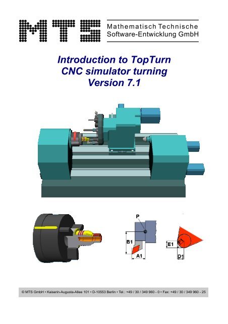
<strong>Introduction</strong> <strong>to</strong> <strong>TopTurn</strong><br />
<strong>CNC</strong> simula<strong>to</strong>r <strong>turning</strong><br />
<strong>Version</strong> <strong>7.1</strong><br />
© MTS GmbH • Kaiserin-Augusta-Allee 101 • D-10553 Berlin • Tel.: +49 / 30 / 349 960 - 0 • Fax: +49 / 30 / 349 960 - 25
MTS – <strong>Introduction</strong> <strong>to</strong> <strong>TopTurn</strong> <strong>Version</strong> <strong>7.1</strong><br />
<strong>Introduction</strong> <strong>to</strong> <strong>TopTurn</strong><br />
<strong>Version</strong> V<strong>7.1</strong><br />
© MTS Mathematisch Technische Software-Entwicklung GmbH<br />
Kaiserin-Augusta-Allee 101 • D - 10553 Berlin • Tel.: (030) 349 960 0 • Fax: 349 960 25<br />
Berlin, 2006.<br />
Any form of reproduction, including pho<strong>to</strong>-mechanical copies and copies in electronic form, requires our prior authorization.<br />
We are always grateful for improvement suggestions and reports on any errors detected<br />
Seite: 2 © MTS GmbH 2006
MTS – <strong>Introduction</strong> <strong>to</strong> <strong>TopTurn</strong> <strong>Version</strong> <strong>7.1</strong><br />
1.0. INTRODUCTION ...................................................................................................................................... 5<br />
1.1. HOW OPERATING ELEMENTS ARE REPRESENTED IN TOPTURN.................................................. 5<br />
1.2. STARTING OF TOPTURN....................................................................................................................... 6<br />
1.3. NOTES ON SETTING UP A CONFIGURATIONTYPE............................................................................ 7<br />
2.0. TOPTURN – THE <strong>CNC</strong> SIMULATOR TURNING .................................................................................... 8<br />
2.1. AUTOMATIC MODE ................................................................................................................................ 9<br />
2.2. INTERACTIVE MODE ............................................................................................................................ 10<br />
2.3. SINGLE BLOCK MODE......................................................................................................................... 11<br />
2.4. TOOL TRACING .................................................................................................................................... 12<br />
2.5. MEASURING AND INSPECTION.......................................................................................................... 13<br />
2.6. 3D REPRESENTATION AND SURFACE FINISH................................................................................. 14<br />
2.7. 2D REPRESENTATION......................................................................................................................... 15<br />
3.0. THE NC EDITOR.................................................................................................................................... 17<br />
3.1. SETUP SHEET....................................................................................................................................... 18<br />
3.2. KEYBOARD LAYOUT FOR NC EDITOR FUNCTIONS........................................................................ 19<br />
3.3. NC DIALOG PROGRAMMING .............................................................................................................. 20<br />
3.4. ADDITIONAL INFORMATION TO MTS NC EDITOR ........................................................................... 21<br />
4.0 THE “TURNING” SET-UP DIALOG........................................................................................................ 22<br />
4.1. OPEN THE DIALOG WINDOW AND ASSIGN A PROGRAM NAME .................................................... 22<br />
4.2. SELECT THE CLAMPING DEVICE AND CLAMPING CONFIGURATION.......................................... 22<br />
4.3. WERKSTÜCKMAßE UND NULLPUNKT DEFINIEREN ....................................................................... 23<br />
4.4. SELECT THE MACHINING TOOL SET ................................................................................................ 24<br />
4.5. PROGRAM FOR EXERCISES 01.DNC................................................................................................. 25<br />
5.0. SETUP MODE OVERVIEW.................................................................................................................... 26<br />
5.1. CLAMPING DEVICES, CLAMPING METHODS OF BLANK MATERIAL SHAPES............................ 26<br />
5.2. TOOL TURRETS, TOOL MOUNTINGS AND TOOLS........................................................................... 26<br />
5.3. TOOL LIBRARY..................................................................................................................................... 27<br />
5.4. AXIS MOTIONS IN SETUP MODE ........................................................................................................ 27<br />
6.0. PREPARATIONS FOR PROGRAMMING ............................................................................................. 28<br />
6.1. PRODUCTION PLANNING AND TECHNOLOGY ................................................................................ 29<br />
© MTS GmbH 2006 Seite: 3
MTS – <strong>Introduction</strong> <strong>to</strong> <strong>TopTurn</strong> <strong>Version</strong> <strong>7.1</strong><br />
6.2. SETUP FORM FOR “TURNING WORKPART 1” ................................................................................. 31<br />
6.3. PRODUCTION SHEET FOR „TURNING WORKPART 1” ................................................................... 32<br />
Sequence of machining steps........................................................................................................................ 32<br />
7.0. SETTING UP THE MACHINE ................................................................................................................ 33<br />
8.0. NC PROGRAMMING IN MTS PROGRAMMING KEY .......................................................................... 43<br />
8.1. INSIDE STRAIGHT ROUGHING CYCLE G81 ...................................................................................... 44<br />
8.2. DRILLING CYCLE G84.......................................................................................................................... 45<br />
8.3. OUTSIDE STRAIGHT ROUGHING CYCLE G81 .................................................................................. 46<br />
8.4. INSIDE STRAIGHT ROUGHING CYCLE G81 ...................................................................................... 46<br />
8.5. INSIDE FINISHING................................................................................................................................. 47<br />
8.6. OUTSIDE FINISHING............................................................................................................................. 47<br />
8.7. OUTSIDE THREAD-CUTTING CYCLE G31 ......................................................................................... 48<br />
8.8. OUTSIDE GROOVE-CUTTING CYCLE G79......................................................................................... 49<br />
8.9. INSIDE GROOVE-CUTTING.................................................................................................................. 50<br />
9.0. QUALITY CONTROL – MEASURING OF WORKPART....................................................................... 51<br />
10.0 APPENDICES ........................................................................................................................................ 52<br />
10.1. NC PROGRAM %3................................................................................................................................. 53<br />
10.2. WORKPART DRAWING ........................................................................................................................ 56<br />
10.3. WORKING TEMPLATES ....................................................................................................................... 57<br />
Tool data / magazine or turret positions ........................................................................................................ 57<br />
Sequence of machining steps........................................................................................................................ 58<br />
NC-Code ........................................................................................................................................................ 59<br />
10.4. NOTICE FOR ADMINISTRATING AND ORGANISING OF SETUP TURNING ................................... 60<br />
10.5. SYSTEM INFORMATION....................................................................................................................... 62<br />
Seite: 4 © MTS GmbH 2006
MTS – <strong>Introduction</strong> <strong>to</strong> <strong>TopTurn</strong> <strong>Version</strong> <strong>7.1</strong><br />
1.0. <strong>Introduction</strong><br />
The individual chapters of this manual explain the essential functions involved in operating and handling the<br />
system. The functions described here are also intended <strong>to</strong> give you a general idea of the system’s capabilities<br />
(as well as the possibilities offered for implementing dedicated training courses).<br />
These not only include the creation of NC programs and simulating and checking their quality, but also many<br />
other realistic ways of teaching the trainees basic <strong>CNC</strong> machine <strong>to</strong>ol functions using computer support.<br />
The examples used in the simulation are available in the programming keys of all <strong>CNC</strong> control systems supplied<br />
by our company.<br />
Trainees are guided through system operation step-by-step, enabling them <strong>to</strong> learn the underlying principles<br />
and the operation of the <strong>CNC</strong> simula<strong>to</strong>r in a very short time.<br />
After some introduc<strong>to</strong>ry explanations, we will first show you how <strong>to</strong> set up the simula<strong>to</strong>r according <strong>to</strong> a work plan<br />
and how <strong>to</strong> create a setup sheet.<br />
1.1. How operating elements are represented in <strong>TopTurn</strong><br />
The operating elements and the meaning of their functions are shown by the simula<strong>to</strong>r as 10 function but<strong>to</strong>ns in<br />
a menu bar at the bot<strong>to</strong>m of the screen corresponding <strong>to</strong> the function keys of a PC or control keyboard.<br />
Main menu:<br />
To activate the desired function, either move the mouse pointer <strong>to</strong> the respective function but<strong>to</strong>n and click on<br />
the leftt-hand mouse but<strong>to</strong>n , or press the appropriate function key … of the PC keyboard. This<br />
enables you <strong>to</strong> adapt system operation <strong>to</strong> your preferences.<br />
To help you follow the explanations more easily, the functions which you have <strong>to</strong> select from the menu<br />
structures are shown in the explana<strong>to</strong>ry and instruction texts with a coloured or darker background, or are<br />
indicated by symbols representing PC keys.<br />
To begin with, you only need <strong>to</strong> carry out the individual steps as instructed.<br />
If the desired result is not achieved due <strong>to</strong> an input error, please observe the following notes:<br />
• You can return <strong>to</strong> the main menu or the start-up status of the simula<strong>to</strong>r at any time by pressing the or<br />
key. Depending on how far down the menu tree you are, you may have <strong>to</strong> press the key several times.<br />
• To select or de-select functions, use the keys … . This may pull up a new menu.<br />
• Generally, a function is concluded or accepted by pressing . If you have navigated through several<br />
menus in order <strong>to</strong> select a specific function, you will have <strong>to</strong> exit each menu, one at a time by pressing<br />
or the appropriate number of times. This, <strong>to</strong>o, will return you <strong>to</strong> the main menu.<br />
Instead of using the function keys the windows <strong>to</strong>olbar can be used for operation<br />
© MTS GmbH 2006 Seite: 5
MTS – <strong>Introduction</strong> <strong>to</strong> <strong>TopTurn</strong> <strong>Version</strong> <strong>7.1</strong><br />
1.2. Starting of <strong>TopTurn</strong><br />
Click on the Windows START but<strong>to</strong>n in the task bar, select the Programs folder and then (sofar you have not<br />
changed the folder name when installing the software) the MTS-<strong>CNC</strong> English folder <strong>to</strong> access the MTS<br />
programs <strong>TopTurn</strong>, TopMill or TopCAM.<br />
The respective documentation / training manuals are s<strong>to</strong>red in PDF format in the Help subfolder.<br />
If you start TOPCAM, the start-up menu will offer you the following software modules for selection:<br />
TopCAM<br />
A CAD system with integrated NC programming for<br />
<strong>turning</strong>/lathe work with up <strong>to</strong> 5 axes and milling work<br />
with 3 axes<br />
<strong>TopTurn</strong><br />
NC programming module, either control-systemspecific<br />
or of neutral ISO control system type, with<br />
simulation and collision detection; optionally available<br />
with opposite spindle and up <strong>to</strong> 7 axes<br />
TopMill<br />
NC programming module, either control-systemspecific<br />
or of neutral ISO control system type, with<br />
simulation and collision detection in 3 axes<br />
When you start up the TURNING software for the first time, an MTS configuration group with the MTS<br />
programming key will always be active::<br />
MTS TM -___.___.042x0500x1000 x MTS TM CONTROL<br />
If you have not purchased the MTS programming key, which is independent of the type of control system, but<br />
have a <strong>turning</strong>/lathe work control system using e. g. PAL94 command codes or SINUMERIK 820T, the Start<br />
Turning but<strong>to</strong>n is not active after you have installed the software. In this case, you first have <strong>to</strong> select a<br />
corresponding configuration group. This activates the Start Turning but<strong>to</strong>n. This configuration group selection<br />
is memorized for subsequent program starts.<br />
Click left hand mouse but<strong>to</strong>n <strong>to</strong> select<br />
a configuration group<br />
Info on the machine <strong>to</strong>ol axes, tails<strong>to</strong>ck<br />
in the selected configuration<br />
Seite: 6 © MTS GmbH 2006
MTS – <strong>Introduction</strong> <strong>to</strong> <strong>TopTurn</strong> <strong>Version</strong> <strong>7.1</strong><br />
1.3. Notes on setting up a configurationtype<br />
You can skip over this chapter when first learning <strong>to</strong> operate the software.<br />
The name of a configuration group is always related <strong>to</strong> a particular combination of machine <strong>to</strong>ol and control<br />
system configurations. These are saved and managed by the Configuration Administration. For instance, a lathe<br />
will be configured according <strong>to</strong> the manufacturer’s instructions. The definitive properties will include the<br />
machining space, <strong>to</strong>ol travel ranges, <strong>to</strong>ol magazine type and the <strong>to</strong>ol positions, number of NC axes, whether a<br />
opposite spindle, heads<strong>to</strong>ck or tails<strong>to</strong>ck are installed etc.<br />
The control configuration will comprise the <strong>CNC</strong> programming syntax, the allocation of the optional<br />
postprocessor and the control settings.<br />
A postprocessor is always needed for translating an MTS<br />
or PAL program in<strong>to</strong> a specific control system code. The<br />
same as with the programming key, this will be activated<br />
after the target control system has been selected.<br />
Which of these modules are available will depend on which software level you have purchased. You can add<br />
modules whenever required.<br />
In the following illustration, both modules, i. e. the programming key and the postprocessor are available. The<br />
Postprocessor and Start <strong>turning</strong> but<strong>to</strong>ns are therefore enabled and activated.<br />
Driving <strong>to</strong>ol 5 axes machining (X, Z, Y, B, C) main<br />
spindle and Counterspindel<br />
Programming key of the control Sinumerik 810D<br />
with 5 axes simulation<br />
Cycle postprocessor for translating programs in<strong>to</strong><br />
the Sinumerik 810 D NC code for 5 axes<br />
Transfer of the NC data between the PC AND THE nc<br />
machine <strong>to</strong>ol<br />
If you have not purchased a programming key for your postprocessor, then the<br />
enabled.<br />
but<strong>to</strong>n is not<br />
Before continuing, re-check the active configuration group.<br />
Now start the <strong>CNC</strong> simula<strong>to</strong>r by double-clicking on the but<strong>to</strong>n. The simula<strong>to</strong>r will either use the<br />
MTS TM -___.___.042x0500x1000 x MTS TM CONTROL<br />
configuration group as in the example bevor, or the one which you have purchased.<br />
© MTS GmbH 2006 Seite: 7
MTS – <strong>Introduction</strong> <strong>to</strong> <strong>TopTurn</strong> <strong>Version</strong> <strong>7.1</strong><br />
2.0. <strong>TopTurn</strong> – the <strong>CNC</strong> simula<strong>to</strong>r <strong>turning</strong><br />
The <strong>CNC</strong> simula<strong>to</strong>r has three different operating modes:<br />
NC Edi<strong>to</strong>r<br />
Au<strong>to</strong>matic mode<br />
Setup mode<br />
Setup dialog<br />
For teaching purposes, it is best <strong>to</strong> start with the <br />
get familiar with the various types of simulation.<br />
. This means that the trainee will first<br />
We switch the simula<strong>to</strong>r <strong>to</strong> 3D<br />
Let us start by explaining some features of the initial screen display.<br />
The power-on state of the <strong>CNC</strong> simula<strong>to</strong>r is<br />
determined by a setup sheet. This describes a specific<br />
simula<strong>to</strong>r setup which is determined by the following<br />
components:<br />
• a lathe chuck with clamping jaws,<br />
• the workpiece blank / blank material and<br />
• <strong>to</strong>oling setup with <strong>to</strong>ol positions in the <strong>to</strong>ol<br />
magazine.<br />
The start setup sheet is s<strong>to</strong>red as header in an NC<br />
program. In each control system, it is s<strong>to</strong>red under the<br />
program administration and is named<br />
. The user can adapt this setup<br />
sheet individually or can change its name of in the<br />
respective control system configuration.<br />
To activate the program and set up<br />
the system, select by mouse pointer<br />
or press the key. This returns the simula<strong>to</strong>r <strong>to</strong> its<br />
original power-on state.<br />
Header of the setup sheet as are<br />
shown by the NC edi<strong>to</strong>r.<br />
For further information on setup sheets, refer <strong>to</strong> Chapter 3.1,<br />
Seite: 8 © MTS GmbH 2006
MTS – <strong>Introduction</strong> <strong>to</strong> <strong>TopTurn</strong> <strong>Version</strong> <strong>7.1</strong><br />
2.1. Au<strong>to</strong>matic mode<br />
We want <strong>to</strong> run an NC program on a <strong>CNC</strong> machine <strong>to</strong>ol. To enable this process, the program first has <strong>to</strong> be<br />
loaded in<strong>to</strong> the control system’s memory. The following description illustrates the individual steps required <strong>to</strong><br />
operate the MTS system in this mode.<br />
Press key , or select the but<strong>to</strong>n <strong>to</strong> open the NC Program Administration, which will<br />
display a list of all NC programs for this control system<br />
Double-click on the file name <strong>to</strong> load<br />
this NC Program in<strong>to</strong> the machine <strong>to</strong>ol memory for further processing.<br />
With mouse click you can activate further functions of the explorer:<br />
e.g. copy program <strong>to</strong> diskette,<br />
delete, rename etc..<br />
In our example, the program has been selected. Press <strong>to</strong> confirm the<br />
action. The system will display a new menu. This offers you four different types of simulation. We shall start<br />
byselecting au<strong>to</strong>matic mode .<br />
Au<strong>to</strong>matic mode<br />
Interactive mode<br />
Single block<br />
Tool tracing<br />
To start the simulation in au<strong>to</strong>matic mode, press the key. The <strong>CNC</strong> program currently loaded in<strong>to</strong> the<br />
machine memory is run au<strong>to</strong>matically from the first <strong>to</strong> the last block.<br />
The right-hand pane shows important system<br />
information on the operating state of the virtual <strong>CNC</strong><br />
lathe:<br />
• current co-ordinates of the X and Z axis (as well<br />
as of the optional additional axes),<br />
• cutting speed, rotation speed, <strong>to</strong>ol feed,<br />
<strong>to</strong>ol number,<br />
• direction of spindle rotation, machining time,<br />
• active G code and<br />
• override & runtime<br />
The lower section of the simulation window shows a<br />
section of the program with the NC block currently<br />
being processed by <strong>TopTurn</strong><br />
© MTS GmbH 2006 Seite: 9
MTS – <strong>Introduction</strong> <strong>to</strong> <strong>TopTurn</strong> <strong>Version</strong> <strong>7.1</strong><br />
2.2. Interactive mode<br />
Interactive mode, called up by pressing the key, enables the user <strong>to</strong> write, <strong>to</strong>create, edit and run an NC<br />
program in dialog with the software. The <strong>CNC</strong> simula<strong>to</strong>r runs the NC program block-by-block. The program can<br />
be corrected at any time. After being executed by the simula<strong>to</strong>r, any block can be rejected so that you can reedit<br />
it and then re-run on the simula<strong>to</strong>r. During this process, the workpiece will be continuously updated, or, if<br />
the block is rejected, the workpiece will be returned <strong>to</strong> its former condition.<br />
Let us run the NC program in .<br />
Initially, the program administration is opened:<br />
Double-click left on the programm in<br />
order <strong>to</strong> transfer it <strong>to</strong> the machine program memory.<br />
This will get the program wunning in interactive mode. After editing and confirmation every NC block will be<br />
simulated and this block will be represented for editing after simulation.<br />
Execute an NC block:<br />
Accept NC block [Y/N]<br />
Execute an NC block<br />
Accept NC block [Y/N]<br />
In this operating mode, the NC code can be edited<br />
again as follows:<br />
Reject the block by pressing the or . Using<br />
the keyboard, edit the current block.<br />
Accept NC block [Y/N]<br />
Instead of you may press also .<br />
Seite: 10 © MTS GmbH 2006
MTS – <strong>Introduction</strong> <strong>to</strong> <strong>TopTurn</strong> <strong>Version</strong> <strong>7.1</strong><br />
If you wish <strong>to</strong> change the speed at which the simulation is run, use the function . This<br />
function is available on all modern machine <strong>to</strong>ols, both during machining work and during <strong>to</strong>oling and set-up<br />
(zero-position scratching, setting zero co-ordinates).<br />
To access the various functions for altering the time taken <strong>to</strong> run the simulation, press the but<strong>to</strong>n. Try using the individual options offered in the menu bar. To apply your settings, press key .<br />
You may change the settings at any time.<br />
Important: The override setting affects the calculated machining time. As opposed <strong>to</strong> this, the slow-motion and<br />
test run on/off functions do not affect calculated machining times.<br />
2.3. Single block mode<br />
The function is used when running in Au<strong>to</strong>matic mode and requires the opera<strong>to</strong>r <strong>to</strong> confirm the<br />
execution of each NC block or record individually.<br />
The NC-Program should be executed in the operating mode <br />
.<br />
Click on or press the<br />
with <strong>to</strong> run the NC block.<br />
or confirm<br />
Note:<br />
You can switch over between the simulation modes Au<strong>to</strong>matic mode, Single block and Interactive mode<br />
even after simulation of an NC program has been started.<br />
© MTS GmbH 2006 Seite: 11
MTS – <strong>Introduction</strong> <strong>to</strong> <strong>TopTurn</strong> <strong>Version</strong> <strong>7.1</strong><br />
2.4. Tool tracing<br />
The function is used <strong>to</strong> display the <strong>to</strong>ol travel paths described by the selected NC program e. g.<br />
.<br />
The program is run and the programmed 3D <strong>to</strong>ol tracing of the the <strong>to</strong>ol tip are displayed graphically and each<br />
<strong>to</strong>ol is shown in different colors.<br />
Careful and precise evaluation of the programmed <strong>to</strong>ol movements in rapid speed and subsequent correction of<br />
the NC program can lead <strong>to</strong> considerable reductions in manufacturing times.<br />
With the <strong>to</strong>olbar you can manipulate the graphic display of the <strong>to</strong>ol tracing and you can also alternatively insert<br />
the workpart.<br />
Note:<br />
The currently selected NC program can be run in any of the simulation modes.<br />
<br />
<br />
<br />
<br />
If the setup sheet interpreter is activated, every time an NC program is started the <strong>CNC</strong> simula<strong>to</strong>r will be set up<br />
according <strong>to</strong> the setup sheet in the header of the NC program. This has the advantage that the original<br />
workpiece blank is always placed back on the machine whenever the program is restarted.<br />
Seite: 12 © MTS GmbH 2006
MTS – <strong>Introduction</strong> <strong>to</strong> <strong>TopTurn</strong> <strong>Version</strong> <strong>7.1</strong><br />
2.5. Measuring and inspection<br />
Irrespective of the simulation mode you have selected and the NC code already processed, you can use the<br />
but<strong>to</strong>n at any time <strong>to</strong> call up functions for displaying and checking the workpiece in its actual<br />
state.<br />
The but<strong>to</strong>n gives you access <strong>to</strong> simula<strong>to</strong>r functions relevant <strong>to</strong> the <strong>to</strong>pic of quality analysis<br />
and checking of your own work.<br />
The trainee is offered a comprehensive range of functions for checking the results of the work he/she has done.<br />
The function , or is used <strong>to</strong> make a “specifications/as is”<br />
comparison in order <strong>to</strong> check whether the programmed workpiece con<strong>to</strong>ur really matches the drawing<br />
specifications.<br />
Now try using the various functions offered, e. g. <strong>to</strong> examine the effect of the cutting <strong>to</strong>ol radius compensation<br />
on the workpiece con<strong>to</strong>urs by measuring the workpiece alternately with compensation on and off.<br />
Exit with .<br />
© MTS GmbH 2006 Seite: 13
MTS – <strong>Introduction</strong> <strong>to</strong> <strong>TopTurn</strong> <strong>Version</strong> <strong>7.1</strong><br />
2.6. 3D representation and surface finish<br />
The viewing angle, viewer distance and zoom fac<strong>to</strong>r,<br />
as well as a cut-away section angle, can be set <strong>to</strong> suit<br />
your requirements. In the sections menu, you can<br />
define the cut-away segment..<br />
To obtain a full-screen display, press + , you<br />
can only switch back <strong>to</strong> the normal user interface by<br />
pressing the key. With the <strong>to</strong>olbar you can also<br />
obtain a permanent 3D representation of the selected<br />
<strong>to</strong>ol<br />
Roughness depth analyse<br />
, calls up a function <strong>to</strong> analyse the workpiece<br />
con<strong>to</strong>ur by individual con<strong>to</strong>ur entities, one at a time.<br />
Using the cutting <strong>to</strong>ol geometry and feed, the system<br />
will calculate and display the surface and determine<br />
the roughness depth average value. To obtain more<br />
detailed information on the currently selected con<strong>to</strong>ur<br />
entity, press keys and .<br />
Seite: 14 © MTS GmbH 2006
MTS – <strong>Introduction</strong> <strong>to</strong> <strong>TopTurn</strong> <strong>Version</strong> <strong>7.1</strong><br />
2.7. 2D representation<br />
The functions accessed by the or<br />
three ways:<br />
key allow you <strong>to</strong> modify the on-screen display mode in<br />
• Workpiece views<br />
• Zoom functions<br />
• NC code line display<br />
To apply the setting changes made in the , press the key; <strong>to</strong> reject them, press .<br />
A rectangular zoom section will be defined by the two<br />
points of a section diagonal.To define a zoom section,<br />
click with the left-hand mouse but<strong>to</strong>n on one edge<br />
of the rectangle and drag the mouse pointer <strong>to</strong> the<br />
diagonally opposite corner of the rectangle..<br />
You can always switch back instantly <strong>to</strong> the overall<br />
view of the machining space or <strong>to</strong> a standard display<br />
related <strong>to</strong> the workpiece blank.<br />
After selecting the new display mode, exit the menu by clicking on the but<strong>to</strong>n or by pressing . The<br />
selected view mode will remain in force until it is changed again. (Except when the NC program itself calls up a<br />
window setting). The simula<strong>to</strong>r will return <strong>to</strong> the function which was selected at the time you called up the<br />
functions.<br />
© MTS GmbH 2006 Seite: 15
MTS – <strong>Introduction</strong> <strong>to</strong> <strong>TopTurn</strong> <strong>Version</strong> <strong>7.1</strong><br />
The following workpiece geometry views can be selected: outside view, half-section (<strong>to</strong>p or bot<strong>to</strong>m half) and full<br />
longitudinal section.<br />
Outside view display<br />
Display showing bot<strong>to</strong>m half-section<br />
Display showing full section<br />
The but<strong>to</strong>n or key calls up a<br />
function which you can use <strong>to</strong> define the number of<br />
lines of NC code <strong>to</strong> be displayed in au<strong>to</strong>matic mode.<br />
Seite: 16 © MTS GmbH 2006
MTS – <strong>Introduction</strong> <strong>to</strong> <strong>TopTurn</strong> <strong>Version</strong> <strong>7.1</strong><br />
3.0. The NC Edi<strong>to</strong>r<br />
The initial menu of the NC edi<strong>to</strong>r provides access <strong>to</strong> the following functions:<br />
• Edit the current NC program<br />
• not assigned<br />
• Select an NC program from the Administration in order <strong>to</strong> edit it, or <strong>to</strong> create a new program<br />
• not assigned<br />
• Print the NC program<br />
• Transfer the NC program <strong>to</strong> the machine <strong>to</strong>ol in DNC mode<br />
• Return <strong>to</strong> setup mode<br />
• Return <strong>to</strong> au<strong>to</strong>matic mode<br />
•<br />
As you already learned in the section on , you can select a program or create a new<br />
program using the file selection dialog.<br />
This offers various ways of opening or creating a program. Press or click on , and enter<br />
a program name.<br />
If a program with this name already exists, it will be opened for editing, if not, you will be shown a message:<br />
“Program does not exist! Create program [Y/N]?”. In the latter case, press the [Y] key <strong>to</strong> create a new<br />
program and [N] [<strong>to</strong> abort.<br />
You can also select a program by clicking or pressing . The selected name is then<br />
copied in<strong>to</strong> the simula<strong>to</strong>r’s status bar when the dialog window is closed. You can subsequently open it with<br />
or by using other functions.<br />
The NC program is <strong>to</strong> be opened for viewing. It contains all<br />
required information, from the setup data for simulation<br />
right down <strong>to</strong> the NC code of the program.<br />
After you have marked the NC program with a single<br />
left mouse click , you can click on the right-hand<br />
mouse but<strong>to</strong>n <strong>to</strong> call up further supplementary<br />
functions.<br />
© MTS GmbH 2006 Seite: 17
MTS – <strong>Introduction</strong> <strong>to</strong> <strong>TopTurn</strong> <strong>Version</strong> <strong>7.1</strong><br />
3.1. Setup sheet<br />
A setup sheet s<strong>to</strong>red as header of an NC program always has the same structure. It comprises the following<br />
groups:<br />
• Machine <strong>to</strong>ol and control system configuration names,<br />
• Workpiece blank and geometry<br />
• Clamping devices and their positioning<br />
• Active <strong>to</strong>ol in the machining position<br />
• Tools in the <strong>to</strong>ol magazine, <strong>to</strong>ol positions including <strong>to</strong>ol correction values<br />
In the main menu, click on or press<br />
in order <strong>to</strong> access the setup form menu.<br />
After the simula<strong>to</strong>r was set-up in setup mode you can save this setup in a respective setup sheet:<br />
Press and enter a program name.<br />
Setup sheet information<br />
• () Beginning and end marks for the setup sheet interpreter<br />
• ( Setup sheet line which is <strong>to</strong> be processed by the interpreter<br />
• (( Comments, these are not <strong>to</strong> be processed by the interpreter<br />
When you create a new setup sheet, the command (meaning “end of program”) will be the only NC line<br />
<strong>to</strong> be added <strong>to</strong> the setup sheet. Without the error message “unanticipated end of program” will be<br />
displayed when you are working in au<strong>to</strong>matic mode or when the setup sheet is being used as a startup setup<br />
sheet.<br />
Seite: 18 © MTS GmbH 2006
MTS – <strong>Introduction</strong> <strong>to</strong> <strong>TopTurn</strong> <strong>Version</strong> <strong>7.1</strong><br />
3.2. Keyboard layout for NC edi<strong>to</strong>r functions<br />
The section of the program that can currently be edited is always shown between two horizontal rules. To select<br />
a word, use the cursor key . You can change, delete or write new code as you wish.<br />
Confirm and conclude your entries by pressing the<br />
key.<br />
Browse a page at a time<br />
Browse block by block<br />
or<br />
or<br />
Insert a line: +<br />
Delete a line: +<br />
Inset a word:<br />
Delete a word:<br />
• Link programs<br />
• Group operation<br />
• Renumber the NC program<br />
To insert another NC program in front of the currently selected line, call up the appropriate function by pressing<br />
the key or clicking on on . This is an important function that is needed for creating<br />
modification copies, for instance.<br />
The group operation function, called up by pressing the key, enables you <strong>to</strong> mark a block of multiple<br />
complete lines, including the beginning and end marks, and then carry out operations such as shift, copy or<br />
delete block.<br />
The Renumber functions called up by pressing enable you <strong>to</strong> renumber the NC program from a first<br />
program number up <strong>to</strong> another program number by specifying a start number and a numbering increment.<br />
© MTS GmbH 2006 Seite: 19
MTS – <strong>Introduction</strong> <strong>to</strong> <strong>TopTurn</strong> <strong>Version</strong> <strong>7.1</strong><br />
3.3. NC dialog programming<br />
To enter dialog programming mode, press the key or click on . This is a universal MTS<br />
software function which can be adapted <strong>to</strong> all types of NC controls. When you press the key, the current<br />
work line is analyzed <strong>to</strong> locate commands for which a dialog screen is available. If a fitting dialog screen is<br />
found, it will be displayed and the respective input parameter values shown in the dialog screen.<br />
Dialog screen<br />
List of contentc<br />
In the above example, this is an MTS straight roughing machining cycle call G81 with three addresses: X, Z and<br />
I, as well as supplementary parameters which have not yet been assigned values in the example. You can<br />
change the address values and also add values from the dialog screen. To enter all values in<strong>to</strong> the actual NC<br />
program, click on the but<strong>to</strong>n.<br />
If no key word is found, the dialog programming module will call up the list of contents showing all available<br />
commands, allowing you <strong>to</strong> select one of these by clicking on “Parameter” . The corresponding dialog<br />
screen is then opened so that you can enter the desired values. Click on <strong>to</strong> confirm your input. The<br />
corresponding new NC code line will replace the line originally selected. If you have accessed the end of the NC<br />
program, a new line will be appended <strong>to</strong> the existing NC program. (This operation also applies <strong>to</strong> multiple-line<br />
NC programming commands, provided that the selected NC control system supports these).<br />
You can either enter a numerical value, or in the case of switch functions, select the respective function setting.<br />
In this procedure, the permissible value ranges are checked and a distinction is made between manda<strong>to</strong>ry<br />
addresses and optional addresses. You also have the option of using an alternative address combination, e. g.<br />
defining an arc by I and K instead of by the radius.<br />
In dialog programming of more complex cycles, you<br />
can also call up the corresponding Windows help<br />
screens if available for this specific control..<br />
Seite: 20 © MTS GmbH 2006
MTS – <strong>Introduction</strong> <strong>to</strong> <strong>TopTurn</strong> <strong>Version</strong> <strong>7.1</strong><br />
3.4. Additional information <strong>to</strong> MTS NC edi<strong>to</strong>r<br />
The function key Dialog/Help can also be activated by pressing the key combination + , or by clicking<br />
on with the right mouse but<strong>to</strong>n , <strong>to</strong> get in<strong>to</strong> a help box for <strong>to</strong>ol magazine informations.<br />
Enter T in the input field and confirm with<br />
magazine equipment of the <strong>CNC</strong> simula<strong>to</strong>r.<br />
, then you will get the information display of the actual <strong>to</strong>ol<br />
Here you can get additional informations about the<br />
marked <strong>to</strong>ol.<br />
Note:<br />
The modification of the <strong>to</strong>ol equipment is not possible<br />
in this helpscreen.<br />
Press<br />
<strong>to</strong> leave this <strong>to</strong>ol magazine information.<br />
© MTS GmbH 2006 Seite: 21
MTS – <strong>Introduction</strong> <strong>to</strong> <strong>TopTurn</strong> <strong>Version</strong> <strong>7.1</strong><br />
4.0 The “<strong>turning</strong>” set-up dialog<br />
Four simple steps <strong>to</strong> create a setup sheet<br />
The set-up dialog assists you <strong>to</strong> create a setup sheet for a new programming task quickly. First, the clamping<br />
device - e.g a chuck and jaws - is selected. Then the workpiece - a cylinder or a pipe - is defined, the workpiece<br />
origin is specified and the new program is completed by adding a suitable set of <strong>to</strong>ols. After the procedure is<br />
finished, the controls read in the setup sheet in the form of a program header, and the user can immediately<br />
start <strong>to</strong> key in the new program.<br />
4.1. Open the dialog window and assign a program name<br />
To open the set-up dialog, press key . Enter a<br />
new name for the <strong>CNC</strong> program you wish <strong>to</strong> create,<br />
e. g. "Exercise 01" and then open the program<br />
4.2. Select the clamping device and clamping configuration<br />
Select the clamping device.<br />
Explanation:<br />
7 different clamping devices are offered for selection. A clamping depth definition is not necessary in case of<br />
peak clamping. In this case the workpart must have a centering. Is the workpart a pipe, an external and internal<br />
diameter must be entered.<br />
Seite: 22 © MTS GmbH 2006
MTS – <strong>Introduction</strong> <strong>to</strong> <strong>TopTurn</strong> <strong>Version</strong> <strong>7.1</strong><br />
Select the clamping device<br />
KFD-HS 130 min.46 max.118 Et=18<br />
Determine the clamping depth of the workpart<br />
Input: 18 mm<br />
Next open the tab:<br />
Blank/Zero point<br />
Explanation:<br />
Observe the range of values in the display field. If a value cannot be evaluated, then it is shown in red in the<br />
input field and is not processed.<br />
Selection of the vise corresponds <strong>to</strong> the standard in the „Turning“ clamping device library.<br />
KFD-HS 130 min.46 max.118 Et=18<br />
KFD-HS 130 describes the lathe chuck, min. 46 til max. 118 mm describes the opening range of the respective<br />
jaw and Et=18 mm is the maximum clamping depth possible for a workpart.<br />
4.3. Werkstückmaße und Nullpunkt definieren<br />
Specify the workpart dimensions:<br />
Input length = 120 mm,<br />
Input width = 60 mm<br />
and enter a zero point shift from front side in<strong>to</strong> the<br />
material.<br />
Input<br />
Z= -2 mm<br />
Next open the tab:<br />
Tools<br />
Explanation:<br />
The position of the workpiece origin can be specified by selecting a value in the center input field of this tab.<br />
A <strong>to</strong>tal of 2 possible workpart origins are offered for selection: right or left from the workpart.<br />
Additionally this point can be moved incrementally in Z ± direction from the selected point.<br />
© MTS GmbH 2006 Seite: 23
MTS – <strong>Introduction</strong> <strong>to</strong> <strong>TopTurn</strong> <strong>Version</strong> <strong>7.1</strong><br />
4.4. Select the machining <strong>to</strong>ol set<br />
Select the <strong>to</strong>ol set e.g. 94-03 and inform about the<br />
<strong>to</strong>oling of the turret magazine.<br />
Next open the tab:<br />
Compensation value<br />
Explanation:<br />
The <strong>to</strong>ol set determines which <strong>to</strong>ols are <strong>to</strong> be made available on the setup sheet.<br />
You find here a list of compensation values.<br />
Explanation:<br />
Select the compensation values tab in order <strong>to</strong> obtain<br />
more detailed <strong>to</strong>ol information.<br />
Confirm your input by clicking on the but<strong>to</strong>n <strong>to</strong><br />
create the new setup sheet. This is then read in by the<br />
<strong>CNC</strong> machine <strong>to</strong>ol in Au<strong>to</strong>matic mode – Interactive<br />
programming – and you can then start programming<br />
the machine.<br />
The <strong>CNC</strong> program can be created immediately.<br />
The machine origin (zero point) specified in the dilaog<br />
is entered at the bot<strong>to</strong>m of the setup sheet and can<br />
then be activated with the assigned command, e.g.<br />
G54.<br />
Below is an excerpt from the setup sheet:<br />
(<br />
( WORKPART ZERO-POINT<br />
( G54 X200.000 Y+150.000 Z+105.000<br />
Seite: 24 © MTS GmbH 2006
MTS – <strong>Introduction</strong> <strong>to</strong> <strong>TopTurn</strong> <strong>Version</strong> <strong>7.1</strong><br />
4.5. Program for exercises 01.dnc<br />
()<br />
(( 06.04.2006 16:57<br />
(<br />
( CONFIGURATION<br />
( MACHINE MTS01 TM-016_-R1_-060x0646x0920<br />
( CONTROL MTS TM01<br />
(<br />
( PART<br />
( CYLINDER D+060.000 L+120.000<br />
(<br />
( MAIN SPINDLE WITH WORKPART<br />
( CHUCK KFD-HS 130<br />
( STEP JAW HM-110_130-02.001<br />
( TYPE OF CHUCK EXTERNAL CHUCK OUTSIDE STEP JAW<br />
( CHUCKING DEPTH E18.000<br />
(( Right side of the part: Z+230.000<br />
(<br />
( TOOLS<br />
( T01 "DIN69880 V 30\Left corner <strong>to</strong>ol\CL-SCLCL-2020 L 1208 ISO30"<br />
( T02 "DIN69880 V 30\Left corner <strong>to</strong>ol\CL-SVACL-2020 L 1604 ISO30"<br />
( T03 "DIN69880 V 30\Left corner <strong>to</strong>ol\CL-MTJNL-2020 L 1608 ISO30"<br />
( T04 "DIN69880 V 30\Round horizontal\CT-SRDCN-2016 L 0603 ISO30"<br />
( T05 "DIN69880 V 30\Left corner <strong>to</strong>ol\CL-SDJCL-2020 L 1208 ISO30"<br />
( T06 "DIN69880 V 30\Recessing <strong>to</strong>ol\EA-SGTFL-2012 L 02.5-0 ISO30"<br />
( T07 "DIN69880 V 30\Left threading <strong>to</strong>ol\TL-LHTR-2020 R 60 1.50 ISO30"<br />
( T08 "DIN69880 V 30\Left threading <strong>to</strong>ol\TL-LHTR-2020 R 60 2.00 ISO30"<br />
( T09 "DIN69880 V 30\Left corner <strong>to</strong>ol\CL-SVJCL-2020 L 1604 ISO30"<br />
( T10 "DIN69880 V 30\Twist drill\DR-18.00 130 R HSS ISO30"<br />
( T11 EMPTY<br />
( T12 EMPTY<br />
( T13 "DIN69880 V 30\Left threading <strong>to</strong>ol\TL-LHTR-2020 R 60 1.50 ISO30"<br />
( T14 "DIN69880 V 30\Recessing <strong>to</strong>ol\ER-SGTFL-1212 L 01.6-0 ISO30"<br />
(<br />
( TOOL COMPENSATION<br />
( D01 T01 Q3 R0.800 X+070.0 Z+045.000 G000.000 E005.005 I-0.800 K-000.800 A+004.375 L011.855 N01<br />
( D02 T02 Q3 R0.400 X+070.0 Z+045.000 G000.000 E052.393 I-0.400 K-000.400 A+002.372 L016.178 N01<br />
( D03 T03 Q3 R0.800 X+070.0 Z+045.000 G000.000 E02<strong>7.1</strong>30 I-0.800 K-000.800 A+002.372 L015.678 N01<br />
( D04 T04 Q8 R3.000 X+070.0 Z+034.000 G006.000 E090.000 I-3.000 K+000.000 A+000.000 L003.000 N01<br />
( D05 T05 Q3 R0.800 X+070.0 Z+045.000 G000.000 E032.178 I-0.800 K-000.800 A+002.372 L010.785 N01<br />
( D06 T06 Q3 R0.160 X+060.0 Z+041.250 G002.500 E000.000 I-0.160 K-000.160 A+000.000 L012.000 N01<br />
( D07 T07 Q8 R0.217 X+070.0 Z+042.699 G000.000 E000.000 I-0.217 K+000.000 A+000.000 L000.000 N01<br />
( D08 T08 Q8 R0.288 X+070.0 Z+042.699 G000.000 E000.000 I-0.288 K+000.000 A+000.000 L000.000 N01<br />
( D09 T09 Q3 R0.400 X+070.0 Z+045.000 G000.000 E052.393 I-0.400 K-000.400 A+002.372 L016.178 N01<br />
( D10 T10 Q7 R0.000 X+000.0 Z+204.000 G018.000 E059.000 I+0.000 K+000.000 A+000.000 L000.000 N01<br />
( D11 T11 Q0 R0.000 X+000.0 Z+000.000 G000.000 E000.000 I+0.000 K+000.000 A+000.000 L000.000 N01<br />
( D12 T12 Q0 R0.000 X+000.0 Z+000.000 G000.000 E000.000 I+0.000 K+000.000 A+000.000 L000.000 N01<br />
( D13 T13 Q8 R0.217 X+070.0 Z+042.699 G000.000 E000.000 I-0.217 K+000.000 A+000.000 L000.000 N01<br />
( D14 T14 Q3 R0.160 X+060.0 Z+041.300 G001.600 E000.000 I-0.160 K-000.160 A+000.000 L008.000 N01<br />
(<br />
( WORKPART ZEROPOINTS<br />
(( Right side of the part: Z+230.000<br />
( G54 X000.000 Z+228.000<br />
(<br />
()<br />
N0010 G54<br />
© MTS GmbH 2006 Seite: 25
MTS – <strong>Introduction</strong> <strong>to</strong> <strong>TopTurn</strong> <strong>Version</strong> <strong>7.1</strong><br />
5.0. Setup mode overview<br />
The setup mode integrated in<strong>to</strong> the <strong>TopTurn</strong> has a very wide function range. The following chapters provide a<br />
brief synopsis of the various options offered.<br />
5.1. Clamping devices, clamping methods of blank material shapes<br />
5.2. Tool turrets, <strong>to</strong>ol mountings and <strong>to</strong>ols<br />
Tool length compensation<br />
1.Ouadrant: K= R I= R<br />
2.Ouadrant: K=-R I= R<br />
3.Ouadrant: K=-R I=-R<br />
4.Ouadrant: K= R I=-R<br />
5.Ouadrant: K= R I= 0<br />
6.Ouadrant: K= 0 I= R<br />
7.Ouadrant: K=-R I= 0<br />
8.Ouadrant: K= 0 I=-R<br />
P = Tool holder reference point<br />
B1 = Length compensation in X<br />
A1 = Length compensation in Z<br />
F1 = Cutting radius<br />
F1 gives the values for I and K<br />
E1 = Value for I<br />
D1 = Value for K<br />
Seite: 26 © MTS GmbH 2006
MTS – <strong>Introduction</strong> <strong>to</strong> <strong>TopTurn</strong> <strong>Version</strong> <strong>7.1</strong><br />
5.3. Tool library<br />
Currently, the software handles about 700 <strong>turning</strong> <strong>to</strong>ols in 20 <strong>to</strong>ol types (extendable by the user).<br />
5.4. Axis motions in setup mode<br />
Motion control keys:<br />
or<br />
or<br />
move along Z axis in feedrate<br />
move along X axis in feedrate<br />
+ or move along Z axis in rapid speed<br />
+ or move along X axis in rapid speed<br />
To move the <strong>to</strong>ol turret around in the machining space, press the respective motion control keys just as on a<br />
real machine <strong>to</strong>ol. The workpiece coordinate origin can also be determined by zero-point scratching.<br />
With the technology menu, or the direct hot-keys:<br />
switch spindle 3, 4 or 5, lubricant 7, 8 or 9<br />
rotation speed 1000<br />
feed rate 0.220<br />
turret <strong>to</strong>ol position 0202<br />
you can set the correct speed, feed, <strong>to</strong>ol, spindle and machining lubricant by numerical input<br />
© MTS GmbH 2006 Seite: 27
MTS – <strong>Introduction</strong> <strong>to</strong> <strong>TopTurn</strong> <strong>Version</strong> <strong>7.1</strong><br />
6.0. Preparations for programming<br />
Before starting <strong>to</strong> write an NC program, you must study the drawings and production specifications carefully. As<br />
soon as all the information required for creating a program is available, you can start planning the individual<br />
machining steps. It is important <strong>to</strong> take in<strong>to</strong> consideration which machine <strong>to</strong>ol the respective workpiece is <strong>to</strong> be<br />
produced on and which <strong>to</strong>ols and clamping devices are available on that machine <strong>to</strong>ol.<br />
Appendix 1 contains a complete drawing of the part (“Drehteil 1”, page ) used in our example.<br />
• Analyze the workshop drawing<br />
• Fixing the work plan<br />
• Select the clamping devices and the required <strong>to</strong>ols (setup sheet)<br />
• Write the NC program<br />
study<br />
work order<br />
study<br />
workshop drawing<br />
<strong>to</strong>ols<br />
programmer<br />
clamping<br />
devices<br />
work plan<br />
set-up form<br />
program sheet<br />
Typical work preparation and planning forms<br />
Seite: 28 © MTS GmbH 2006
MTS – <strong>Introduction</strong> <strong>to</strong> <strong>TopTurn</strong> <strong>Version</strong> <strong>7.1</strong><br />
6.1. Production planning and technology<br />
1<br />
Machining step<br />
Determine<br />
Blank<br />
dimensions<br />
Type of <strong>to</strong>ol, position in turret<br />
cutting data<br />
Calinder D: 80 mm L: 122 mm<br />
Material: AlMg1<br />
Chuck: KFD-HS 130<br />
Clamp blank Chuck jaws: HM-110_130-02.001<br />
2 Determine<br />
origin of Clamping depth: 18.0 mm<br />
workpiece<br />
coordinates<br />
3<br />
4 Facing LEFT HANDED CORNER CUTTER<br />
CL-SCLCL-2020/L/1208 ISO30<br />
Machining step diagram<br />
T0101 G96 S260 M04<br />
G95 F0.250 M08<br />
5 Straight<br />
roughing<br />
external profile<br />
LEFT HANDED CORNER CUTTER<br />
CL-SCLCL-2020/L/1208 ISO30<br />
T0101 G96 S260 M04<br />
G95 F0.350 M08<br />
6 Drilling TWIST DRILL<br />
DR-18.00/130/R/HSS ISO30<br />
T0606 G97 S1200 M03<br />
G95 F0.220 M08<br />
7 Straight<br />
roughing<br />
internal profile<br />
BORING TOOL (POSTAXIAL)<br />
BI-SCAAL-1010/L/0604 ISO30<br />
T0808 G96 S220 M04<br />
G95 F0.250 M08<br />
© MTS GmbH 2006 Seite: 29
MTS – <strong>Introduction</strong> <strong>to</strong> <strong>TopTurn</strong> <strong>Version</strong> <strong>7.1</strong><br />
Production planning (continued)<br />
Machining step<br />
6 Finishing<br />
internal profile<br />
Type of <strong>to</strong>ol, position in turret<br />
cutting data<br />
BORING TOOL (POSTAXIAL)<br />
BI-SCAAL-1010/L/0604 ISO30<br />
Machining step diagram<br />
T1010 G96 S300 M04<br />
G95 F0.100 M08<br />
7 Finishing<br />
external profile<br />
LEFT HANDED CORNER CUTTER<br />
CL-SVJCL-2020/L/1604 ISO30<br />
T0202 G96 S360 M04<br />
G95 F0.100 M08<br />
8 External<br />
Threading<br />
LEFT HANDED THREADING TOOL<br />
TL-LHTR-2020/R/60/1.50 ISO30<br />
T0303 G97 S1000 M03<br />
G95 F1.5 M08<br />
9 Cutting three<br />
external<br />
grooves<br />
EXTERNAL RECESSING TOOL7<br />
RI-GHILL-1013/L/01.10 ISO30<br />
T0404 G97 S1000 M04<br />
G95 F0.150 M08<br />
10 Cutting internal<br />
groove<br />
INSIDE RECESSING TOOL (POSTAXIAL)<br />
RI-GHILL-1013/L/01.10 ISO30<br />
T1212 G97 S01000 M04<br />
G95 F000.150 M08<br />
The setup sheet is <strong>to</strong> be compiled on the basis of this work plan.<br />
Seite: 30 © MTS GmbH 2006
MTS – <strong>Introduction</strong> <strong>to</strong> <strong>TopTurn</strong> <strong>Version</strong> <strong>7.1</strong><br />
6.2. Setup form for “Turning workpart 1”<br />
<strong>CNC</strong><br />
Turning<br />
Setup Sheet<br />
Mathematisch Technische Software-Entwicklung GmbH Datum :<br />
Program No. Turning workpart 1<br />
Programmer MTS<br />
Drawings No. 2704<br />
Designation Turning workpart 1<br />
Material: AlMg1<br />
Raw part/blank 80 x 122<br />
Clamping mode: Inside<br />
Clamping device: Chuck<br />
Clamping depth back s<strong>to</strong>p 18 mm<br />
Tails<strong>to</strong>ck position: 800<br />
Other info:<br />
MTS TM<br />
Tool data / magazine or turret positions<br />
Station Tool designation Tool File No. Compensation data Ag.<br />
01 LEFT HANDED CORNER<br />
CUTTER<br />
CL-SCLCL-2020/L/1208 ISO30 X 60,0<br />
Z 43,0<br />
06 TWIST DRILL DR-18.00/130/R/HSS ISO30 X 0,0<br />
Z 210,0<br />
08 BORING TOOL (POSTAXIAL) BI-SCAAL-1010/L/0604 ISO30 X –6,77<br />
Z 160,0<br />
10 BORING TOOL (POSTAXIAL) BI-SCAAL-1010/L/0604 ISO30 X –6,77<br />
Z 160,0<br />
02 LEFT HANDED CORNER<br />
CUTTER<br />
03 LEFT HANDED THREADING<br />
TOOL<br />
04 EXTERNAL RECESSING<br />
TOOL<br />
12 INSIDE RECESSING TOOL<br />
(POSTAXIAL)<br />
CL-SVJCL-2020/L/1604 ISO30 X 70,0<br />
Z 43,0<br />
TL-LHTR-2020/R/60/1.50 ISO30 X 70,0<br />
Z 38,783<br />
ER-SGTFL-1212/L/01.8-0 ISO30 X 60,0<br />
Z 40,2<br />
RI-GHILL-1013/L/01.10 ISO30 X –11,5<br />
Z 125,9<br />
X<br />
Z<br />
X<br />
Z<br />
X<br />
Z<br />
X<br />
Z<br />
X<br />
Z<br />
X<br />
Z<br />
X<br />
Z<br />
X<br />
Z<br />
R 0,8<br />
Quadr. 7<br />
R 0,0<br />
Quadr. 7<br />
R 0,4<br />
Quadr. 2<br />
R 0,4<br />
Quadr. 2<br />
R 0,4<br />
Quadr. 3<br />
R 0,217<br />
Quadr. 8<br />
R 0,160<br />
Quadr. 3<br />
R 0,1<br />
Quadr. 2<br />
R<br />
Quadr.<br />
R<br />
Quadr.<br />
R<br />
Quadr.<br />
R<br />
Quadr.<br />
R<br />
Quadr.<br />
R<br />
Quadr.<br />
R<br />
Quadr.<br />
R<br />
Quadr.<br />
01<br />
02<br />
03<br />
04<br />
05<br />
06<br />
07<br />
08<br />
09<br />
© MTS GmbH 2006 Seite: 31
MTS – <strong>Introduction</strong> <strong>to</strong> <strong>TopTurn</strong> <strong>Version</strong> <strong>7.1</strong><br />
6.3. Production sheet for „Turning workpart 1”<br />
<strong>CNC</strong><br />
Turning<br />
Production Sheet<br />
Mathematisch Technische Software-Entwicklung GmbH Datum :<br />
Program No . Turning workpart 1<br />
Programmer MTS<br />
Drawings No. 2704<br />
Designation Turning workpart<br />
Material AlMg1<br />
Raw part/blank 80 x 122<br />
Steuerung<br />
MTS TM<br />
Sequence of machining steps<br />
Nr. Machining step NC programming code Tool Cutting data<br />
position<br />
01 Facing G01 T01 F 0,25 N<br />
V c 260<br />
02 Straight roughing external profile G81 Straight roughing cycle T01 F 0,35 N<br />
V c 260<br />
03 Drilling G84 Drilling cycle T06 F 0,22 N 1200<br />
V c<br />
04 Straight roughing internal profile G81 Straight roughing cycle T08 F 0,25 N<br />
V c 220<br />
05 Finishing internal profile G41 G01 G02 G03<br />
G23<br />
T10 F 0,10 N<br />
V c 300<br />
06 Finishing external profile G42 G01 G02 G03 G85<br />
G23<br />
T02 F 0,10 N<br />
V c 300<br />
07 External threading G31 threading cycle T03 F 1,5 N1000<br />
V c<br />
08 Cutting three external grooves G79 grooving cycle T04 F 0,15 N1000<br />
V c<br />
09 Cutting internal groove G01 T12 F 0,10 N1000<br />
V c<br />
10 F N<br />
V c<br />
11<br />
12 F N<br />
V c<br />
13 F N<br />
V c<br />
14 F N<br />
V c<br />
15 F N<br />
V c<br />
16 F n<br />
V c<br />
17 F n<br />
V c<br />
18 F n<br />
V c<br />
Seite: 32 © MTS GmbH 2006
MTS – <strong>Introduction</strong> <strong>to</strong> <strong>TopTurn</strong> <strong>Version</strong> <strong>7.1</strong><br />
7.0. Setting up the machine<br />
This chapter explains how <strong>to</strong> set up the <strong>CNC</strong> simula<strong>to</strong>r for an exercise. This involves the following steps:<br />
• Selecting a blank, blank material, the clamping device and clamping method, clamping device changes<br />
• Assigning <strong>to</strong>ols <strong>to</strong> <strong>to</strong>ol turret positions and creating new <strong>to</strong>ol data<br />
• Generating the setup sheet<br />
Exercise:<br />
A cylindrical aluminium alloy (AlMg1) blank, 80 x 122 mm is <strong>to</strong> be clamped against a back s<strong>to</strong>p (18 mm) in a jaw<br />
chuck. In the setup mode menu, click on or press <strong>to</strong> select the workpiece/clamping menu.<br />
First select the desired material from the material table by pressing , then enter the blank geometry – a<br />
cylinder in our example. (However, material selection is not manda<strong>to</strong>ry on the <strong>CNC</strong> simula<strong>to</strong>r).<br />
Select the material group<br />
Select the material and press<br />
<strong>to</strong> confirm.<br />
Enter the dimensions of the blank in the <strong>to</strong>p right-hand<br />
input fields:<br />
• Enter the cylinder geometry data:<br />
In filed D: enter : 80<br />
im field L: enter : 122<br />
To confirm your entries for the workpiece blank and<br />
register, press<br />
Information <strong>to</strong> the material AlMg1<br />
You have now defined the blank, the next step is <strong>to</strong><br />
clamp it on the machine <strong>to</strong>ol.<br />
© MTS GmbH 2006 Seite: 33
MTS – <strong>Introduction</strong> <strong>to</strong> <strong>TopTurn</strong> <strong>Version</strong> <strong>7.1</strong><br />
To change clamping mode, press or click left<br />
The coloured frame marks the currently selected type.<br />
To confirm your selection, press ..<br />
The last set-up <strong>to</strong> be used determines the currently<br />
suggested clamping method. As the current jaws only<br />
permit a maximum clamping depth of 15…16 mm, a<br />
new chuck combination must be set up on the<br />
machine.<br />
To access the chuck menu, press .<br />
Here again, you may change the clamping method for your workpiece. In our example, this is not necessary<br />
To accept the selected clamping method, press<br />
call up the chuck device library.<br />
<strong>to</strong><br />
First select a suitable lathe chuck.<br />
Open the lathe chuck library.<br />
Clamping and chuck devices are s<strong>to</strong>red, by name, in a special library. You can modify these in order <strong>to</strong> comply<br />
with the <strong>to</strong>oling available in the respective workshop.<br />
Seite: 34 © MTS GmbH 2006
MTS – <strong>Introduction</strong> <strong>to</strong> <strong>TopTurn</strong> <strong>Version</strong> <strong>7.1</strong><br />
Click on <strong>to</strong> select the required item in the library<br />
KFD-HS 130, then press <strong>to</strong> confirm.<br />
Next, you must select suitable stepped jaws.<br />
Chuck jaw selection, explanation of designations inside<br />
the name:<br />
HM<br />
(hard alloy)<br />
110_130 (suitatble<br />
for the chuck and blank diameter)<br />
-02 (number of Steps in the jaw)<br />
-001 (serial number)<br />
With this, you have equipped your machine <strong>to</strong>ol with a<br />
new chuck with stepped jaws.<br />
You can still make changes at any time. The other<br />
clamping devices are released in relation <strong>to</strong> the<br />
method of clamping selected before.<br />
Press in order <strong>to</strong> install the combination on the<br />
simula<strong>to</strong>r.<br />
Press<br />
in order <strong>to</strong> select type HM-110_130-02.001<br />
Of course, you can also define other chucks and stepped jaws as you wish.<br />
© MTS GmbH 2006 Seite: 35
MTS – <strong>Introduction</strong> <strong>to</strong> <strong>TopTurn</strong> <strong>Version</strong> <strong>7.1</strong><br />
Now the workpiece blank has <strong>to</strong> be clamped in the<br />
chuck.<br />
Press in order <strong>to</strong> select the main spindle for<br />
clamping the workpiece.<br />
Now clamp the workpiece<br />
Press several times <strong>to</strong> move the workpiece in<strong>to</strong><br />
the chuck area.<br />
Press <strong>to</strong> close the chuck.<br />
Press several times <strong>to</strong> move the workpiece until it<br />
rests against the jaw s<strong>to</strong>p.<br />
Press <strong>to</strong> conclude and accept the clamping setup.<br />
Note:<br />
The clamping device combination of chuck and jaw type can clamp<br />
workpieces with a diameter of 50 mm up <strong>to</strong> 116 mm and can grip these up <strong>to</strong> a length of 18 mm <strong>to</strong> the jaw s<strong>to</strong>p.<br />
When creating a setup sheet, this informations will be saved as header in an NC program. Open this program in<br />
the NC edi<strong>to</strong>r and you will see the following entry:<br />
( ZYLINDER D080.000 L122.000.<br />
If you use the edi<strong>to</strong>r <strong>to</strong> change the dimension entries e. g. <strong>to</strong> D060.000 L050.000, a blank with these dimensions<br />
will be used in the simula<strong>to</strong>r the next time the program is started. If you have chosen a blank diameter which is<br />
<strong>to</strong>o small or <strong>to</strong>o big for the combination of chuck and jaws, e. g. D040, an error message will be generated.<br />
Seite: 36 © MTS GmbH 2006
MTS – <strong>Introduction</strong> <strong>to</strong> <strong>TopTurn</strong> <strong>Version</strong> <strong>7.1</strong><br />
Assigning <strong>to</strong>ols <strong>to</strong> <strong>to</strong>ol stations on the turret<br />
The <strong>to</strong>ol turret currently installed has 16 <strong>to</strong>ol positions (“stations”). (You can change this in the configuration<br />
settings). Use the mouse pointer <strong>to</strong> select the turret position. The associated <strong>to</strong>ol in this position is shown more<br />
largely on the screen.<br />
You will have <strong>to</strong> mount the <strong>to</strong>ols on the turret <strong>to</strong> comply with your production sheet.<br />
T01 LEFT HANDED CORNER CUTTER CL-SCLCL-2020/L/1208 ISO30<br />
Select position T01 and with double click<br />
<strong>to</strong>ol library.<br />
open the<br />
Press<br />
<strong>to</strong> select the <strong>to</strong>ol type library.<br />
Select <strong>to</strong>ol type <br />
Use the mouse <strong>to</strong> locate the <strong>to</strong>ol called<br />
and select it with<br />
. This <strong>to</strong>ol is then mounted on turret position T01.<br />
In the two preceding steps, you have replaced a <strong>to</strong>ol in the <strong>to</strong>ol turret. To locate this <strong>to</strong>ol, you have searched<br />
through a <strong>to</strong>ol type for a <strong>to</strong>ol with a specific name.<br />
The <strong>to</strong>ol T02 < CL-SVJCL-2020/L/1604 ISO30> ist suitable for <strong>to</strong>oling.<br />
© MTS GmbH 2006 Seite: 37
MTS – <strong>Introduction</strong> <strong>to</strong> <strong>TopTurn</strong> <strong>Version</strong> <strong>7.1</strong><br />
We will now show you an alternative method, using the <strong>to</strong>ol set-up for position T03 as an example. We need a<br />
thread-cutting <strong>to</strong>ol for cutting an external thread with a pitch of 1.5 mm.<br />
Thus, the first step is <strong>to</strong> search for all <strong>to</strong>ols suitable for cutting threads with a 1.5 mm pitch.<br />
Select position T03 and then press with double click<br />
<strong>to</strong> open the <strong>to</strong>ol library.<br />
Press<br />
<strong>to</strong> select the <strong>to</strong>ol type library.<br />
Select <strong>to</strong>ol type <br />
With mouse click we select in the list field<br />
. All left handed thread cutting <strong>to</strong>ols are then<br />
ordered in the pitch parameter Pmin.<br />
Seite: 38 © MTS GmbH 2006
MTS – <strong>Introduction</strong> <strong>to</strong> <strong>TopTurn</strong> <strong>Version</strong> <strong>7.1</strong><br />
Now scroll all left handed thread cutting <strong>to</strong>ols suitable<br />
for cutting threads with a 1.5 mm pitch. Select one of<br />
the two availabel <strong>to</strong>ols.<br />
Press <strong>to</strong> select and confirm the <strong>to</strong>ol with the<br />
designation . Now<br />
this <strong>to</strong>ol has been mounted in position T03.<br />
We have now shown you two different ways of selecting <strong>to</strong>ols and mounting them on the turret. You can now<br />
mount the other <strong>to</strong>ols of your setup sheet on your own.<br />
You can press the <strong>to</strong>ol bar but<strong>to</strong>n <strong>to</strong> remove an unnecessary marked <strong>to</strong>ol from the turret.<br />
Tool table synopsis:<br />
T01 LEFT HANDED CORNER CUTTER CL-SCLCL-2020 L 1208 ISO30<br />
T02 LEFT HANDED CORNER CUTTER CL-SVJCL-2020 L 1604 ISO30<br />
T03 LEFT HANDED THREADING TOOL TL-LHTR-2020 R 60 1.50 ISO30<br />
T04 EXTERNAL RECESSING TOOL ER-SGTFL-1212 L 01.8-0 ISO30<br />
T05 TWIST DRILL DR-18.00 130 R HSS ISO30<br />
T08 BORING TOOL (POSTAXIAL) BI-SCAAL-1010 L 0604 ISO30<br />
T10 BORING TOOL (POSTAXIAL) BI-SCAAL-1010 L 0604 ISO30<br />
T12 INSIDE RECESSING TOOL (POSTAXIAL) RI-GHILL-1013 L 01.10 ISO30<br />
© MTS GmbH 2006 Seite: 39
MTS – <strong>Introduction</strong> <strong>to</strong> <strong>TopTurn</strong> <strong>Version</strong> <strong>7.1</strong><br />
The <strong>to</strong>ol for position T12 of type inside recessing <strong>to</strong>ol RI-GHILL-1013 L 01.10 ISO30, is currently not available in<br />
the library.<br />
Using the <strong>to</strong>ol function we will enter the respective <strong>to</strong>ol data and create a new <strong>to</strong>ol.<br />
The <strong>to</strong>ol management enables you <strong>to</strong> create new <strong>to</strong>ol data in the individual <strong>to</strong>ol types as well as <strong>to</strong> edit or delete<br />
existing <strong>to</strong>ol data.<br />
We select position T12 and select the <strong>to</strong>ol<br />
management.<br />
Press<br />
<strong>to</strong> open the <strong>to</strong>ol type library.<br />
Since a large amount of data is required, it is helpful <strong>to</strong><br />
select an existing, similar <strong>to</strong>ol <strong>to</strong> use as a template.<br />
Mark the selected <strong>to</strong>ol < RI-GHILL-1013 L/01.30<br />
ISO30> <strong>to</strong> be processed per mouse click . Open<br />
with mouse click a context menu and select<br />
function “create”.<br />
The selected <strong>to</strong>ol is read in as a copy.<br />
Next, select a new name for the the <strong>to</strong>lol and write the<br />
selected <strong>to</strong>ol name in the entry field.<br />
RI-GHILL-1013 L/01.10 ISO30<br />
Seite: 40 © MTS GmbH 2006
MTS – <strong>Introduction</strong> <strong>to</strong> <strong>TopTurn</strong> <strong>Version</strong> <strong>7.1</strong><br />
We select with mouse click <strong>to</strong>ol parameter set<br />
cutting plate.<br />
The new <strong>to</strong>ol data can be edited in the respective<br />
parameters<br />
You can now select with the input field.<br />
Write the following values and enter the required data:<br />
Broad, upper: 2.9<br />
Broad, bot<strong>to</strong>m: 3.2<br />
.<br />
After you have modified all required data you can now<br />
genererate the <strong>to</strong>ol.<br />
Confirm by pressing . The new <strong>to</strong>ol is s<strong>to</strong>red<br />
under the <strong>to</strong>ol type in the <strong>to</strong>ol<br />
management. You come back <strong>to</strong> the <strong>to</strong>ol type list view<br />
of the <strong>to</strong>ol management.<br />
Exit <strong>to</strong>ol management with .<br />
Now the new <strong>to</strong>ol has <strong>to</strong> be assigned <strong>to</strong> position T12<br />
on the <strong>to</strong>ol turret.<br />
We move the <strong>to</strong>ol in<strong>to</strong> position 12 as before<br />
When all <strong>to</strong>ols are selected for <strong>to</strong>oling, leave the <strong>to</strong>ol<br />
magazine with<br />
Now <strong>to</strong>oling is completed. Our next step is <strong>to</strong> generate a setup sheet.<br />
© MTS GmbH 2006 Seite: 41
MTS – <strong>Introduction</strong> <strong>to</strong> <strong>TopTurn</strong> <strong>Version</strong> <strong>7.1</strong><br />
In the main menu press<br />
<strong>to</strong> call up the setup form menu.<br />
Press<br />
<strong>to</strong> generate a new setup sheet.<br />
Enter a program name e.g. .<br />
Save with or or press <strong>to</strong> quit. The setup<br />
sheet has been created as header for the NC program.<br />
Call up the NC Edi<strong>to</strong>r and open the new NC<br />
program.<br />
If you wish you can exit the NC edi<strong>to</strong>r by pressing<br />
The next chapter will outline one of the methods for<br />
creating NC programs.<br />
Seite: 42 © MTS GmbH 2006
MTS – <strong>Introduction</strong> <strong>to</strong> <strong>TopTurn</strong> <strong>Version</strong> <strong>7.1</strong><br />
8.0. NC programming in MTS programming key<br />
This chapter describes how the edi<strong>to</strong>r can be used in combination with interactive programming and dialog<br />
programming as an NC programming method.<br />
Using the NC edi<strong>to</strong>r, delete the “M30” command at the<br />
end of the setup form section by positioning the cursor<br />
on [M] and pressing .<br />
The beginning of the NC program will be written block<br />
by block. Exit the edi<strong>to</strong>r after block N40 and change<br />
over <strong>to</strong> interactive programming mode, a second<br />
optional method of generating NC programs with<br />
<strong>TopTurn</strong>.<br />
Each NC command block is run individually.<br />
N0010 G90<br />
N0015 G54<br />
N0020 G00 X+100.000 Z+0150.000<br />
N0025 G92 S4000<br />
N0030 G96 F0000.250 S0260<br />
N0035 T0101 M04<br />
N0040 G00 X+082.000 Z+0000.000<br />
N0045 G01 X-001.600<br />
N0050 G00 X+082.000 Z+0002.000<br />
N0055 G57 X+000.500 Z+0000.200<br />
After the facing, a straight roughing <strong>turning</strong> cycle follows, as mentioned in the production sheet..<br />
© MTS GmbH 2006 Seite: 43
MTS – <strong>Introduction</strong> <strong>to</strong> <strong>TopTurn</strong> <strong>Version</strong> <strong>7.1</strong><br />
8.1. Inside straight roughing cycle G81<br />
We shall enter the canned cycle call in dialog programming mode by pressing .<br />
G81 Straight roughing cycle will be selected.<br />
In the command overview you select the cycle with<br />
mouse click and press on <strong>to</strong> confirm<br />
Enter the cycle parameter values in<strong>to</strong> the respective<br />
fields in the form screen, then click on <strong>to</strong> save<br />
them <strong>to</strong> the program.<br />
N0060 G81 X+033.000 Z+002.000 I+003.000<br />
Now enter the con<strong>to</strong>ur description in interactive mode:<br />
N0065 G01 Z+0000.000<br />
N0070 X+036.000 Z-0001.500<br />
N0075 Z-0030.000<br />
N0080 X+040.000<br />
N0085 X+060.000 Z-0050.000<br />
N0090 Z-0095.000<br />
N0095 X+074.000<br />
N0100 X+084.000 Z-0100.000<br />
N0105 G80<br />
Once the cycle call G80 is entered, the NC program will<br />
be run.<br />
Note: In interactive mode the programmed con<strong>to</strong>ur will be shown graphically.<br />
Seite: 44 © MTS GmbH 2006
MTS – <strong>Introduction</strong> <strong>to</strong> <strong>TopTurn</strong> <strong>Version</strong> <strong>7.1</strong><br />
8.2. Drilling cycle G84<br />
Technology and <strong>to</strong>ol change<br />
for drilling cycle programing.<br />
N0110 G00 X+150.000 Z+0100.000<br />
N0115 G97 S1200 M08 F0000.150<br />
N0120 T0505 M03<br />
N0125 G00 Z+0002.000<br />
N0130 G00 X+000.000<br />
Call up dialog programming mode in order <strong>to</strong> program the drilling cycle.<br />
In the command overview you select the cycle with<br />
mouse click and press on <strong>to</strong> confirm.<br />
The NC command line thus created reads:<br />
Enter the cycle parameter values in<strong>to</strong> the input<br />
screen, then click on <strong>to</strong> save them <strong>to</strong> the<br />
program.<br />
Drilling cycle<br />
N0135 G84 Z-0095.326 A+000.200 B+000.200<br />
D+010.000 K+020.000<br />
© MTS GmbH 2006 Seite: 45
MTS – <strong>Introduction</strong> <strong>to</strong> <strong>TopTurn</strong> <strong>Version</strong> <strong>7.1</strong><br />
8.3. Outside straight roughing cycle G81<br />
Technology and <strong>to</strong>ol change<br />
N0140 G00 X+150.000 Z+0150.000<br />
N0145 G92 S4000<br />
N0150 G96 F0000.250 S0220<br />
N0155 T0808 M04<br />
N0160 G00 X+015.000 Z+0001.500<br />
N0165 G57 X-001.000 Z-0000.100<br />
8.4. Inside straight roughing cycle G81<br />
Inside straight roughing cycle and con<strong>to</strong>ur description<br />
N0170 G81 X+021.000 Z+0001.000 I+002.000<br />
N0175 G01 X+020.000 Z-0000.500<br />
N0180 Z-0035.000<br />
N0185 G01 X+024.000 Z-0038.464<br />
N0190 Z-0076.536<br />
N0195 X+020.000 Z-0080.000<br />
N0200 Z-0091.000<br />
N0205 X+013.000<br />
N0210 G80<br />
Seite: 46 © MTS GmbH 2006
MTS – <strong>Introduction</strong> <strong>to</strong> <strong>TopTurn</strong> <strong>Version</strong> <strong>7.1</strong><br />
8.5. Inside finishing<br />
Technology and <strong>to</strong>ol change, finishing with repeated program sections.<br />
N0215 G00 X+100.000 Z+0150.000<br />
N0220 G92 S4000<br />
N0225 G96 F0000.100 S0300<br />
N0230 T1010 M04<br />
N0235 G57 X+000.000 Z+0000.000<br />
N0240 G41 G00 X+021.000 Z+0001.500<br />
N0245 G01 X+021.000 Z+0000.000<br />
N0250 G23 O0175 Q0205<br />
N0255 G40<br />
N0260 G00 Z+0002.000<br />
8.6. Outside finishing<br />
Technology and <strong>to</strong>ol change, finishing with repeated<br />
program sections.<br />
N0265 G00 X+100.000 Z+0150.000<br />
N0270 G92 S4500<br />
N0275 G96 F0000.100 S0360<br />
N0280 T0202 M04<br />
N0285 G42 G00 X+033.000 Z+0001.500<br />
N0290 G01 Z+0000.000<br />
N0295 G01 X+036.000 Z-0001.500<br />
N0300 G85 X+036.000 Z-0030.000 I+001.100<br />
K+005.300<br />
N0305 G23 O0080 Q0100<br />
N0310 G40<br />
© MTS GmbH 2006 Seite: 47
MTS – <strong>Introduction</strong> <strong>to</strong> <strong>TopTurn</strong> <strong>Version</strong> <strong>7.1</strong><br />
8.7. Outside thread-cutting cycle G31<br />
Technology and <strong>to</strong>ol change for calling up thread-cutting<br />
cycle.<br />
N0315 G00 X+100.000 Z+0150.000<br />
N0320 G97 F001.500 S1000<br />
N0325 T0303 M03<br />
N0330 G00 X+038.000 Z+0004.000<br />
Dialog programming the threadding cycle<br />
In the command overview you select the cycle with<br />
mouse click and press on <strong>to</strong> confirm.<br />
Enter the cycle parameter values in<strong>to</strong> the input<br />
screen, then click on <strong>to</strong> save them <strong>to</strong> the<br />
program.<br />
The NC command line thus created:<br />
N0340 G31 X+036.000 Z-0027.600 F0001.500<br />
D+000.920 S0006 F0001*<br />
N0345 M05<br />
Seite: 48 © MTS GmbH 2006
MTS – <strong>Introduction</strong> <strong>to</strong> <strong>TopTurn</strong> <strong>Version</strong> <strong>7.1</strong><br />
8.8. Outside groove-cutting cycle G79<br />
Technology and <strong>to</strong>ol change<br />
N0350 G00 X+100.000 Z+0150.000<br />
N0355 G92 S4000<br />
N0360 G96 F0000.150 S0260<br />
N0365 T0404 M04<br />
N0370 G00 X+062.000 Z-0063.500<br />
Dialog programming the groove-cutting cycle G79<br />
In the command overview you select the cycle with<br />
mouse click and press on <strong>to</strong> confirm.<br />
Enter the cycle parameter values in<strong>to</strong> the input<br />
screen, then click on <strong>to</strong> save them <strong>to</strong> the<br />
program.<br />
Cutting three external grooves<br />
N0380 G79 X+054.000 Z-0064.500 I+000.300<br />
K+000.300 J+002.000 A+000.200 D-002.600<br />
W+000.300 O0005 Q0005<br />
N0380 G79 X+054.000 Z-0072.500 I+000.300<br />
K+000.300 J+002.000 A+000.200 D-002.600<br />
W+000.300 O0005 Q0005<br />
N0380 G79 X+054.000 Z-0080.500 I+000.300<br />
K+000.300 J+002.000 A+000.200 D-002.600<br />
W+000.300 O0005 Q0005<br />
© MTS GmbH 2006 Seite: 49
MTS – <strong>Introduction</strong> <strong>to</strong> <strong>TopTurn</strong> <strong>Version</strong> <strong>7.1</strong><br />
8.9. Inside groove-cutting<br />
Technology and <strong>to</strong>ol change and inside groove-cutting<br />
N0390 G00 X+100.000 Z+0150.000<br />
N0395 G97 F0000.100 S1000<br />
N0400 T1212 M04<br />
N0405 G00 X+018.000 Z+0002.000<br />
N0410 Z-0002.600<br />
N0415 G01 X+021.000<br />
N0420 X+018.000<br />
N0425 G00 Z-0023.700<br />
N0430 G01 X+021.000<br />
N0435 X+018.000<br />
N0440 G00 Z+0002.000<br />
N0445 G00 X+100.000 Z+0150.000<br />
N0450 M30<br />
3D representation of the workpart created by the entered program<br />
Seite: 50 © MTS GmbH 2006
MTS – <strong>Introduction</strong> <strong>to</strong> <strong>TopTurn</strong> <strong>Version</strong> <strong>7.1</strong><br />
9.0. Quality control – Measuring of workpart<br />
© MTS GmbH 2006 Seite: 51
MTS – <strong>Introduction</strong> <strong>to</strong> <strong>TopTurn</strong> <strong>Version</strong> <strong>7.1</strong><br />
10.0 Appendices<br />
Sample<br />
Drawing<br />
Template<br />
Template<br />
Template<br />
Information<br />
NC program<br />
Turning workpart1<br />
setup form (setup sheet)<br />
work plan<br />
NC programming sheet<br />
hardlock<br />
Seite: 52 © MTS GmbH 2006
MTS – <strong>Introduction</strong> <strong>to</strong> <strong>TopTurn</strong> <strong>Version</strong> <strong>7.1</strong><br />
10.1. NC Program %3<br />
()<br />
(( 12.4.2006 10:09<br />
(<br />
( CONFIGURATION<br />
( MACHINE MTS01 TM-016_-R1_-060x0646x0920<br />
( CONTROL MTS TM01<br />
(<br />
( FINISHED PART %040____TN08-TR01-16-TM1<br />
(<br />
( PART<br />
( CYLINDER D080.000 L122.000<br />
( MATERIAL "N\Aluminium\AlMgSi0.5"<br />
( DENSITY 002.70<br />
(<br />
( MAIN SPINDLE WITH WORKPART<br />
( CHUCK "Chuck Turning\Jaw chuck\KFD-HS 130"<br />
( STEP JAW "Jaw\Step jaw\HM-110_130-02.001"<br />
( TYPE OF CHUCK EXTERNAL CHUCK OUTSIDE STEP JAW<br />
( CHUCKING DEPTH E18.000<br />
(( Right side of the part: Z+0232.000<br />
(<br />
(<br />
( TAILSTOCK<br />
( TAILSTOCK POSITION Z+1095.000<br />
(<br />
( CURRENT TOOL T01<br />
( TOOLS<br />
( T01 "DIN69880 V 30\Left corner <strong>to</strong>ol\CL-SCLCL-2020 L 1208 ISO30"<br />
( T02 "DIN69880 V 30\Left corner <strong>to</strong>ol\CL-SVJCL-2020 L 1604 ISO30"<br />
( T03 "DIN69880 V 30\Left threading <strong>to</strong>ol\TL-LHTR-2020 R 60 1.50 ISO30"<br />
( T04 "DIN69880 V 30\Recessing <strong>to</strong>ol\ER-SGTFL-1212 L 01.8-0 ISO30"<br />
( T05 "DIN69880 V 30\Twist drill\DR-18.00 130 R HSS ISO30"<br />
( T06 EMPTY<br />
( T07 EMPTY<br />
( T08 "DIN69880 V 30\Inside <strong>turning</strong> <strong>to</strong>ol postaxial\BI-SCAAL-1010 L 0604 ISO30"<br />
( T09 EMPTY<br />
( T10 "DIN69880 V 30\Inside <strong>turning</strong> <strong>to</strong>ol postaxial\BI-SCAAL-1010 L 0604 ISO30"<br />
( T11 EMPTY<br />
( T12 "DIN69880 V 30\Inside recessing <strong>to</strong>ol postaxial\RI-GHILL-1013 L 01.10 ISO30"<br />
( T13 EMPTY<br />
( T14 EMPTY<br />
( T15 EMPTY<br />
( T16 EMPTY<br />
(<br />
( TOOL COMPENSATION<br />
( D01 T01 Q3 R000.800 X+070.000 Z+0045.000 G000.000 E005.005 I-000.800 K-000.800 A+004.375 L011.855 N01<br />
( D02 T02 Q3 R000.400 X+070.000 Z+0045.000 G000.000 E052.393 I-000.400 K-000.400 A+002.372 L016.178 N01<br />
( D03 T03 Q8 R000.217 X+070.000 Z+0042.699 G000.000 E000.000 I-000.217 K+000.000 A+000.000 L000.000 N01<br />
( D04 T04 Q3 R000.160 X+060.000 Z+0041.200 G001.800 E000.000 I-000.160 K-000.160 A+000.000 L008.000 N01<br />
( D05 T05 Q7 R000.000 X+000.000 Z+0204.000 G018.000 E059.000 I+000.000 K+000.000 A+000.000 L000.000 N01<br />
( D08 T08 Q2 R000.400 X-008.238 Z+0170.000 G000.000 E032.079 I+000.400 K-000.400 A+002.721 L005.992 N01<br />
( D10 T10 Q2 R000.400 X-008.238 Z+0170.000 G000.000 E032.079 I+000.400 K-000.400 A+002.721 L005.992 N01<br />
( D12 T12 Q2 R000.100 X-011.500 Z+0125.000 G001.100 E000.000 I+000.100 K-000.099 A+000.000 L004.000 N01<br />
(<br />
( WORKPART ZEROPOINTS<br />
(( Right side of the part: Z+0232.000<br />
( G54 X+000.000 Z+0231.000<br />
(<br />
()<br />
N0010 G90<br />
N0015 G54<br />
N0020 G00 X+100.000 Z+0150.000<br />
N0025 G92 S4000<br />
N0030 G96 F0000.250 S0260<br />
N0035 T0101 M04<br />
N0040 G00 X+082.000 Z+0000.000<br />
N0045 G01 X-001.600<br />
N0050 G00 X+082.000 Z+0002.000<br />
© MTS GmbH 2006 Seite: 53
MTS – <strong>Introduction</strong> <strong>to</strong> <strong>TopTurn</strong> <strong>Version</strong> <strong>7.1</strong><br />
N0055 G57 X+000.500 Z+0000.200<br />
N0060 G81 X+033.000 Z+0002.000 I+003.000<br />
N0065 G01 Z+0000.000<br />
N0070 X+036.000 Z-0001.500<br />
N0075 Z-0030.000<br />
N0080 X+040.000<br />
N0085 X+060.000 Z-0050.000<br />
N0090 Z-0095.000<br />
N0095 X+074.000<br />
N0100 X+084.000 Z-0100.000<br />
N0105 G80<br />
N0110 G00 X+150.000 Z+0100.000<br />
N0115 G97 S1200 M08 F0000.150<br />
N0120 T0505 M03<br />
N0125 G00 Z+0002.000<br />
N0130 G00 X+000.000<br />
N0135 G84 Z-0095.326 A+000.200 B+000.200 D+010.000 K+020.000<br />
N0140 G00 X+150.000 Z+0150.000<br />
N0145 G92 S4000<br />
N0150 G96 F0000.250 S0220<br />
N0155 T0808 M04<br />
N0160 G00 X+015.000 Z+0001.500<br />
N0165 G57 X-001.000 Z-0000.100<br />
N0170 G81 X+021.000 Z+0001.000 I+002.000<br />
N0175 G01 X+020.000 Z-0000.500<br />
N0180 Z-0035.000<br />
N0185 G01 X+024.000 Z-0038.464<br />
N0190 Z-0076.536<br />
N0195 X+020.000 Z-0080.000<br />
N0200 Z-0091.000<br />
N0205 X+013.000<br />
N0210 G80<br />
N0215 G00 X+100.000 Z+0150.000<br />
N0220 G92 S4000<br />
N0225 G96 F0000.100 S0300<br />
N0230 T1010 M04<br />
N0235 G57 X+000.000 Z+0000.000<br />
N0240 G41 G00 X+021.000 Z+0001.500<br />
N0245 G01 X+021.000 Z+0000.000<br />
N0250 G23 O0175 Q0205<br />
N0255 G40<br />
N0260 G00 Z+0002.000<br />
N0265 G00 X+100.000 Z+0150.000<br />
N0270 G92 S4500<br />
N0275 G96 F0000.100 S0360<br />
N0280 T0202 M04<br />
N0285 G42 G00 X+033.000 Z+0001.500<br />
N0290 G01 Z+0000.000<br />
N0295 G01 X+036.000 Z-0001.500<br />
N0300 G85 X+036.000 Z-0030.000 I+001.100 K+005.300<br />
N0305 G23 O0080 Q0100<br />
N0310 G40<br />
N0315 G00 X+100.000 Z+0150.000<br />
N0320 G00 X+100.000 Z+0150.000<br />
N0325 G97 F0001.500 S1000<br />
N0330 T0303 M03<br />
N0335 G00 X+038.000 Z+0004.000<br />
N0340 G31 X+036.000 Z-0027.600 F0001.500 D+000.920 S0006 F0001*<br />
N0345 M05<br />
N0350 G00 X+100.000 Z+0150.000<br />
N0355 G92 S4000<br />
N0360 G96 F0000.150 S0260<br />
N0365 T0404 M04<br />
N0370 G00 X+062.000 Z-0063.500<br />
N0380 G79 X+054.000 Z-0064.500 I+000.300 K+000.300 J+002.000 A+000.200 D-002.600 W+000.300 O0005 Q0005<br />
N0380 G79 X+054.000 Z-0072.500 I+000.300 K+000.300 J+002.000 A+000.200 D-002.600 W+000.300 O0005 Q0005<br />
N0380 G79 X+054.000 Z-0080.500 I+000.300 K+000.300 J+002.000 A+000.200 D-002.600 W+000.300 O0005 Q0005<br />
N0390 G00 X+100.000 Z+0150.000<br />
N0395 G97 F0000.100 S1000<br />
N0400 T1212 M04<br />
N0405 G00 X+018.000 Z+0002.000<br />
Seite: 54 © MTS GmbH 2006
MTS – <strong>Introduction</strong> <strong>to</strong> <strong>TopTurn</strong> <strong>Version</strong> <strong>7.1</strong><br />
N0410 Z-0002.600<br />
N0415 G01 X+021.000<br />
N0420 X+018.000<br />
N0425 G00 Z-0023.700<br />
N0430 G01 X+021.000<br />
N0435 X+018.000<br />
N0440 G00 Z+0002.000<br />
N0445 G00 X+100.000 Z+0150.000<br />
N0450 M30<br />
© MTS GmbH 2006 Seite: 55
MTS – <strong>Introduction</strong> <strong>to</strong> <strong>TopTurn</strong> <strong>Version</strong> <strong>7.1</strong><br />
10.2. Workpart drawing<br />
Seite: 56 © MTS GmbH 2006
MTS – <strong>Introduction</strong> <strong>to</strong> <strong>TopTurn</strong> <strong>Version</strong> <strong>7.1</strong><br />
10.3. Working templates<br />
<strong>CNC</strong><br />
Turning<br />
Program No.<br />
Programmer<br />
Drawing No.<br />
Designation<br />
Material:<br />
Raw part/blank :<br />
Setup Sheet<br />
Mathematisch Technische Software-Entwicklung GmbH Datum :<br />
Clamping mode<br />
Clamping device<br />
Clamping depth<br />
Tails<strong>to</strong>ck/vise position<br />
<strong>CNC</strong> control<br />
Tool data / magazine or turret positions<br />
Station Tool designation Tool file No. Compensation data Ag.<br />
X<br />
Z 0<br />
X<br />
Z<br />
X<br />
Z<br />
X<br />
Z<br />
X<br />
Z<br />
X<br />
Z<br />
X<br />
Z<br />
X<br />
Z<br />
X<br />
Z<br />
X<br />
Z<br />
X<br />
Z<br />
X<br />
Z<br />
X<br />
Z<br />
X<br />
Z<br />
X<br />
Z<br />
X<br />
Z<br />
R<br />
Quadr.<br />
R<br />
Quadr.<br />
R<br />
Quadr.<br />
R<br />
Quadr.<br />
R<br />
Quadr.<br />
R<br />
Quadr.<br />
R<br />
Quadr.<br />
R<br />
Quadr.<br />
R<br />
Quadr.<br />
R<br />
Quadr.<br />
R<br />
Quadr.<br />
R<br />
Quadr.<br />
R<br />
Quadr.<br />
R<br />
Quadr.<br />
R<br />
Quadr.<br />
R<br />
Quadr.<br />
© MTS GmbH 2006 Seite: 57
MTS – <strong>Introduction</strong> <strong>to</strong> <strong>TopTurn</strong> <strong>Version</strong> <strong>7.1</strong><br />
<strong>CNC</strong><br />
Turning<br />
Production Sheet<br />
Mathematisch Technische Software-Entwicklung GmbH Datum :<br />
Program No.<br />
Programmer<br />
Drawing No.<br />
Designation<br />
Material<br />
Raw part/blank<br />
<strong>CNC</strong> control<br />
Sequence of machining steps<br />
Nr. Maching step NC programming code Tool Cutting data<br />
position<br />
01 F N<br />
V c<br />
02 F N<br />
V c<br />
03 F N<br />
V c<br />
04 F N<br />
V c<br />
05 F N<br />
V c<br />
06 F N<br />
V c<br />
07 F N<br />
V c<br />
08 F N<br />
V c<br />
09 F N<br />
V c<br />
10 F N<br />
V c<br />
11 F N<br />
V c<br />
12 F N<br />
V c<br />
13 F N<br />
V c<br />
14 F N<br />
V c<br />
15 F N<br />
V c<br />
16 F n<br />
V c<br />
17 F n<br />
V c<br />
18 F n<br />
V c<br />
19 F n<br />
V c<br />
Seite: 58 © MTS GmbH 2006
MTS – <strong>Introduction</strong> <strong>to</strong> <strong>TopTurn</strong> <strong>Version</strong> <strong>7.1</strong><br />
<strong>CNC</strong><br />
Turning<br />
Programming Sheet<br />
Mathematisch Technische Software-Entwicklung GmbH Datum :<br />
Program No.<br />
Programmer<br />
Drawing No.<br />
Designation<br />
Material<br />
Raw part/blank<br />
NC-Code<br />
N G X Z I K F M T<br />
05<br />
10<br />
15<br />
20<br />
25<br />
30<br />
35<br />
40<br />
45<br />
50<br />
55<br />
60<br />
65<br />
70<br />
75<br />
80<br />
85<br />
90<br />
95<br />
100<br />
105<br />
110<br />
115<br />
© MTS GmbH 2006 Seite: 59
MTS – <strong>Introduction</strong> <strong>to</strong> <strong>TopTurn</strong> <strong>Version</strong> <strong>7.1</strong><br />
10.4. Notice for administrating and organising of setup <strong>turning</strong><br />
The data available in the setup dialogue are read from already existing setup sheets. Those sheets can be<br />
found in the file:<br />
.\MTS-<strong>CNC</strong> Deutsch\Setup_T\<br />
mtssetup.sct<br />
The data mtssetup.sct .(Turning) contains the corresponding informations on the setup dialog. They can be at<br />
any time edited and extended for new clamping devices.<br />
Excerpt Source File mtssetup.scm<br />
[HAUPTSPINDEL]<br />
INFO=KFD-HS 130 min.42 max.118 Et=30<br />
DATEI=KFD-HS 130-42-118-E30-A.dnc<br />
LMIN=10<br />
LMAX=300<br />
DMIN=42<br />
DMAX=118<br />
IMIN=30<br />
IMAX=80<br />
EMIN=5<br />
EMAX=30<br />
CMIN=1<br />
CMAX=6<br />
Meaning<br />
= Keyword<br />
= Name Clamping device<br />
= Setup sheet with clamping device<br />
= min. workpart size<br />
= max. workpart size<br />
= min. outside diameter<br />
= max. outside diameter<br />
= min. inside diameter<br />
= max. inside diameter<br />
= min. clamping depth<br />
= max. clamping depth<br />
= min. center diameter<br />
= max. center diameter<br />
New <strong>to</strong>ol set:<br />
During setup assign the <strong>to</strong>ols from the <strong>to</strong>ol administration <strong>to</strong> the corresponding <strong>to</strong>ol positions. Leave the<br />
magazine with exact correction values and create a new setup sheet. Tool set 05.dnc.<br />
Consider, that every <strong>to</strong>ol correction values must be listed, otherwise the new workpart set will not be shown in<br />
the setup dialog.<br />
Copy the setup sheet Tool set 05.dnc in<strong>to</strong> .\MTS-<strong>CNC</strong> Deutsch\Setup_T\.<br />
The new <strong>to</strong>ol set is au<strong>to</strong>matically shown in the list field and is available for new setup.<br />
Seite: 60 © MTS GmbH 2006
MTS – <strong>Introduction</strong> <strong>to</strong> <strong>TopTurn</strong> <strong>Version</strong> <strong>7.1</strong><br />
Clamping device overview<br />
<strong>CNC</strong>-Programm INFO für clamping device Clamping<br />
picture<br />
KFD-HS 130-42-118-E30-A.dnc<br />
KFD-HS 130-42-118-E33-A.dnc<br />
KFD-HS 130-42-118-E40-A.dnc<br />
KFD-HS 160-60-148-E30-A.dnc<br />
KFD-HS 160-60-148-E33-A.dnc<br />
KFD-HS 160-60-148-E40-A.dnc<br />
KFD-HS 130 min.42 max.118 Et=30<br />
KFD-HS 130 min.42 max.118 Et=33<br />
KFD-HS 130 min.42 max.118 Et=40<br />
KFD-HS 160 min.60 max.148 Et=30<br />
KFD-HS 160 min.60 max.148 Et=33<br />
KFD-HS 160 min.60 max.148 Et=40<br />
KFD-HS 130-46-118-E10.dnc<br />
KFD-HS 130-42-118-E15.dnc<br />
KFD-HS 130-46-118-E18.dnc<br />
KFD-HS 160-50-148-E12.dnc<br />
KFD-HS 160-50-148-E18.dnc<br />
KFD-HS 160-56-148-E22.dnc<br />
KFD-HS 130 min.46 max.118 Et=10<br />
KFD-HS 130 min.42 max.118 Et=15<br />
KFD-HS 130 min.46 max.118 Et=18<br />
KFD-HS 160 min.50 max.148 Et=12<br />
KFD-HS 160 min.50 max.148 Et=18<br />
KFD-HS 160 min.56 max.148 Et=22<br />
KFD-HS 130-48-114-E10-I.dnc<br />
KFD-HS 130-48-114-E15-I.dnc<br />
KFD-HS 130-48-114-E18-I.dnc<br />
KFD-HS 160-74-162-E04-I.dnc<br />
KFD-HS 160-74-162-E15-I.dnc<br />
KFD-HS 160-68-156-E25-I.dnc<br />
KFD-HS 130 min.48 max.114 Et=10<br />
KFD-HS 130 min.48 max.114 Et=15<br />
KFD-HS 130 min.48 max.114 Et=18<br />
KFD-HS 160 min.74 max.162 Et=04<br />
KFD-HS 160 min.74 max.162 Et=15<br />
KFD-HS 160 min.68 max.156 Et=25<br />
KFD-HS 160-114-184-E40-I.dnc<br />
KFD-HS 160-114-193-E425-I.dnc<br />
KFD-HS 160-114-196-E44-I.dnc<br />
KFD-HS 160 min.114 max.184 Et=40<br />
KFD-HS 160 min.114 max.193 Et=42.5<br />
KFD-HS 160 min.114 max.196 Et=44.0<br />
KFD-HS 130-46-118-E30-A-RS-02MT2.dnc<br />
KFD-HS 130-46-118-E33-A-RS-02MT2.dnc<br />
KFD-HS 130-46-118-E40-A-RS-02MT2.dnc<br />
KFD-HS 160-60-148-E30-A-RS-02MT2.dnc<br />
KFD-HS 160-60-148-E40-A-RS-02MT2.dnc<br />
KFD-HS 160-60-148-E33-A-RS-02MT2.dnc<br />
KFD-HS 130 min.46 max.118 Et=30 RS 02-MT2<br />
KFD-HS 130 min.46 max.118 Et=33 RS 02-MT2<br />
KFD-HS 130 min.46 max.118 Et=40 RS 02-MT2<br />
KFD-HS 160 min.60 max.148 Et=30 RS 02-MT2<br />
KFD-HS 160 min.60 max.148 Et=33 RS 02-MT2<br />
KFD-HS 160 min.60 max.148 Et=40 RS 02-MT2<br />
KFD-HS 130-42-118-E15-RS-02MT2.dnc<br />
KFD-HS 130-46-118-E10-RS-02MT2.dnc<br />
KFD-HS 130-46-118-E18-RS-02MT2.dnc<br />
KFD-HS 160-50-148-E12-RS-02MT2.dnc<br />
KFD-HS 160-50-148-E18-RS-02MT2.dnc<br />
KFD-HS 160-56-148-E22-RS-02MT2.dnc<br />
KFD-HS 130 min.46 max.118 Et=10 RS 02-MT2<br />
KFD-HS 130 min.42 max.118 Et=15 RS 02-MT2<br />
KFD-HS 130 min.46 max.118 Et=18 RS 02-MT2<br />
KFD-HS 160 min.50 max.148 Et=12 RS 02-MT2<br />
KFD-HS 160 min.50 max.148 Et=18 RS 02-MT2<br />
KFD-HS 160 min.56 max.148 Et=22 RS 02-MT2<br />
FDSC 046-60-100-02-MT2.dnc<br />
FDSC 070-90-200-04-MT3.dnc<br />
FDSC 046 min.060 max.100 02-MT2<br />
FDSC 070 min.090 max.200 04-MT3<br />
© MTS GmbH 2006 Seite: 61
MTS – <strong>Introduction</strong> <strong>to</strong> <strong>TopTurn</strong> <strong>Version</strong> <strong>7.1</strong><br />
10.5. System Information<br />
* Windows NT 2000 or XP:<br />
Administra<strong>to</strong>r right must be available in order <strong>to</strong> install the software. The software must have read and write<br />
rights in the installation folder.<br />
* Windows NT:<br />
The dialog programming of the simula<strong>to</strong>r requires the Internet Explorer 4.01 SP2 (or higher).<br />
If for technical reasons once<br />
is not activ, the system must be checked.<br />
With right mouse click on<br />
you open a meu.<br />
Under Info for TopMill the number of the hardlock is shown.<br />
Compare it with the number of the software licence you have purchased.<br />
If hardlock number 0 is shown, there is a mistake in the system or in the software installation.<br />
• Search in Windows functions for a file name:<br />
• Hardlock.sys (WINNT-2000 XP).<br />
• Examine the attachment of the hardlock on the LPT-Port.<br />
Seite: 62 © MTS GmbH 2006