Download complete journal in PDF form - Academy Publish
Download complete journal in PDF form - Academy Publish
Download complete journal in PDF form - Academy Publish

You also want an ePaper? Increase the reach of your titles
YUMPU automatically turns print PDFs into web optimized ePapers that Google loves.
PARAMETRIC STUDY OF SANDWICH PANEL BUCKLING IN COMPOSITE WIND TURBINE BLADES<br />
Shicong Miao, Steven Donaldson, and Elias Toubia<br />
exclud<strong>in</strong>g sandwich plates or shells. Therefore, it is useful to per<strong>form</strong> a<br />
parametric study of both flat and curved section strips represent<strong>in</strong>g<br />
different characteristic regions of sandwich lam<strong>in</strong>ates <strong>in</strong> blades.<br />
A parametric study of the buckl<strong>in</strong>g per<strong>form</strong>ance of core materials on<br />
the basis of transverse shear modulus and thickness, with<strong>in</strong> a given<br />
design doma<strong>in</strong> (a fixed set of lam<strong>in</strong>ate designs and critical buckl<strong>in</strong>g<br />
loads) is presented. This will provide <strong>in</strong>sight <strong>in</strong>to optimal core<br />
solutions. This study considers both flat and curved-section rectangular<br />
sandwich strip models with long aspect ratios, which provide close<br />
approximations to the buckl<strong>in</strong>g loads and mode shapes (wavelengths)<br />
expected <strong>in</strong> the sandwich panel regions of the blades. Consider<strong>in</strong>g the<br />
design process and the characteristic stra<strong>in</strong>s <strong>in</strong> axial compression<br />
conditions, the buckl<strong>in</strong>g trends are on the basis of both critical buckl<strong>in</strong>g<br />
load and stra<strong>in</strong>.<br />
A <strong>complete</strong> parametric study us<strong>in</strong>g practical design properties does not<br />
appear to exist <strong>in</strong> the literature, and was therefore the goal of this study.<br />
The results of the present work <strong>in</strong> practical design optimization studies<br />
would then <strong>in</strong>volve assess<strong>in</strong>g the cost and weight of various core<br />
products as an <strong>in</strong>dication of optimal thickness values, then compar<strong>in</strong>g<br />
the cost and weight of the various solutions.<br />
ANALYSIS AND DESCRIPTION<br />
F<strong>in</strong>ite Element Analysis<br />
In sett<strong>in</strong>g up the model, two panel models (flat and curved -section)<br />
were considered to represent different regions of the blade shell. It was<br />
assumed that all layers of the panel were perfectly bonded together and<br />
thus the displacements were cont<strong>in</strong>uous throughout the thickness.<br />
The model of the panel strips were built <strong>in</strong> ABAQUS 6.10 with<br />
elements of S4R (ABAQUS User’s Manuals, Version 6.10). For the<br />
flat-section model, there were a total of 1111 nodes and 1000 elements<br />
used. The curved section model used 1313 nodes and 1200 elements.<br />
This mesh density was established <strong>in</strong> a prior convengence study by<br />
Toubia (Toubia, 2008).<br />
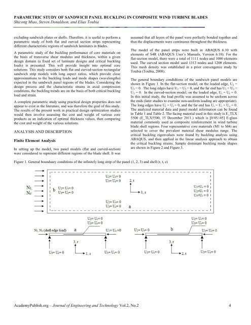
The general boundary condidtions of the sandwich panel models are<br />
shown <strong>in</strong> Figure 1. In the flat-section model, on the loaded edge, U 2 =<br />
U 3 = 0. The long edges have U 2 = U 3 = 0, and the far end has U 1 = U 2 =<br />
U 3 = 0. In the curved-section model, on the loaded edge, U t = U r = 0.<br />
In this <strong>in</strong>itial study, the load profile was assumed to be uni<strong>form</strong> across<br />
the ends (later studies to exam<strong>in</strong>e non-uni<strong>form</strong> load<strong>in</strong>g are appropriate).<br />
The long edges have U t = U r = 0, and the far end has U t = U r = U z = 0.<br />
The analyzed material data and panel model <strong>in</strong><strong>form</strong>ation can be found<br />
<strong>in</strong> Table 1 and Table 2. The fac<strong>in</strong>g material used <strong>in</strong> this study is E_TLX<br />
5500 ( E_TLX5500, 15 December 2011.) which is [0/45/-45] E-glass<br />
material commonly used as composite re<strong>in</strong>forcement <strong>in</strong> w<strong>in</strong>d turb<strong>in</strong>e<br />
blade shell regions. Four representative core materials (M1 to M4) are<br />
selected to cover the prevalent material shear modulus range. The<br />
critical buckl<strong>in</strong>g eigenvalues were found by buckl<strong>in</strong>g analysis us<strong>in</strong>g<br />
ABAQUS, and then applied <strong>in</strong> the l<strong>in</strong>ear analysis approach to obta<strong>in</strong><br />
the critical buckl<strong>in</strong>g stra<strong>in</strong>s. Sample dom<strong>in</strong>ant buckl<strong>in</strong>g mode shapes<br />
are shown <strong>in</strong> Figure 2 and Figure 3.<br />
Figure 1. General bounduary conditions of the <strong>in</strong>f<strong>in</strong>itely long strip of the panel (1, 2, 3) and shell (r, t, z)<br />
<strong>Academy</strong><strong>Publish</strong>.org – Journal of Eng<strong>in</strong>eer<strong>in</strong>g and Technology Vol.2, No.2 4