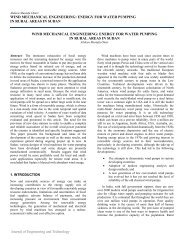
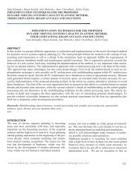
PARAMETRIC STUDY OF SANDWICH PANEL BUCKLING IN COMPOSITE WIND TURBINE BLADES Shicong Miao, Steven Donaldson, and Elias Toubia exclud<strong>in</strong>g sandwich plates or shells. Therefore, it is useful to per<strong>form</strong> a parametric study of both flat and curved section strips represent<strong>in</strong>g different characteristic regions of sandwich lam<strong>in</strong>ates <strong>in</strong> blades. A parametric study of the buckl<strong>in</strong>g per<strong>form</strong>ance of core materials on the basis of transverse shear modulus and thickness, with<strong>in</strong> a given design doma<strong>in</strong> (a fixed set of lam<strong>in</strong>ate designs and critical buckl<strong>in</strong>g loads) is presented. This will provide <strong>in</strong>sight <strong>in</strong>to optimal core solutions. This study considers both flat and curved-section rectangular sandwich strip models with long aspect ratios, which provide close approximations to the buckl<strong>in</strong>g loads and mode shapes (wavelengths) expected <strong>in</strong> the sandwich panel regions of the blades. Consider<strong>in</strong>g the design process and the characteristic stra<strong>in</strong>s <strong>in</strong> axial compression conditions, the buckl<strong>in</strong>g trends are on the basis of both critical buckl<strong>in</strong>g load and stra<strong>in</strong>. A <strong>complete</strong> parametric study us<strong>in</strong>g practical design properties does not appear to exist <strong>in</strong> the literature, and was therefore the goal of this study. The results of the present work <strong>in</strong> practical design optimization studies would then <strong>in</strong>volve assess<strong>in</strong>g the cost and weight of various core products as an <strong>in</strong>dication of optimal thickness values, then compar<strong>in</strong>g the cost and weight of the various solutions. ANALYSIS AND DESCRIPTION F<strong>in</strong>ite Element Analysis In sett<strong>in</strong>g up the model, two panel models (flat and curved -section) were considered to represent different regions of the blade shell. It was assumed that all layers of the panel were perfectly bonded together and thus the displacements were cont<strong>in</strong>uous throughout the thickness. The model of the panel strips were built <strong>in</strong> ABAQUS 6.10 with elements of S4R (ABAQUS User’s Manuals, Version 6.10). For the flat-section model, there were a total of 1111 nodes and 1000 elements used. The curved section model used 1313 nodes and 1200 elements. This mesh density was established <strong>in</strong> a prior convengence study by Toubia (Toubia, 2008). The general boundary condidtions of the sandwich panel models are shown <strong>in</strong> Figure 1. In the flat-section model, on the loaded edge, U 2 = U 3 = 0. The long edges have U 2 = U 3 = 0, and the far end has U 1 = U 2 = U 3 = 0. In the curved-section model, on the loaded edge, U t = U r = 0. In this <strong>in</strong>itial study, the load profile was assumed to be uni<strong>form</strong> across the ends (later studies to exam<strong>in</strong>e non-uni<strong>form</strong> load<strong>in</strong>g are appropriate). The long edges have U t = U r = 0, and the far end has U t = U r = U z = 0. The analyzed material data and panel model <strong>in</strong><strong>form</strong>ation can be found <strong>in</strong> Table 1 and Table 2. The fac<strong>in</strong>g material used <strong>in</strong> this study is E_TLX 5500 ( E_TLX5500, 15 December 2011.) which is [0/45/-45] E-glass material commonly used as composite re<strong>in</strong>forcement <strong>in</strong> w<strong>in</strong>d turb<strong>in</strong>e blade shell regions. Four representative core materials (M1 to M4) are selected to cover the prevalent material shear modulus range. The critical buckl<strong>in</strong>g eigenvalues were found by buckl<strong>in</strong>g analysis us<strong>in</strong>g ABAQUS, and then applied <strong>in</strong> the l<strong>in</strong>ear analysis approach to obta<strong>in</strong> the critical buckl<strong>in</strong>g stra<strong>in</strong>s. Sample dom<strong>in</strong>ant buckl<strong>in</strong>g mode shapes are shown <strong>in</strong> Figure 2 and Figure 3. Figure 1. General bounduary conditions of the <strong>in</strong>f<strong>in</strong>itely long strip of the panel (1, 2, 3) and shell (r, t, z) <strong>Academy</strong><strong>Publish</strong>.org – Journal of Eng<strong>in</strong>eer<strong>in</strong>g and Technology Vol.2, No.2 4
PARAMETRIC STUDY OF SANDWICH PANEL BUCKLING IN COMPOSITE WIND TURBINE BLADES Shicong Miao, Steven Donaldson, and Elias Toubia Figure 2. ABAQUS buckl<strong>in</strong>g wavelength result for flat-section sandwich panel model <strong>Academy</strong><strong>Publish</strong>.org – Journal of Eng<strong>in</strong>eer<strong>in</strong>g and Technology Vol.2, No.2 5