PRP1766 Star Trek: Enterprise Phase Pistol ... - Roddenberry.com
PRP1766 Star Trek: Enterprise Phase Pistol ... - Roddenberry.com
PRP1766 Star Trek: Enterprise Phase Pistol ... - Roddenberry.com
You also want an ePaper? Increase the reach of your titles
YUMPU automatically turns print PDFs into web optimized ePapers that Google loves.
#<strong>PRP1766</strong><br />
<strong>Star</strong> <strong>Trek</strong>: <strong>Enterprise</strong> <strong>Phase</strong> <strong>Pistol</strong><br />
Prop Kit Assembly Manual<br />
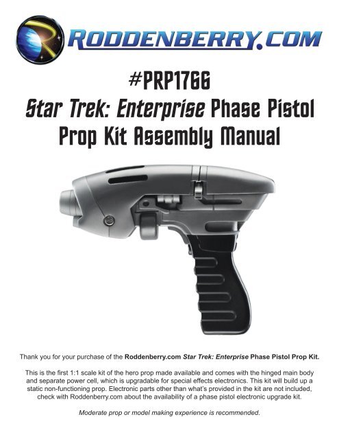
Thank you for your purchase of the <strong>Roddenberry</strong>.<strong>com</strong> <strong>Star</strong> <strong>Trek</strong>: <strong>Enterprise</strong> <strong>Phase</strong> <strong>Pistol</strong> Prop Kit.<br />
This is the first 1:1 scale kit of the hero prop made available and <strong>com</strong>es with the hinged main body<br />
and separate power cell, which is upgradable for special effects electronics. This kit will build up a<br />
static non-functioning prop. Electronic parts other than what’s provided in the kit are not included,<br />
check with <strong>Roddenberry</strong>.<strong>com</strong> about the availability of a phase pistol electronic upgrade kit.<br />
Moderate prop or model making experience is re<strong>com</strong>mended.
2<br />
#<strong>PRP1766</strong> - STAR TREK: En t e r p r is e Ph a s e Pis t o l Pr o p Kit As s e m b l y Ma n u a l<br />
BASIC INVENTORY:<br />
Resin casting:<br />
Main Receiver<br />
Rear Top<br />
Interior Plate<br />
Force Setting Sliders<br />
(left and right)<br />
Hinged Hood<br />
Emitter<br />
<strong>Pistol</strong> Grip<br />
Trigger<br />
Power Cell<br />
(left, right, and end cap<br />
clear-cast shells)<br />
Power Cell Stop Block<br />
Dovetail Plate<br />
Other parts, <strong>Phase</strong> <strong>Pistol</strong>:<br />
2 @ 8-32 hinge screws<br />
with bent wire tool<br />
2 @ grip securing screws<br />
3 @ 1/4” magnets<br />
5 @ laser-cut black plastic<br />
oval strips<br />
Foam piece for trigger<br />
Interior graphics<br />
Clear emitter insert with silver tape<br />
Other Parts, Power Cell:<br />
Micro-push switch<br />
Brass power cell plate with 2-56 screw<br />
Chrome graphic detailing<br />
Materials needed:<br />
Cyanoacrylate (CA) glue with fast-cure accelerator<br />
Automotive or hobby spot putty filler<br />
Masking tape (blue painter’s tape re<strong>com</strong>mended)<br />
Epoxy glue (5-minute type re<strong>com</strong>mended)<br />
Optional: Bondo<br />
2 @ AAAA batteries<br />
Tools needed:<br />
Hobby knife (X-Acto brand or similar)<br />
Sandpaper (220-320 grit rough, 400-600 grit finish)<br />
Files and/or sanding sticks<br />
Drill with a #20 bit (or 5/32”) and 1/8” bits<br />
8-32 tap with tap handle<br />
Small Philips screwdriver<br />
Standard or needlenose pliers<br />
Paints needed (all spray cans):<br />
Gray primer (sandable-type)<br />
Semi-Gloss Black<br />
Testors Model<br />
Master Magnesium Metalizer (#1453) and<br />
Titanium Metalizer (#1454 - small cans)<br />
Testors Aluminum<br />
Plate Metalizer (or Krylon Dull Aluminum)<br />
Testors Metalizer Sealer or Testors Dullcote<br />
(all Testors paints available at hobby stores)
#<strong>PRP1766</strong> - STAR TREK: En t e r p r is e Ph a s e Pis t o l Pr o p Kit As s e m b l y Ma n u a l 3<br />
Preparation:<br />
These instructions are for building up a non-functioning static prop. If you are thinking of<br />
installing an electronics upgrade kit, note that once parts are glued together, you may not<br />
be able to get the parts apart without damaging them if you change your mind later.<br />
Step 0:<br />
<strong>Star</strong>t by sanding the mold lines and flashing from all the resin parts, using your tools at hand: sandpaper,<br />
files, sanding sticks, knife, etc., and try not to eat into the details too much [Fig. 1]. Use spot putty to fill in<br />
any obvious marks or holes and sand smooth. Test fit your parts to make sure they all work. [Fig. 2].
4<br />
#<strong>PRP1766</strong> - STAR TREK: En t e r p r is e Ph a s e Pis t o l Pr o p Kit As s e m b l y Ma n u a l<br />
Step 1:<br />
Drill with a 1/8” bit into the two side-by-side divots in the receiver from the bottom. These are the clearance<br />
holes that will secure the grip [Fig. 3]. Screw the grip onto the body with the two Philips head screws to try<br />
it out [Fig. 4], then remove the grip and set aside.<br />
Step 2:<br />
Apply the foam piece to the back of the trigger button, then try the trigger out in the grip. Remove the trigger<br />
and set aside.<br />
Step 3:<br />
CA glue the power cell stop block to the inside of the hinged hood as shown. Make sure it is flat on the<br />
surface but all the way up...since it needs to stay out of the way of the receiver’s hinging point [Fig. 5].<br />
Glue one of the magnets in the hole, direction doesn’t matter. Take the dovetail block and try sliding in the<br />
power cell assembly, regardless if you’ve assembled it first or not. If there is difficulty in this, it will be easier<br />
to sand the inside dovetail angles and the outer slotted surface before it gets glued to the hood [Fig. 6]. So<br />
make sure the power cell will slide easily before gluing on the dovetail, taking into account the thickness of<br />
the paint you’ll be applying.
#<strong>PRP1766</strong> - STAR TREK: En t e r p r is e Ph a s e Pis t o l Pr o p Kit As s e m b l y Ma n u a l 5<br />
Step 4:<br />
Drill two holes for the hinge screws into the hood, using a #20 (.161”) bit [Fig. 7]. A <strong>com</strong>mon 5/32” bit may<br />
be used, but be sure the hinge screws (the ones with the two holes on top) go in the holes loosely. Use a<br />
round file to make the holes a little bigger, if needed. The hinged hood will be hinging on the screws, so try<br />
not to make these holes too big.<br />
Step 5:<br />
Place the rear top on the receiver; use tape too hold it in place. Place the hinged hood on the receiver<br />
where it is supposed to go for the best look -- flat on the receiver and back to the rear top, making sure the<br />
parts appear smooth to each other. Use 4-5 thicknesses of ordinary paper at the top joint to create a small<br />
gap there -- the graphic details have a thickness to them that will interfere with proper closure if you don’t<br />
have a gap [Fig. 8].
6<br />
#<strong>PRP1766</strong> - STAR TREK: En t e r p r is e Ph a s e Pis t o l Pr o p Kit As s e m b l y Ma n u a l<br />
Step 6:<br />
Draw a mark in both hinge holes on the receiver; or if you have a center punch available or something<br />
pointy, you may punch a mark in the center of the hinge holes that will locate where the drill bit needs to go<br />
[Fig. 9]. Remove the hood [Fig, 10].<br />
Note: if you have a receiver where there are large divot marks already in place, check with the hood<br />
in place to see if you have perfect alignment -- if not, you will need to fill in the divots with Bondo,<br />
sand flat after it hardens <strong>com</strong>pletely, and proceed as stated in the last paragraph.<br />
Step 7:<br />
Drill a 1/8” hole in both ends of the receiver hinge point. Do not attempt to make this a through hole, but<br />
they do need to go in approx. 3/8”. Be very sure you drill these in straight, as any angling can affect how the<br />
hinging action works or how much meat you have in the hinge point for the screws [Fig. 11].
#<strong>PRP1766</strong> - STAR TREK: En t e r p r is e Ph a s e Pis t o l Pr o p Kit As s e m b l y Ma n u a l 7<br />
Step 8:<br />
It is re<strong>com</strong>mended that you get a 8-32 tap with a tap handle to thread these holes so the hinge screws can<br />
be secured; these are available at any hardware store. Tap the holes [Fig. 12], using water for lubrication<br />
if necessary, then put the hood back on and thread in the hinge screws using the bent wire tool with pliers<br />
[Fig. 13].<br />
You have the option of purchasing the “Drill Master 100 Piece Security Bit Set” available at Harbor Freight<br />
Tools [#SKU91310], which will have the right #8 “spanner” driver bit for these screws. A specialty tool store<br />
might carry a screwdriver for this screw--one that’s available is marked “TAMPER-PRUF #8.”<br />
Note: Be careful when tapping into the holes and inserting the screws, as plastic threading is very<br />
fragile and easily stripped. If your holes end up stripped or too big for threading the screws in,<br />
you will need to fill the holes with bondo and/or glue and try again, or use some other means of<br />
repairing your threads.<br />
Step 9:<br />
Slide the power cell in place inside the hood if it is already assembled (or tape it together; it will need its end<br />
cap in place), then close the hood and see if the power cell interferes with the hood closing. If so, there are<br />
several fixes you can do: sand the affected areas on the rear top, sand the power cell fingergrip where it<br />
hits, or try to fix the hinge holes as these might be set at a slight angle [Fig. 14]. You should also sand any<br />
place where plastic may be rubbing against plastic on the hinge joint since that’s where paint will rub off, but<br />
be careful you don’t sand too much since you can affect the overall look of the phase pistol.<br />
When it’s all good, remove the hood and all the other loose parts.
8<br />
#<strong>PRP1766</strong> - STAR TREK: En t e r p r is e Ph a s e Pis t o l Pr o p Kit As s e m b l y Ma n u a l<br />
Step 10:<br />
Glue the two remaining magnets to the hole in the rear top body and the hole on the hinged hood. To insure<br />
the magnets are attracting, glue one magnet in one part. Stick the loose magnet on your glued magnet and<br />
mark the exposed end with a marker [Fig. 15] -- this is the end that will go into the hole in the other part<br />
-- if you see your marker ink, turn the magnet around then glue in place [Fig. 16].<br />
Put masking tape on the inside dovetail angles to protect from overspray that may interfere with sliding the<br />
power cell in.<br />
Painting THe <strong>Phase</strong> <strong>Pistol</strong><br />
Also see Figs. 20, 21, and 22 for more<br />
painted images of the final <strong>Phase</strong> <strong>Pistol</strong>.<br />
Step 11:<br />
Paint the interior plate either Testors Aluminum Plate Metalizer or Krylon Dull Aluminum. The receiver unit,<br />
the rear top body, the force setting sliders, the hinged hood, and the emitter are sprayed in Testors Model<br />
Master Magnesium Metalizer [#1453]. Spray both exterior and interior, then set aside and let cure at least<br />
several hours or overnight.<br />
Note: Testors Metalizer painted parts can be clear coated, but only use their re<strong>com</strong>mended lacquerbased<br />
Testors Sealer For Metalizer and/or Testors Dullcote -- do not use Krylon Matte Finish or<br />
other enamel based clear coatings. If you happen to use other enamel paints for your colors, note<br />
that lacquers should not be painted over enamels as you could damage your paint. Or you can<br />
leave the metalizer finish alone, and over time, portions may “buff” out from handling your prop to<br />
create a more “machined metal” or “polished metal” look.
#<strong>PRP1766</strong> - STAR TREK: En t e r p r is e Ph a s e Pis t o l Pr o p Kit As s e m b l y Ma n u a l 9<br />
Step 12:<br />
After the hinged hood is dry enough so it will survive masking tape (wait several hours if necessary), apply<br />
masking tape to the areas at both ends of the hood [Figs. 18, 19], be sure the emitter and the hood interior<br />
are protected from overspray, but make sure the edges are exposed. Spray Testors Model Master Titanium<br />
Metalizer [#1454] on the exposed portions of the hood...and when dry, remove the masking. This part may<br />
be painted in reverse if you think it will be easier to mask: paint the Titanium first, mask the middle area and<br />
the edges the opposite of the pictures, then spray Magnesium.<br />
The sample pistol illustrated above has the round protrusion at the bottom of the receiver painted in<br />
Titanium. You may either mask and paint this part or leave in the lighter Magnesium as a personal<br />
preference...as both are accurate.
10<br />
#<strong>PRP1766</strong> - STAR TREK: En t e r p r is e Ph a s e Pis t o l Pr o p Kit As s e m b l y Ma n u a l<br />
Assembly:<br />
Step 13:<br />
Screw the pistol grip/trigger assembly to the receiver (be sure it’s secure, use glue if needed), then glue on<br />
the receiver interior plate.<br />
Apply the graphics as shown on the graphics page [see Page 13]. It may be easier to do this step while the<br />
parts are still separated.<br />
Screw the hood on and insert the power cell, and put in the two slide switches. Try the hood to see if<br />
anything interferes and if so, sand and/or adjust the affected part(s); you may need to repaint some parts<br />
if necessary. Be sure the hinge screws are only tight enough to allow easy hinging action without them<br />
being stuck out.<br />
Place the rear top on, and note how it lines up with the hood -- try raising and lowering the hood, then glue<br />
the rear top in place on the receiver. Be careful the magnets aren’t raising the rear end off the receiver.<br />
Step 14:<br />
Apply the last silver dot to the flat end of the clear emitter insert, trim away any excess [Fig. 24], then glue it<br />
with epoxy into the emitter hole, pushing it in until it’s flush with the emitter end [Figs. 23, 25]. The dot helps<br />
a lot in making the emitter reflect light on its own, but is not used if you’re installing a working light.<br />
Step 15:<br />
Glue the emitter onto the hood, and glue the five plastic strips to the upper slots on the hinged hood [Fig.<br />
22], and the pistol is finished.
#<strong>PRP1766</strong> - STAR TREK: En t e r p r is e Ph a s e Pis t o l Pr o p Kit As s e m b l y Ma n u a l 11<br />
Power Cell Assembly:<br />
NOTE:<br />
If you are planning on making a functioning Power Cell, you will need to inquire with <strong>Roddenberry</strong>.<strong>com</strong><br />
about the availability of an electronic upgrade kit; there are no electronic parts included with this prop kit<br />
other than the micro push button switch that is a part of the detailing. As with the pistol prop; if you<br />
glue the power cell parts together as they <strong>com</strong>e in this kit, you will not be able to get them apart<br />
again without damage if you decide you want working lights in it later.<br />
For a non-working static power cell:<br />
After removing mold lines and so forth from all the resin parts, test fit the two shells in the dovetail block.<br />
This should slide in easily. If it doesn’t, be sure the two shell halves are fitting together well before you sand<br />
either the male or female dovetails. If it’s all working, glue the left and right shells together, and glue the end<br />
cap on. Glue the microswitch in place: the switch body should stick out approximately 1/32” forward. But be<br />
sure the power cell can still be inserted all the way; if the switch is out too far, you might not be able to close<br />
the pistol hood [Fig. 26].<br />
Mask the two ribbed tube details with masking tape...these are clear in the finished prop [Fig. 27]. Mask the<br />
switch rod and stick masking into the two battery holes so paint doesn’t sneak inside, leaving everything<br />
else exposed. Spray primer the power cell and the brass “V” piece, then spray both parts in Magnesium<br />
Metalizer; and when dry, apply the chrome graphic detail tape as shown on the graphics page [Page 13].
12<br />
#<strong>PRP1766</strong> - STAR TREK: En t e r p r is e Ph a s e Pis t o l Pr o p Kit As s e m b l y Ma n u a l<br />
Lastly, screw on the brass “V” piece using the 2-56 Philips flat head screw [Fig. 28].<br />
For added detail, you may install two AAA batteries. But if you don’t have an electronics upgrade kit, you<br />
won’t get the terminal springs to push the batteries out where they should be -- they are not included with<br />
the standard build-up kit. You can get a pair of springs and put them in, or glue the batteries in permanently,<br />
or wrap a little masking tape around the batteries and shove them in that way. But note that if you do any of<br />
that, it may be impossible to get the batteries out again -- batteries in a non-functional power cell serve as<br />
added detailing only [Fig. 28].<br />
Insert the power cell, close the hood, and your <strong>Star</strong> <strong>Trek</strong>: <strong>Enterprise</strong> <strong>Phase</strong> <strong>Pistol</strong> is finished!<br />
IMPORTANT NOTES:<br />
The physical reproduction by any means known or yet to be invented (including molding<br />
and recasting, reverse-engineering, and stereo lithography scanning and printing) of this<br />
<strong>Roddenberry</strong>.<strong>com</strong> <strong>Star</strong> <strong>Trek</strong>: <strong>Enterprise</strong> <strong>Phase</strong> <strong>Pistol</strong> Prop Kit or its parts and graphics, or<br />
reproducing any pre-existing parts and graphics, is expressly prohibited under U.S. and<br />
international copyright and product protection laws.<br />
Copyright © 2009 <strong>Roddenberry</strong> Productions.<br />
<strong>Star</strong> <strong>Trek</strong> and related marks and logos are Trademarks of CBS Studios Inc. All rights reserved.
#<strong>PRP1766</strong> - STAR TREK: En t e r p r is e Ph a s e Pis t o l Pr o p Kit As s e m b l y Ma n u a l 13<br />
Graphics Placement:<br />
Place the dashed sticker on the interior plate, the “target” sticker on the power cell stop block’s magnet, and<br />
one chrome dot above it and just under the dovetail’s end [Fig. G1].<br />
Place one chrome dot each on the other two magnets on the hood and the rear top, and on their<br />
corresponding areas for symmetry; one black rectangle each on the two force setting sliders and their<br />
opposite areas on the hood; and the 1” chrome strip on the hood above the dovetail [Figs. G2 and G3].<br />
On the power cell, place the 2” chrome strips on the two major sides, and the chrome square in the middle<br />
of the thumbgrip end [Fig. G4].


