

Optimal Design of LCL Harmonic Filters for Three-Phase PFC ...
Optimal Design of LCL Harmonic Filters for Three-Phase PFC ...
Optimal Design of LCL Harmonic Filters for Three-Phase PFC ...

Create successful ePaper yourself
Turn your PDF publications into a flip-book with our unique Google optimized e-Paper software.
MÜHLETHALER et al.: OPTIMAL DESIGN OF <strong>LCL</strong> HARMONIC FILTERS FOR THREE-PHASE <strong>PFC</strong> RECTIFIERS 3115<br />
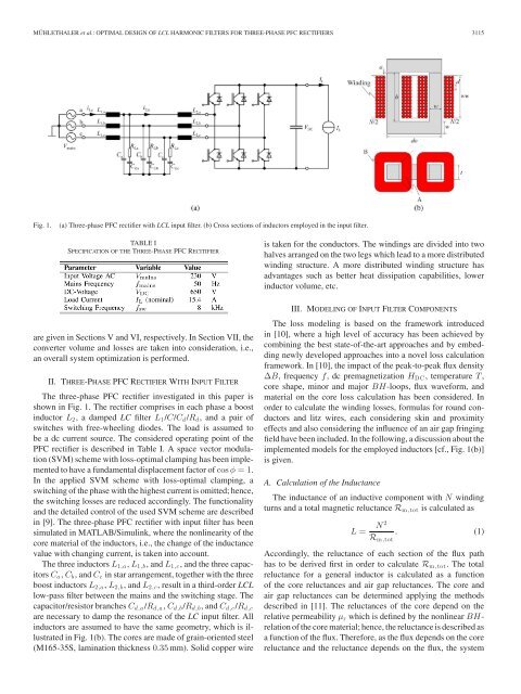
Fig. 1.<br />
(a) <strong>Three</strong>-phase <strong>PFC</strong> rectifier with <strong>LCL</strong> input filter. (b) Cross sections <strong>of</strong> inductors employed in the input filter.<br />
TABLE I<br />
SPECIFICATION OF THE THREE-PHASE <strong>PFC</strong> RECITIFIER<br />
is taken <strong>for</strong> the conductors. The windings are divided into two<br />
halves arranged on the two legs which lead to a more distributed<br />
winding structure. A more distributed winding structure has<br />
advantages such as better heat dissipation capabilities, lower<br />
inductor volume, etc.<br />
are given in Sections V and VI, respectively. In Section VII, the<br />
converter volume and losses are taken into consideration, i.e.,<br />
an overall system optimization is per<strong>for</strong>med.<br />
II. THREE-PHASE <strong>PFC</strong> RECTIFIER WITH INPUT FILTER<br />
The three-phase <strong>PFC</strong> rectifier investigated in this paper is<br />
shown in Fig. 1. The rectifier comprises in each phase a boost<br />
inductor L 2 , a damped LC filter L 1 /C/C d /R d , and a pair <strong>of</strong><br />
switches with free-wheeling diodes. The load is assumed to<br />
be a dc current source. The considered operating point <strong>of</strong> the<br />
<strong>PFC</strong> rectifier is described in Table I. A space vector modulation<br />
(SVM) scheme with loss-optimal clamping has been implemented<br />
to have a fundamental displacement factor <strong>of</strong> cos φ =1.<br />
In the applied SVM scheme with loss-optimal clamping, a<br />
switching <strong>of</strong> the phase with the highest current is omitted; hence,<br />
the switching losses are reduced accordingly. The functionality<br />
and the detailed control <strong>of</strong> the used SVM scheme are described<br />
in [9]. The three-phase <strong>PFC</strong> rectifier with input filter has been<br />
simulated in MATLAB/Simulink, where the nonlinearity <strong>of</strong> the<br />
core material <strong>of</strong> the inductors, i.e., the change <strong>of</strong> the inductance<br />
value with changing current, is taken into account.<br />
The three inductors L 1,a , L 1,b , and L 1,c , and the three capacitors<br />
C a , C b , and C c in star arrangement, together with the three<br />
boost inductors L 2,a , L 2,b , and L 2,c , result in a third-order <strong>LCL</strong><br />
low-pass filter between the mains and the switching stage. The<br />
capacitor/resistor branches C d,a /R d,a , C d,b /R d,b , and C d,c /R d,c<br />
are necessary to damp the resonance <strong>of</strong> the LC input filter. All<br />
inductors are assumed to have the same geometry, which is illustrated<br />
in Fig. 1(b). The cores are made <strong>of</strong> grain-oriented steel<br />
(M165-35S, lamination thickness 0.35 mm). Solid copper wire<br />
III. MODELING OF INPUT FILTER COMPONENTS<br />
The loss modeling is based on the framework introduced<br />
in [10], where a high level <strong>of</strong> accuracy has been achieved by<br />
combining the best state-<strong>of</strong>-the-art approaches and by embedding<br />
newly developed approaches into a novel loss calculation<br />
framework. In [10], the impact <strong>of</strong> the peak-to-peak flux density<br />
ΔB, frequency f, dc premagnetization H DC , temperature T ,<br />
core shape, minor and major BH-loops, flux wave<strong>for</strong>m, and<br />
material on the core loss calculation has been considered. In<br />
order to calculate the winding losses, <strong>for</strong>mulas <strong>for</strong> round conductors<br />
and litz wires, each considering skin and proximity<br />
effects and also considering the influence <strong>of</strong> an air gap fringing<br />
field have been included. In the following, a discussion about the<br />
implemented models <strong>for</strong> the employed inductors [cf., Fig. 1(b)]<br />
is given.<br />
A. Calculation <strong>of</strong> the Inductance<br />
The inductance <strong>of</strong> an inductive component with N winding<br />
turns and a total magnetic reluctance R m,tot is calculated as<br />
L = N 2<br />
R m,tot<br />
. (1)<br />
Accordingly, the reluctance <strong>of</strong> each section <strong>of</strong> the flux path<br />
has to be derived first in order to calculate R m,tot . The total<br />
reluctance <strong>for</strong> a general inductor is calculated as a function<br />
<strong>of</strong> the core reluctances and air gap reluctances. The core and<br />
air gap reluctances can be determined applying the methods<br />
described in [11]. The reluctances <strong>of</strong> the core depend on the<br />
relative permeability μ r which is defined by the nonlinear BHrelation<br />
<strong>of</strong> the core material; hence, the reluctance is described as<br />
a function <strong>of</strong> the flux. There<strong>for</strong>e, as the flux depends on the core<br />
reluctance and the reluctance depends on the flux, the system


