Nice Robus Kit 1 - Rolling Center
Nice Robus Kit 1 - Rolling Center
Nice Robus Kit 1 - Rolling Center

Create successful ePaper yourself
Turn your PDF publications into a flip-book with our unique Google optimized e-Paper software.
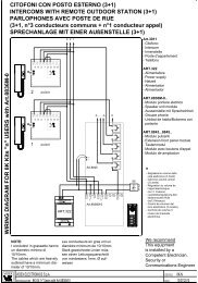
If the rack is already present, once the gearmotor has been fastened,<br />
use the adjustment dowels as shown in Figure 8 to set the pinion of<br />
ROBUS to the right height, leaving 1÷2 mm of play from the rack.<br />
Otherwise, in order to fasten the rack the installer must:<br />
6. Release the gearmotor as shown in “Release and manual movement”<br />
paragraph in the Chapter “Instructions and Warnings for<br />
users of the ROBUS gearmotor”.<br />
7. Open the leaf up completely and place the first piece of the rack<br />
on the pinion. Check that the beginning of the rack corresponds<br />
to the beginning of the leaf, as shown in Figure 9. Leave a 1÷2<br />
mm play between the rack and the pinion, then fasten the rack to<br />
the leaf using suitable means.<br />
1÷2<br />
8 9 10<br />
11 12<br />
! In order to prevent the weight of the leaf from affecting the<br />
gearmotor, it is important that there is a play of 1÷2 mm between<br />
the rack and the pinion as shown in Figure 10.<br />
8. Slide the leaf, using the pinion as a reference point for the fastening<br />
the other elements of the rack.<br />
9. Cut away the exceeding part of the rack.<br />
10. Open and close the gate several times and make sure that the rack<br />
is aligned with the pinion with a maximum tolerance of 5 mm. Moreover,<br />
check that the play of 1÷2 mm has been respected along the<br />
entire length between the pinion and the rack.<br />
11. Thoroughly tighten the two fixing nuts of the gearmotor making sure<br />
it is well fastened to the ground. Cover the fixing nuts with the relative<br />
caps as shown in figure 11.<br />
12. Fix the limit switch bracket as described below (for versions<br />
RB600P and RB1000P, fix the bracket as described in paragraph<br />
“3.3 Fixing of the limit switch bracket on versions with inductive limit<br />
switch”):<br />
• Manually place the leaf in the open position leaving at least 2-3 cm<br />
from the mechanical stop.<br />
• Slide the bracket along the rack in the opening direction until the<br />
limit switch cuts-in. Then bring the bracket forward by at least 2<br />
cm and secure it to the rack with the appropriate dowels, as in fig.<br />
12.<br />
• Perform the same operation for the closure limit switch.<br />
13. Lock the gearmotor as shown in “Release and manual movement”<br />
paragraph in the Chapter “Instructions and Warnings for Users”<br />
3.3) Fixing of the limit switch bracket on versions with inductive limit switch<br />
The limit switch bracket must be fixed as described below for the<br />
RB600P and RB1000P versions that utilise the inductive limit switch.<br />
1. Manually place the leaf in the open position leaving at least<br />
2-3 cm from the mechanical stop.<br />
2. Slide the bracket along the rack in the opening direction until the<br />
corresponding LED switches off, as in fig. 13. Then bring the<br />
bracket forward by at least 2 cm and secure it to the rack with the<br />
appropriate dowels.<br />
3. Manually place the leaf in the closed position leaving at least 2-3<br />
cm from the mechanical stop<br />
4. Slide the bracket along the rack in the closing direction until the<br />
corresponding LED switches off. Then bring the bracket forward<br />
by at least 2 cm and secure it to the rack with the appropriate<br />
dowels.<br />
! The ideal distance of the bracket for inductive limit switches<br />
is between 3 and 8 mm as indicated in fig. 14.<br />
13<br />
14<br />
3÷8<br />
8