Nice Robus Kit 1 - Rolling Center
Nice Robus Kit 1 - Rolling Center
Nice Robus Kit 1 - Rolling Center

You also want an ePaper? Increase the reach of your titles
YUMPU automatically turns print PDFs into web optimized ePapers that Google loves.
7.3.5) ROBUS in “Slave” mode<br />
Properly programming and connecting, ROBUS can function in<br />
“Slave” mode; this type of function is used when 2 opposite gates<br />
need to be automated with the synchronised movement of the two<br />
leaves. In this mode ROBUS works as Master commanding the<br />
movement, while the second ROBUS acts as Slave, following the<br />
commands transmitted by the Master (all ROBUS are Masters when<br />
leaving the factory).<br />
To configure ROBUS as a Slave the level one “Slave mode” must be<br />
activated (see table 7).<br />
The connection between ROBUS Master and ROBUS Slave is made<br />
via BlueBus.<br />
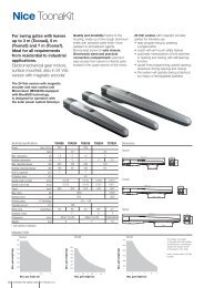
! In this case the polarity of the connections between<br />
the two ROBUS must be respected as illustrated in fig. 26<br />
(the other devices remain with no polarity).<br />
Follow the operations below to install 2 ROBUS in the Master and<br />
Slave mode:<br />
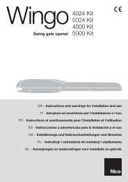
• Install the 2 motors as indicated in fig. 25. It is not important which<br />
motor is to function as Slave or Master; when choosing, one must<br />
consider the convenience of the connections and the fact that the<br />
Step-by-Step command of the Slave only allows the Slave leaf to<br />
be opened fully.<br />
25<br />
• Connect the 2 motors as shown in fig. 26.<br />
• Select the opening direction of the 2 motors as shown in fig. 25<br />
(see also paragraph “4.1 Choosing the direction”).<br />
• Supply power to the 2 motors.<br />
• Program the “Slave mode” on the ROBUS Slave (see table 7).<br />
• Perform the device recognition on the ROBUS Slave (see paragraph<br />
“4.3 Recognition of the devices”).<br />
• Perform the device recognition on the ROBUS Master (see paragraph<br />
“4.3 Recognition of the devices”).<br />
• Perform the recognition of the leaf length on the ROBUS Master<br />
(see paragraph “4.4 Recognition length of the leaf”).<br />
LUCYB<br />
LUCYB<br />
S.C.A. MOFB OPEN CLOSE MOSE<br />
S.C.A. STOP PP<br />
26<br />
When connecting 2 ROBUS in the Master-Slave mode, pay attention that:<br />
• All devices must be connected to the ROBUS Master (as in fig. 26) including the radio receiver.<br />
• When using buffer batteries, each motor must have its own battery.<br />
• All programming performed on ROBUS Slave are ignored (those on ROBUS Master override the others) except for those mentioned in table 14.<br />
18