Nice Robus Kit 1 - Rolling Center
Nice Robus Kit 1 - Rolling Center
Nice Robus Kit 1 - Rolling Center

Create successful ePaper yourself
Turn your PDF publications into a flip-book with our unique Google optimized e-Paper software.
3.6) Description of the electrical connections<br />
The following is a brief description of the electrical connections; for<br />
further information please read “7.3 Adding or Removing Devices”<br />
paragraph.<br />
FLASH: output for one or two “LUCYB” or similar type flashing<br />
lights with single 12V maximum 21W bulb.<br />
S.C.A.: “Open Gate Light” output. An indication lamp can be connected<br />
(24V max. 4W). It can also be programmed for other functions;<br />
see paragraph “7.2.3 Level two functions”.<br />
BLUEBUS: compatible devices can be connected up to this terminal.<br />
They are connected in parallel using two conductors only,<br />
through which both the electricity supply and the communication<br />
signals travel. For more useful information about BlueBUS see also<br />
Paragraph “7.3.1 BlueBUS”.<br />
STOP: input for the devices which block or eventually stop the<br />
manoeuvre in progress. Contacts like “Normally Closed”, “Normally<br />
Open” or constant resistance devices can be connected up using<br />
special procedures on the input. For more useful information about<br />
STOP see also Paragraph “7.3.2 STOP Input”.<br />
STEP-BY-STEP: input for devices which control Step-by-Step<br />
movement. It is possible to connect “Normally Open” devices up to<br />
this input.<br />
OPEN: input for devices which control only the opening movement.<br />
It is possible to connect “Normally Open” devices up to this<br />
input.<br />
CLOSE: input for devices which control only the closing movement.<br />
It is possible to connect “Normally Open” devices up to this<br />
input.<br />
AERIAL: connection input for the radio receiver aerial (the aerial is<br />
incorporated in LUCY B).<br />
4) Final checks and start up<br />
The manufacturers recommend you position the leaf at approximately half travel before starting the checking and start up phase of the<br />
automation. This will ensure the leaf is free to move both during opening and closure.<br />
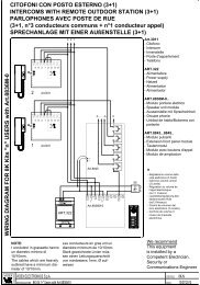
4.1) Choosing the direction<br />
The direction of the opening manoeuvre must be chosen depending<br />
on the position of the gearmotor with respect to the leaf. If the leaf<br />
must move left for opening, the selector must be moved towards left<br />
as shown in Figure 18; alternatively, if the leaf has to move right during<br />
opening, the selector must be moved towards the right as shown<br />
in Figure 19<br />
18<br />
19<br />
4.2) Power supply connection<br />
! The connection of ROBUS to the mains must be made<br />
by qualified and experienced personnel in possession of<br />
the necessary requisites and in full respect of the laws,<br />
provisions and standards currently in force.<br />
As soon as ROBUS is energized, you should check the following:<br />
1. Make sure that the “BLUEBUS” LED flashes regularly, with about<br />
one flash per second.<br />
2. Make sure that the LED’s on the photocells flash (both on TX and<br />
RX); the type of flashing is not important as it depends on other<br />
factors.<br />
3. Make sure that the flashing light connected to the FLASH output<br />
and the lamp LED connected to the “Open Gate Indicator” output<br />
are off.<br />
If the above conditions are not satisfied, you should immediately<br />
switch off the power supply to the control unit and check the electrical<br />
connections more carefully.<br />
Please refer to Chapter “7.6 Troubleshooting” for further information<br />
about finding and analysing failures.<br />
4.3) Recognition of the devices<br />
After connecting up the power supply, the control unit must be made to recognise the devices connected up to the BLUEBUS and STOP<br />
inputs. Before this phase, LEDs L1 and L2 will flash to indicate that recognition of the devices must be carried out.<br />
1. Press keys [▲] and [Set] and hold them down<br />
2. Release the keys when L1 and L2 LED’s start flashing very quickly (after approx. 3 s)<br />
3. Wait a few seconds for the control unit to finish recognizing the devices<br />
4. When the recognition stage is completed the STOP LED must remain on while the<br />
L1 and L2 LED’s must go off (LEDs L3 and L4 will eventually start flashing).<br />
20<br />
The connected devices recognition stage can be repeated at any time, even after the installation (for example, if a device is installed); for performing<br />
the new recognition see paragraph “7.3.6 Recognition of Other Devices”.<br />
10