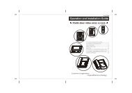
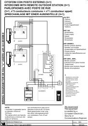
Nice Robus Kit 1 - Rolling Center
Nice Robus Kit 1 - Rolling Center
Nice Robus Kit 1 - Rolling Center

Create successful ePaper yourself
Turn your PDF publications into a flip-book with our unique Google optimized e-Paper software.
7.2.5) Level one programming example (ON-OFF functions).<br />
The sequence to follow in order to change the factory settings of the functions for activating “Automatic Closing” (L1) and “Always close” (L3)<br />
have been included as examples.<br />
Tabella 11: Level one programming example<br />
Example<br />
1. Press the key [Set] and hold it down (approx. 3 s)<br />
SET<br />
3s<br />
2. Release the [Set] key when L1 LED starts flashing<br />
L1 SET<br />
3. Press the [Set] key once to change the state of the function associated with L1<br />
Automatic Closing). LED L1 will now flash with long flashes.<br />
SET<br />
L1<br />
4. Press the [▼] key twice to move the flashing LED to LED L3<br />
L3<br />
5. Press the [Set] key once to change the state of the function associated with L3<br />
(Always Close). LED L3 will now flash with long flashes.<br />
SET L3<br />
6. Wait 10 seconds before leaving the programme to allow the maximum time to lapse.<br />
10s<br />
Once these operations have been completed, LEDs L1 and L3 must remain on to indicate that the “Automatic Closing” and the “Always<br />
Close” functions are active.<br />
7.2.6) Level two programming example (adjustable parameters)<br />
The sequence to follow in order to change the factory settings of the parameters increasing the “Pause Time” to 60 seconds (input on L1<br />
and level on L5) and reducing the “Motor Force” for light gates (input on L5 and level on L2) have been included as examples<br />
Table 12: Level two programming example<br />
1. Press the key [Set] and hold it down (approx. 3 s)<br />
2. Release the [Set] key when L1 LED starts flashing<br />
3. Press the key [Set] and hold it down during step 4 and 5<br />
4. Wait approx. 3 seconds until LED L3, representing the current level<br />
of the “Pause Time” will light up L3 3s<br />
5. Press the [▼] key twice to move the LED which is lit to LED L5,<br />
which represents the new “Pause Time” value<br />
L5<br />
6. Release the key [Set]<br />
7. Press the [▼] key four times to move the flashing LED to LED L5<br />
8. Press the key [Set]; and hold it down during step 9 and 10<br />
9. Wait approx. 3 seconds until LED L5, representing the current<br />
level of the “Motor Force” will light up 3s L5<br />
10. Press the [▲] key three times to move the LED which is lit to LED L2,<br />
which represents the new “Motor Force” value<br />
L2<br />
11. Release the key [Set]<br />
12. Wait 10 seconds before leaving the programme to allow the maximum time to lapse.<br />
Example<br />
SET<br />
L1<br />
SET<br />
SET<br />
SET<br />
SET<br />
SET<br />
3s<br />
10s<br />
L5<br />
7.3) Adding or removing devices<br />
Devices can be added to or removed from the ROBUS automation<br />
system at any time. In particular, various devices types can be connected<br />
to “BlueBUS” and “STOP” input as explained in the following<br />
paragraphs.<br />
After you have added or removed any devices, the<br />
automation system must go through the recognition<br />
process again according to the directions contained in<br />
paragraph 7.3.6 “Recognition of other devices”.<br />
7.3.1) BlueBUS<br />
BlueBUS technology allows you to connect compatible devices<br />
using only two wires which carry both the power supply and the<br />
communication signals. All the devices are connected in parallel on<br />
the 2 wires of the BlueBUS itself. It is not necessary to observe any<br />
polarity; each device is individually recognized because a univocal<br />
address is assigned to it during the installation. Photocells, safety<br />
devices, control keys, signalling lights etc. can be connected to<br />
BlueBUS. The ROBUS control unit recognizes all the connected<br />
devices individually through a suitable recognition process, and can<br />
detect all the possible abnormalities with absolute precision. For this<br />
reason, each time a device connected to BlueBUS is added or<br />
removed the control unit must go through the recognition process;<br />
see paragraph 7.3.6 “Recognition of Other Devices”.<br />
16