Nice Robus Kit 1 - Rolling Center
Nice Robus Kit 1 - Rolling Center
Nice Robus Kit 1 - Rolling Center

Create successful ePaper yourself
Turn your PDF publications into a flip-book with our unique Google optimized e-Paper software.
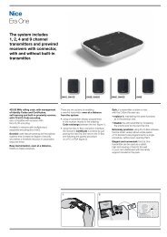
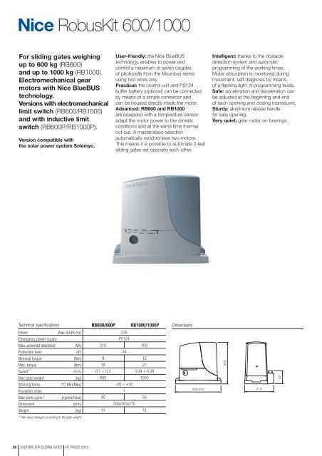
<strong>Robus</strong><strong>Kit</strong> 600/1000<br />
For sliding gates weighing<br />
up to 600 kg (RB600)<br />
and up to 1000 kg (RB1000).<br />
Electromechanical gear<br />
motors with <strong>Nice</strong> BlueBUS<br />
technology.<br />
Versions with electromechanical<br />
limit switch (RB600/RB1000)<br />
and with inductive limit<br />
switch (RB600P/RB1000P).<br />
Version compatible with<br />
the solar power system Solemyo.<br />
User-friendly: the <strong>Nice</strong> BlueBUS<br />
technology, enables to power and<br />
control a maximum of seven couples<br />
of photocells from the Moonbus series<br />
using two wires only.<br />
Practical: the control unit and PS124<br />
buffer battery (optional) can be connected<br />
by means of a simple connector and<br />
can be housed directly inside the motor.<br />
Advanced: RB600 and RB1000<br />
are equipped with a temperature sensor:<br />
adapt the motor power to the climatic<br />
conditions and at the same time thermal<br />
cut-out. A master/slave selection<br />
automatically synchronises two motors.<br />
This means it is possible to automate 2-leaf<br />
sliding gates set opposite each other.<br />
Intelligent: thanks to the obstacle<br />
detection system and automatic<br />
programming of the working times.<br />
Motor absorption is monitored during<br />
movement, self-diagnosis by means<br />
of a flashing light. 8 programming levels.<br />
Safe: acceleration and deceleration can<br />
be adjusted at the beginning and end<br />
of each opening and closing manoeuvre.<br />
Sturdy: aluminium release handle<br />
for easy opening.<br />
Very quiet: gear motor on bearings.<br />
Technical specifications<br />
RB600/600P<br />
RB1000/1000P<br />
Dimensions<br />
Power<br />
(Vac 50/60 Hz)<br />
Emergency power supply<br />
Max. powered absorbed (VA)<br />
Protection level<br />
(IP)<br />
Nominal torque<br />
(Nm)<br />
Max. torque<br />
(Nm)<br />
Speed*<br />
(m/s)<br />
Max gate weight<br />
(kg)<br />
Working temp. (°C Min/Max)<br />
Insulation class<br />
Max work cycle * (cycles/hour)<br />
Dimension<br />
(mm)<br />
Weight<br />
(kg)<br />
230<br />
PS124<br />
515 450<br />
44<br />
9 15<br />
18 27<br />
0.1 ÷ 0.3 0.09 ÷ 0.28<br />
600 1000<br />
-20 ÷ +50<br />
1<br />
40 50<br />
330x303x210<br />
11 13<br />
330 mm<br />
303<br />
210<br />
92<br />
* This value changes according to the gate weight.<br />
26 SYSTEMS FOR SLIDING GATES KIT PRICES 2010
<strong>Robus</strong><strong>Kit</strong><br />
For sliding gates weighing up to 600 kg<br />
<strong>Robus</strong><strong>Kit</strong> 1<br />
With BlueBUS technology, including:<br />
<strong>Nice</strong> Price<br />
£ 704.00<br />
ROBUS600<br />
irreversible<br />
electromechanical<br />
gear motor, with<br />
incorporated control unit,<br />
with electromechanical<br />
limit switch,<br />
for gates up to 600 kg<br />
1 pc<br />
ON2<br />
two transmitters<br />
433.92 MHz,<br />
2 channels<br />
2 pcs<br />
MOFB<br />
one couple of outdoor<br />
photocells designed<br />
for connection<br />
via <strong>Nice</strong> BlueBUS<br />
1 pc<br />
OXI<br />
receiver up to 4 channels<br />
with connector, without<br />
built-in transmitter<br />
1 pc
For sliding gates<br />
<strong>Robus</strong> 600/600P<br />
1000/1000P<br />
Instructions and warnings for the fitter<br />
Istruzioni ed avvertenze per l’installatore<br />
Instructions et recommandations pour l’installateur<br />
Anweisungen und Hinweise für den Installateur<br />
Instrucciones y advertencias para el instalador<br />
Instrukcje i uwagi dla instalatora<br />
Aanwijzingen en aanbevelingen voor de installateur
<strong>Robus</strong> 600/600P<br />
1000/1000P<br />
Table of contents:<br />
page<br />
1 Warnings 3<br />
2 Product description and applications 4<br />
2.1 Operating limits 4<br />
2.2 Typical system 6<br />
2.3 List of cables 6<br />
3 Installation 7<br />
3.1 Preliminary checks 7<br />
3.2 Installation of the gearmotor 7<br />
3.3 Fixing of the limit switch bracket<br />
on versions with inductive limit switch 8<br />
3.4 Installation of the various devices 9<br />
3.5 Electrical connections 9<br />
3.6 Description of the electrical connections 10<br />
4 Final checks and start up 10<br />
4.1 Choosing the direction 10<br />
4.2 Power supply connection 10<br />
4.3 Recognition of the devices 10<br />
4.4 Recognizing the length of the leaf 11<br />
4.5 Checking gate movements 11<br />
4.6 Preset functions 11<br />
4.7 Radio receiver 11<br />
5 Testing and commissioning 11<br />
5.1 Testing 12<br />
5.2 Commissioning 12<br />
6 Maintenance and Disposal 12<br />
6.1 Maintenance 12<br />
6.2 Disposal 12<br />
7 Additional information 13<br />
7.1 Programming keys 13<br />
7.2 Programming 13<br />
7.2.1 Level one functions (ON-OFF functions) 13<br />
7.2.2 Level one programming<br />
(ON-OFF functions) 14<br />
7.2.3 Level two functions<br />
(adjustable parameters) 14<br />
7.2.4 Level two programming<br />
(adjustable parameters) 15<br />
7.2.5 Level one programming example<br />
(ON-OFF functions) 16<br />
7.2.6 Level two programming example<br />
(adjustable parameters) 16<br />
7.3 Adding or removing devices 16<br />
7.3.1 BlueBUS 16<br />
7.3.2 STOP input 17<br />
7.3.3 Photocells 17<br />
7.3.4 FT210B Photo-sensor 17<br />
7.3.5 ROBUS in “Slave” mode 18<br />
7.3.6 Recognition of Other Devices 19<br />
7.4 Special functions 19<br />
7.4.1 “Always open” Function 19<br />
7.4.2 “Move anyway” function 19<br />
7.4.3 Maintenance warning 19<br />
7.5 Connection of Other Devices 20<br />
7.6 Troubleshooting 21<br />
7.6.1 Malfunctions archive 21<br />
7.7 Diagnostics and signals 21<br />
7.7.1 Flashing light signalling 22<br />
7.7.2 Signals on the control unit 22<br />
7.8 Accessories 23<br />
8 Technical characteristics 24<br />
Instructions and Warnings for users of<br />
ROBUS gearmotor 25<br />
2
1) Warnings<br />
This manual contains important information regarding safety. Before you<br />
start installing the components, it is important that you read all the information<br />
contained herein. Store this manual safely for future use.<br />
Due to the dangers which may arise during both the installation and use<br />
of the ROBUS, installation must be carried out in full respect of the laws,<br />
provisions and rules currently in force in order to ensure maximum safety.<br />
This chapter provides details of general warnings. Other, more specific<br />
warnings are detailed in Chapters “3.1 Preliminary Checks” and “5<br />
Testing and Commissioning”.<br />
! According to the most recent European legislation, the<br />
automation of doors or gates is governed by the provisions<br />
listed in Directive 98/37/CE (Machine Directive) and, more<br />
specifically, to provisions: EN 13241-1 (harmonised standard);<br />
EN 12445; EN 12453 and EN 12635, which enables to declare<br />
the conformity to the machine directive.<br />
Please access “www.niceforyou.com” for further information, and guidelines<br />
for risk analysis and how to draw up the Technical Documentation.<br />
This manual has been especially written for use by qualified fitters.<br />
Except for the enclosed specification “Instructions and Warnings for<br />
Users of the ROBUS gearmotor” which is to be removed by the installer,<br />
none of the information provided in this manual can be considered as<br />
being of interest to end users!<br />
• Any use or operation of ROAD200 which is not explicitly provided for<br />
in these instructions is not permitted. Improper use may cause damage<br />
and personal injury.<br />
• Risk analysis must be carried out before starting installation, to include<br />
the list of essential safety requisites provided for in Enclosure I of the<br />
Machine Directive, indicating the relative solutions employed.<br />
Risk analysis is one of the documents included in the “Technical Documentation”<br />
for this automation.<br />
• Check whether additional devices are needed to complete the<br />
automation with ROBUS based on the specific application requirements<br />
and dangers present. The following risks must be considered:<br />
impact, crushing, shearing, dragging, etc. as well as other general<br />
dangers.<br />
• Do not modify any components unless such action is specified in this<br />
manual. Operations of this type are likely to lead to malfunctions. NICE<br />
disclaims any liability for damage resulting from modified products.<br />
• During installation and use, ensure that solid objects or liquids do not<br />
penetrate inside the control unit or other open devices. If necessary,<br />
please contact the NICE customer service department; the use of<br />
ROBUS in these conditions can be dangerous.<br />
• The automation system must not be used until it has been commissioned<br />
as described in chapter 5 “Testing and commissioning”.<br />
• The ROBUS packing materials must be disposed of in compliance<br />
with local regulations.<br />
• If a fault occurs that cannot be solved using the information provided<br />
in this manual, refer to the NICE customer service department.<br />
• In the event that any automatic switches are tripped or fuses blown,<br />
you must identify the fault and eliminate it.<br />
• Disconnect all the power supply circuits before accessing the terminals<br />
inside the ROBUS cover. If the disconnection device is not identifiable,<br />
post the following sign on it: “WARNING: MAINTENANCE WORK IN<br />
PROGRESS”.<br />
Particular warnings concerning the suitable use of this product in relation<br />
to the 98/37CE “Machine Directive” (ex 89/392/EEC):<br />
• This product comes onto the market as a “machine component” and<br />
is therefore manufactured to be integrated to a machine or assembled<br />
with other machines in order to create “a machine”, under the directive<br />
98/37/EC, only in combination with other components and in the manner<br />
described in the present instructions manual. As specified in the<br />
directive 98/37CE the use of this product is not admitted until the manufacturer<br />
of the machine on which this product is mounted has identified<br />
and declared it as conforming to the directive 98/37/CE.<br />
Particular warnings concerning the suitable use of this product in relation<br />
to the 73/23/EEC “Low Voltage” Directive and subsequent modification<br />
93/68/EEC:<br />
• This product responds to the provisions foreseen by the “Low Voltage”<br />
Directive if used in the configurations foreseen in this instructions manual<br />
and in combination with the articles present in the <strong>Nice</strong> S.p.a. product<br />
catalogue. If the product is not used in configurations or is used<br />
with other products that have not been foreseen, the requirements<br />
may not be guaranteed; the use of the product is prohibited in these<br />
situation until the correspondence with the requirements foreseen by<br />
the directive have been verified by installers.<br />
Particular warnings concerning the suitable use of this product in relation<br />
to the 89/336/EEC “Electromagnetic Compatibility” Directive and subsequent<br />
modifications 92/31/EEC and 93/68/EEC:<br />
• This product has been subjected to tests regarding the electromagnetic<br />
compatibility in the most critical of use conditions, in the configurations<br />
foreseen in this instructions manual and in combination with<br />
articles present in the <strong>Nice</strong> S.p.A. product catalogue. The electromagnetic<br />
compatibility may not be guaranteed if used in configurations or<br />
with other products that have not been foreseen the use of the product<br />
is prohibited in these situations until the correspondence to the<br />
requirements foreseen by the directive have been verified by those performing<br />
the installation.<br />
GB<br />
3
2) Product description and applications<br />
ROBUS is a line of irreversible electromechanical gearmotors for the<br />
automation of sliding gates. It is equipped with an electronic control<br />
unit and connector for the optional SMXI or SMXIS radiocontrol<br />
receiver. The electrical connections to external devices have been<br />
simplified through the use of “BlueBUS”, a technique by which several<br />
devices can be connected up using just 2 wires. ROBUS operates<br />
with electric power. In the event of a power failure, the gearmotor<br />
can be released using a special key in order to move the gate<br />
manually. Alternatively, there is the PS124 buffer battery (optional<br />
accessory) which makes it possible to use the gate also during the<br />
event of a power failure.<br />
Other products are also part of the ROBUS line, the difference of which is described in table 1.<br />
Table 1: comparison of the ROBUS gearmotor main characteristics<br />
Gearmotor type RB600 RB600P RB1000 RB1000P<br />
Limit switch type electromechanical inductive proximity electromechanical inductive proximity<br />
Maximum leaf length 8m 12m<br />
Maximum leaf weight 600Kg 1000Kg<br />
Peak thrust 18Nm 27Nm<br />
corresponding to a force) (600N) (900N)<br />
Motor and transformer Motor 24Vcc Ø 77mm Motor 24Vcc Ø 115mm<br />
EI core-type transformer<br />
Toroidal transformer<br />
Note: 1Kg = 9,81N for example: 600N = 61Kg<br />
92mm<br />
303mm<br />
1<br />
330mm<br />
210mm<br />
2.1) Operating limits<br />
Chapter 8 “Technical Characteristics” provides the only data needed<br />
to determine whether the products of the ROBUS line are suitable for<br />
the intended application.<br />
The structural characteristics of ROBUS make it suitable for use on sliding<br />
leaves in conformity with the limits indicated in tables 2, 3 and 4.<br />
data indicated in tables 2 and 3 to establish the number of<br />
cycles/hour, consecutive cycles and maximum speed allowed.<br />
The effective suitability of ROBUS to automate a particular sliding<br />
gate depends on the friction as well as other correlated factors, such<br />
as ice, that could interfere with the movement of the leaf.<br />
For an effective control it is absolutely vital to measure the force necessary<br />
to move the leaf throughout its entire run and ensure that this<br />
is less than half of the “nominal torque” indicated in chapter 8 “Technical<br />
characteristics” (a 50% margin on the force is recommended,<br />
as unfavourable climatic conditions may cause an increase in the<br />
friction); furthermore, it is necessary to take into consideration the<br />
Table 2: limits in relation to the length of the leaf<br />
RB600, RB600P<br />
RB1000, RB1000P<br />
Leave width (m) max. cycle/hour max. no. of consecutive cycles max. cycle/hour max. no. of consecutive cycles<br />
Up to 4 40 20 50 25<br />
4 ÷ 6 25 13 33 16<br />
6 ÷ 8 20 10 25 12<br />
8 ÷ 10 --- --- 20 10<br />
10 ÷ 12 --- --- 16 8<br />
4
Table 3: limits in relation to the weight of the leaf<br />
RB600, RB600P<br />
RB1000, RB1000P<br />
Leaf weight (kg) % cycles Maximum speed % cycles Maximum speed<br />
allowed<br />
allowed<br />
Up to 200 100% V6 = Extremely fast 100% V6 = Extremely fast<br />
200 ÷ 400 80 V5 = Very fast 90 V5 = Very fast<br />
400 ÷ 500 60 V4 = Fast 75 V4 = Fast<br />
500 ÷ 600 50 V3 = Medium 60 V4 = Fast<br />
600 ÷ 800 --- --- 50 V3 = Medium<br />
800 ÷ 900 --- --- 45 V3 = Medium<br />
900 ÷ 1000 --- --- 40 V3 = Medium<br />
GB<br />
The length of the leaf makes it possible to determine both the maximum number of cycles per hour and consecutive cycles, while the weight<br />
makes it possible to determine the reduction percentage of the cycles and the maximum speed allowed. For example, for ROBUS 1000 if<br />
the leaf is 5 m long it will be possible to have 33 cycles/hour and 16 consecutive cycles. However, if the leaf weighs 700 Kg, they must be<br />
reduced to 50%, resulting in 16 cycles/hour and 8 consecutive cycles, while the maximum speed allowed is V4: fast. The control unit has a<br />
limiting device which prevents the risk of overheating based on the load of the motor and duration of the cycles. This device triggers when<br />
the maximum limit is exceeded. The manoeuvre limiting device also measures the ambient temperature reducing the manoeuvre further when<br />
the temperature is particularly high.<br />
The “durability” estimate is shown in chapter 8 “Technical characteristics”, which is the average useful life of the product. The value is deeply<br />
influenced by the severity index of the manoeuvre, this being the sum of all factors that contribute to wear. To perform this estimate, all severity<br />
indexes in table 4 must be totalled, then the estimated durability in the graph must be checked with the total result.<br />
For example, when ROBUS 1000 is fitted to a gate weighing 650 Kg and 5m in length, equipped with photocells and without other stress<br />
related elements, it obtains a severity index equal to 50% (30+10+10). From the graph the estimated durability is equal to 80,000 cycles.<br />
Table 4: durability estimate in relation to the manoeuvre severity index<br />
Severity index % <strong>Robus</strong> Durability in cycles<br />
600 1000<br />
Leaf weight Kg<br />
Up to 200 10 5<br />
200 ÷ 400 30 10<br />
400 ÷ 600 50 20<br />
600 ÷ 700 --- 30<br />
700 ÷ 800 --- 40<br />
800 ÷ 900 --- 50<br />
900 ÷ 1000 --- 60<br />
Leaf length m<br />
Up to 4 10 5<br />
4 ÷ 6 20 10<br />
6 ÷ 8 35 20<br />
8 ÷ 10 --- 35<br />
10 ÷ 12 --- 50<br />
Other stress related elements<br />
(to be taken into consideration if the probability that<br />
they occur is greater than 10% )<br />
Surrounding temperature greater than 40°C<br />
or lower than 0°C or humidity greater than 80%<br />
10 10<br />
Presence of dust and sand 15 15<br />
Presence of salinity 20 20<br />
Photo manoeuvre interruption 15 10<br />
Stop manoeuvre interruption 25 20<br />
Speed greater than “L4 fast” 20 15<br />
Thrust active 25 20<br />
Severity index total%:<br />
Durability in cycles<br />
Severity index %<br />
Note: if the severity index exceeds 100%, this means that the conditions are beyond the acceptable limits; a larger model is therefore advised.<br />
5
2.2) Typical system<br />
Figure 2 shows a typical system for automating a sliding gate using ROBUS<br />
1<br />
4 3 5<br />
3 8<br />
9<br />
12<br />
6<br />
7<br />
2<br />
11<br />
13<br />
10<br />
F<br />
B<br />
A<br />
D<br />
2<br />
E C F<br />
C<br />
2<br />
1 Key-operated selector switch<br />
2 Photocells on post<br />
3 Photocells<br />
4 Main fixed edge (optional)<br />
5 Main movable edge<br />
6 “Open” stop bracket<br />
7 Rack<br />
8 Secondary fixed edge (optional)<br />
9 Flashing light with incorporated aerial<br />
10 ROBUS<br />
11 “Closed” stop bracket<br />
12 Secondary movable edge (optional)<br />
13 Radio-transmitter<br />
2.3) List of cables<br />
Figure 2 shows the cables needed for the connection of the devices in a typical installation; table 5 shows the cable characteristics.<br />
! The cables used must be suitable for the type of installation; for example, an H03VV-F type cable is recommended for indoor<br />
applications, while H07RN-F is suitable for outdoor applications.<br />
Table 5: List of cables<br />
Connection Cable type Maximum length allowed<br />
A: Power line 1 3x1,5mm 2 cable 30m (note 1)<br />
B: Flashing light with aerial 1 2x0,5mm 2 cable 20m<br />
1 RG58 type shielded cable 20m (recommended less than 5 m)<br />
C: Photocells 1 2x0,5mm 2 cable 30m (note 2)<br />
D: Key-operated selector switch 2 2x0,5mm 2 cable (note 3) 50m<br />
E: Fixed edges 1 2x0,5mm 2 cable (note 4) 30m<br />
F: Movable edges 1 2x0,5mm 2 cable (note 4) 30m (note 5)<br />
Note 1:<br />
Note 2:<br />
Note 3:<br />
Note 4:<br />
Note 5:<br />
power supply cable longer than 30 m may be used provided it has a larger gauge, e.g. 3x2,5mm 2 , and that a safety grounding system<br />
is provided near the automation unit.<br />
If the “BLUEBUS” cable is longer than 30 m, up to 50 m, a 2x1mm 2 cable is needed.<br />
A single 2x0,5mm 2 cable can be used instead of two 4x0,5mm 2 cables.<br />
Please refer to Chapter “7.3.2 STOP Input” in situations where there is more than one edge, for information about the type of connection<br />
recommended by the manufacturer.<br />
special devices which enable connection even when the leaf is moving must be used to connect movable edges to sliding leaves.<br />
6
3) Installation<br />
! The installation of ROBUS must be carried out by qualified personnel in compliance with current legislation, standards and<br />
regulations, and the directions provided in this manual.<br />
GB<br />
3.1) Preliminary checks<br />
Before proceeding with the installation of ROBUS you must:<br />
•Check that all the materials are in excellent condition, suitable for<br />
use and that they conform to the standards currently in force.<br />
• Make sure that the structure of the gate is suitable for automation.<br />
• Make sure that the weight and dimensions of the leaf fall within the<br />
specified operating limits provided in chapter “2.1 Operating limits”.<br />
• Check that the force required to start the movement of the leaf is<br />
less than half the “maximum torque”, and that the force required to<br />
keep the leaf in movement is less than half the “nominal torque”.<br />
Compare the resulting values with those specified in Chapter “8<br />
Technical Characteristics”. The manufacturers recommend a 50%<br />
margin on the force, as unfavourable climatic conditions may<br />
cause an increase in the friction.<br />
• Make sure that there are no points of greater friction in the opening<br />
or closing travel of the gate leaves.<br />
• Make sure there is no danger of the gate derailing.<br />
• Make sure that the mechanical stops are sturdy enough and that<br />
there is no risk of the deformation even when the leaf hits the<br />
mechanical stop violently.<br />
• Make sure that the gate is well balanced: it must not move by itself<br />
when it is placed in any position.<br />
•Make sure that the area where the gearmotor is fixed is not subject<br />
to flooding. If necessary, mount the gearmotor raised from the<br />
ground.<br />
• Make sure that the installation area enables the release of the gearmotor<br />
and that it is safe and easy to release it.<br />
• Make sure that the mounting positions of the various devices are<br />
protected from impacts and that the mounting surfaces are sufficiently<br />
sturdy.<br />
• Components must never be immersed in water or other liquids.<br />
• Keep ROBUS away from heat sources and open flames; in acid,<br />
saline or potentially explosive atmosphere; this could damage<br />
ROBUS and cause malfunctions or dangerous situations.<br />
• If there is an access door in the leaf, or within the range of movement<br />
of the gate, make sure that it does not obstruct normal travel.<br />
Mount a suitable interblock system if necessary.<br />
• Only connect the control unit to a power supply line equipped with<br />
a safety grounding system.<br />
• The power supply line must be protected by suitable magnetothermal<br />
and differential switches.<br />
• A disconnection device must be inserted in the power supply line<br />
from the electrical mains (the distance between the contacts must<br />
be at least 3.5 mm with an overvoltage category of III) or equivalent<br />
system, for example an outlet and relative plug. If the disconnection<br />
device for the power supply is not mounted near the<br />
automation, it must have a locking system to prevent unintentional,<br />
unauthorised connection.<br />
3.2) Installation of the gearmotor<br />
The gearmotor must be fastened directly to an already existing<br />
mounting surface using suitable means, for example expansion<br />
screw anchors. Otherwise, in order to fasten the gearmotor the<br />
installer must:<br />
1. Dig a foundation hole with suitable dimensions referring to Figure 3.<br />
2. Prepare one or more conduits for the electrical cables as shown<br />
in figure 4.<br />
3. Assemble the two clamps on the foundation plate setting one nut<br />
underneath and one on top of the plate. The nut underneath the<br />
plate must be as shown in Figure 5 screwed so that the threaded<br />
part protrudes above the plate by approximately 25÷35 mm.<br />
4. Pour the concrete and, before it starts to harden, set the foundation<br />
plate to the values shown in Figure 3. Check that it is parallel<br />
to the leaf and perfectly level (Figure 6). Wait for the concrete<br />
to harden completely.<br />
5. Remove the 2 upper nuts of the plate and then place the gearmotor<br />
onto them. Check that it is perfectly parallel to the leaf,<br />
then screw the two nuts and washers supplied, as shown in Figure<br />
7.<br />
0÷10<br />
25÷35<br />
192<br />
330 0÷50<br />
4<br />
5<br />
0÷10<br />
192<br />
3<br />
0÷50 330<br />
6<br />
7<br />
7
If the rack is already present, once the gearmotor has been fastened,<br />
use the adjustment dowels as shown in Figure 8 to set the pinion of<br />
ROBUS to the right height, leaving 1÷2 mm of play from the rack.<br />
Otherwise, in order to fasten the rack the installer must:<br />
6. Release the gearmotor as shown in “Release and manual movement”<br />
paragraph in the Chapter “Instructions and Warnings for<br />
users of the ROBUS gearmotor”.<br />
7. Open the leaf up completely and place the first piece of the rack<br />
on the pinion. Check that the beginning of the rack corresponds<br />
to the beginning of the leaf, as shown in Figure 9. Leave a 1÷2<br />
mm play between the rack and the pinion, then fasten the rack to<br />
the leaf using suitable means.<br />
1÷2<br />
8 9 10<br />
11 12<br />
! In order to prevent the weight of the leaf from affecting the<br />
gearmotor, it is important that there is a play of 1÷2 mm between<br />
the rack and the pinion as shown in Figure 10.<br />
8. Slide the leaf, using the pinion as a reference point for the fastening<br />
the other elements of the rack.<br />
9. Cut away the exceeding part of the rack.<br />
10. Open and close the gate several times and make sure that the rack<br />
is aligned with the pinion with a maximum tolerance of 5 mm. Moreover,<br />
check that the play of 1÷2 mm has been respected along the<br />
entire length between the pinion and the rack.<br />
11. Thoroughly tighten the two fixing nuts of the gearmotor making sure<br />
it is well fastened to the ground. Cover the fixing nuts with the relative<br />
caps as shown in figure 11.<br />
12. Fix the limit switch bracket as described below (for versions<br />
RB600P and RB1000P, fix the bracket as described in paragraph<br />
“3.3 Fixing of the limit switch bracket on versions with inductive limit<br />
switch”):<br />
• Manually place the leaf in the open position leaving at least 2-3 cm<br />
from the mechanical stop.<br />
• Slide the bracket along the rack in the opening direction until the<br />
limit switch cuts-in. Then bring the bracket forward by at least 2<br />
cm and secure it to the rack with the appropriate dowels, as in fig.<br />
12.<br />
• Perform the same operation for the closure limit switch.<br />
13. Lock the gearmotor as shown in “Release and manual movement”<br />
paragraph in the Chapter “Instructions and Warnings for Users”<br />
3.3) Fixing of the limit switch bracket on versions with inductive limit switch<br />
The limit switch bracket must be fixed as described below for the<br />
RB600P and RB1000P versions that utilise the inductive limit switch.<br />
1. Manually place the leaf in the open position leaving at least<br />
2-3 cm from the mechanical stop.<br />
2. Slide the bracket along the rack in the opening direction until the<br />
corresponding LED switches off, as in fig. 13. Then bring the<br />
bracket forward by at least 2 cm and secure it to the rack with the<br />
appropriate dowels.<br />
3. Manually place the leaf in the closed position leaving at least 2-3<br />
cm from the mechanical stop<br />
4. Slide the bracket along the rack in the closing direction until the<br />
corresponding LED switches off. Then bring the bracket forward<br />
by at least 2 cm and secure it to the rack with the appropriate<br />
dowels.<br />
! The ideal distance of the bracket for inductive limit switches<br />
is between 3 and 8 mm as indicated in fig. 14.<br />
13<br />
14<br />
3÷8<br />
8
3.4) Installation of the various devices<br />
If other devices are needed, install them following the directions provided in the corresponding instructions. Check this in paragraph “3.6<br />
Description of electrical connections” and the devices which can be connected to the ROBUS in Figure 2.<br />
GB<br />
3.5) Electrical connections<br />
! Only carry out electrical connections once the electricity<br />
supply to the system has been switched off. Disconnect<br />
any buffer batteries present.<br />
1. Remove the protection cover in order to access the electronic control unit of<br />
the ROBUS. The side screw must be removed, and the cover lifted upwards.<br />
2. Remove the rubber membrane which closes the hole for passage of the<br />
cables and insert all the connection cables towards the various devices,<br />
leaving a length of 20÷30 cm longer than necessary. See Table 5 for information<br />
regarding the type of cables and Figure 2 for the connections.<br />
3. Use a clamp to collect together and join the cables which enter the gearmotor.<br />
Place the clamp just underneath the hole the cables enter<br />
through.<br />
Make a hole in the rubber membrane which is slightly smaller than the<br />
diameter of the cables which have been collected together, and insert the<br />
membrane along the cables until you reach the clamp. Then put the<br />
membrane back in the slot of the hole the cables pass through. Lay a<br />
second clamp for collecting the cables which are set just above the<br />
membrane.<br />
4. Connect the power cable to the appropriate terminal as shown in figure<br />
15, then block the cable at the first cable block ring using the clamp.<br />
5. Connect up the other cables according to the diagram in Figure 17. The<br />
terminals can be removed in order to make this work easier.<br />
6. Once the connections have been completed, block the cables collected in the<br />
second cable block ring using clamps. The excess of the aerial cable must be<br />
blocked to the other cables using another clamp as shown in Figure 16.<br />
15<br />
16<br />
LUCYB S.C.A. MOFB OPEN CLOSE<br />
MOSE<br />
17<br />
See paragraph “7.3.5 ROBUS in Slave mode” for the connection of 2 motors on opposite leaves.<br />
9
3.6) Description of the electrical connections<br />
The following is a brief description of the electrical connections; for<br />
further information please read “7.3 Adding or Removing Devices”<br />
paragraph.<br />
FLASH: output for one or two “LUCYB” or similar type flashing<br />
lights with single 12V maximum 21W bulb.<br />
S.C.A.: “Open Gate Light” output. An indication lamp can be connected<br />
(24V max. 4W). It can also be programmed for other functions;<br />
see paragraph “7.2.3 Level two functions”.<br />
BLUEBUS: compatible devices can be connected up to this terminal.<br />
They are connected in parallel using two conductors only,<br />
through which both the electricity supply and the communication<br />
signals travel. For more useful information about BlueBUS see also<br />
Paragraph “7.3.1 BlueBUS”.<br />
STOP: input for the devices which block or eventually stop the<br />
manoeuvre in progress. Contacts like “Normally Closed”, “Normally<br />
Open” or constant resistance devices can be connected up using<br />
special procedures on the input. For more useful information about<br />
STOP see also Paragraph “7.3.2 STOP Input”.<br />
STEP-BY-STEP: input for devices which control Step-by-Step<br />
movement. It is possible to connect “Normally Open” devices up to<br />
this input.<br />
OPEN: input for devices which control only the opening movement.<br />
It is possible to connect “Normally Open” devices up to this<br />
input.<br />
CLOSE: input for devices which control only the closing movement.<br />
It is possible to connect “Normally Open” devices up to this<br />
input.<br />
AERIAL: connection input for the radio receiver aerial (the aerial is<br />
incorporated in LUCY B).<br />
4) Final checks and start up<br />
The manufacturers recommend you position the leaf at approximately half travel before starting the checking and start up phase of the<br />
automation. This will ensure the leaf is free to move both during opening and closure.<br />
4.1) Choosing the direction<br />
The direction of the opening manoeuvre must be chosen depending<br />
on the position of the gearmotor with respect to the leaf. If the leaf<br />
must move left for opening, the selector must be moved towards left<br />
as shown in Figure 18; alternatively, if the leaf has to move right during<br />
opening, the selector must be moved towards the right as shown<br />
in Figure 19<br />
18<br />
19<br />
4.2) Power supply connection<br />
! The connection of ROBUS to the mains must be made<br />
by qualified and experienced personnel in possession of<br />
the necessary requisites and in full respect of the laws,<br />
provisions and standards currently in force.<br />
As soon as ROBUS is energized, you should check the following:<br />
1. Make sure that the “BLUEBUS” LED flashes regularly, with about<br />
one flash per second.<br />
2. Make sure that the LED’s on the photocells flash (both on TX and<br />
RX); the type of flashing is not important as it depends on other<br />
factors.<br />
3. Make sure that the flashing light connected to the FLASH output<br />
and the lamp LED connected to the “Open Gate Indicator” output<br />
are off.<br />
If the above conditions are not satisfied, you should immediately<br />
switch off the power supply to the control unit and check the electrical<br />
connections more carefully.<br />
Please refer to Chapter “7.6 Troubleshooting” for further information<br />
about finding and analysing failures.<br />
4.3) Recognition of the devices<br />
After connecting up the power supply, the control unit must be made to recognise the devices connected up to the BLUEBUS and STOP<br />
inputs. Before this phase, LEDs L1 and L2 will flash to indicate that recognition of the devices must be carried out.<br />
1. Press keys [▲] and [Set] and hold them down<br />
2. Release the keys when L1 and L2 LED’s start flashing very quickly (after approx. 3 s)<br />
3. Wait a few seconds for the control unit to finish recognizing the devices<br />
4. When the recognition stage is completed the STOP LED must remain on while the<br />
L1 and L2 LED’s must go off (LEDs L3 and L4 will eventually start flashing).<br />
20<br />
The connected devices recognition stage can be repeated at any time, even after the installation (for example, if a device is installed); for performing<br />
the new recognition see paragraph “7.3.6 Recognition of Other Devices”.<br />
10
4.4) Recognizing the length of the leaf<br />
After recognizing the devices, L3 and L4 LED’s start flashing; the control unit must recognize the length of the gate. During this stage, the<br />
length of the leaf is measured from the closing limit switch to the opening limit switch. This measurement is required to calculate the deceleration<br />
points and the partial opening point.<br />
GB<br />
1. Press keys [▼] and [Set] and hold them down<br />
2. Release the keys when the manoeuvre starts (after approx. 3 s)<br />
3. Check the manoeuvre in progress is an opening manoeuvre. Otherwise, press the [Stop] key and<br />
carefully check Paragraph “4.1 Choosing the Direction”, then repeat the process from Point 1.<br />
4. Wait for the control unit to open the gate until it reaches the opening limit switch; the closing manoeuvre will<br />
start immediately afterwards.<br />
5. Wait for the control unit to close the gate.<br />
21<br />
If the above conditions are not satisfied, you should immediately switch off the power supply to the control unit and check the electrical connections<br />
more carefully. For more useful information see also chapter “7.6 Troubleshooting”.<br />
4.5) Checking gate movements<br />
On completion of the recognition of the length of the leaf, it is advisable<br />
to carry out a number of manoeuvres in order to check the gate<br />
travels properly.<br />
1. Press the [Open] key to open the gate. Check that gate opening<br />
occurs regularly, without any variations in speed. The leaf must<br />
only slowdown and stop when it is between 70 and 50 cm from<br />
the opening mechanical stop. Then, at 2÷3 cm from the mechanical<br />
opening stop the limit switch will trigger.<br />
2. Press the [Close] key to close the gate. Check that gate closing<br />
occurs regularly, without any variations in speed. The leaf must<br />
only slowdown and stop when it is between 70 and 50 cm from<br />
the closing mechanical stop. Then, at 2÷3 cm from the mechanical<br />
closing stop the limit switch will trigger.<br />
3. During the manoeuvre, check that the flashing light flashes at a<br />
speed of 0.5 seconds on and 0.5 seconds off. If present, also<br />
check the flashes of the light connected to the S.C.A. terminal:<br />
slow flashes during opening, quick flashes during closing.<br />
4.Open and close the gate several times to make sure that there are<br />
no points of excessive friction and that there are no defects in the<br />
assembly or adjustments.<br />
5. Check that the fastening of the ROBUS gearmotor, the rack and<br />
the limit switch brackets are solid, stable and suitably resistant,<br />
even if the gate accelerates or decelerates sharply.<br />
4.6) Preset functions<br />
The ROBUS control unit has a number of programmable functions.<br />
These functions are set to a configuration which should satisfy most<br />
automations. However, the functions can be altered at any time by<br />
means of a special programming procedure.<br />
Please refer to paragraph “7.2 Programming” for further information<br />
about this.<br />
4.7) Radio receiver<br />
The “SM” radio receiver connector for SMXI or SMXIS type optional radio receivers has been provided in order to enable the user to control<br />
ROBUS from a distance. For further information consult the radio receiver instructions manual. The association between the radio receiver<br />
output and the command performed by ROBUS is described in table 6:<br />
Table 6: commands with transmitter<br />
Output N°1<br />
Output N°2<br />
Output N°3<br />
Output N°4<br />
STEP-BY-STEP command<br />
“Partial opening” command<br />
“Open” command<br />
“Close” command<br />
22<br />
5) Testing and commissioning<br />
This is the most important stage in the automation system installation<br />
procedure in order to ensure the maximum safety levels. Testing<br />
can also be adopted as a method of periodically checking that all the<br />
various devices in the system are functioning correctly.<br />
! Testing of the entire system must be performed by<br />
qualified and experienced personnel who must establish<br />
which tests to conduct on the basis of the risks involved,<br />
and verify the compliance of the system with applicable<br />
regulations, legislation and standards, in particular with<br />
all the provisions of EN standard 12445 which establishes<br />
the test methods for automation systems for gates.<br />
11
5.1) Testing<br />
Each component of the system, e.g. safety edges, photocells, emergency<br />
stop, etc. requires a specific testing phase. We therefore recommend<br />
observing the procedures shown in the relative instruction<br />
manuals. To test ROBUS proceed as follows:<br />
1. Ensure that the instructions outlined in this manual and in particular<br />
in chapter 1 "WARNINGS" have been observed in full;<br />
2. Release the gearmotor as shown in “Release and manual movement”<br />
paragraph in chapter “Instructions and Warnings for users<br />
of the ROBUS gearmotor”<br />
3. Make sure you can move the door manually both during opening<br />
and closing with a force of max. 390N (40 kg approx.).<br />
4. Lock the gearmotor.<br />
5. Using the control or stop devices (key-operated selector switch,<br />
control buttons or radio transmitter) test the opening, closing and<br />
stopping of the gate and make sure that the leaves move in the<br />
intended direction.<br />
6. Check the proper operation of all the safety devices, one by one<br />
(photocells, sensitive edges, emergency stop, etc.) and check<br />
that the gate performs as it should. In particular, each time a<br />
device is activated the “BlueBUS” LED on the control unit flashes<br />
2 times quickly, confirming that the control unit recognizes the<br />
event.<br />
7. If the dangerous situations caused by the movement of the leaf<br />
have been safeguarded by limiting the force of impact, the user<br />
must measure the impact force according to EN Standard 12445.<br />
If the adjustment of the “speed” and control of the “motor force”<br />
are used to assist the system for the reduction of the impact<br />
force, try to find the adjustment that gives the best results.<br />
5.2) Commissioning<br />
Commissioning can take place only after all the testing phases of the<br />
ROBUS and the other devices have been terminated successfully. It<br />
is not permissible to execute partial commissioning or to enable use<br />
of the system in makeshift conditions.<br />
1. Prepare and store for at least 10 years the technical documentation<br />
for the automation, which must include at least: assembly drawing<br />
of the automation, wiring diagram, analysis of hazards and solutions<br />
adopted, manufacturer’s declaration of conformity of all the devices<br />
installed (for ROBUS use the annexed CE declaration of conformity);<br />
copy of the instruction manual and maintenance schedule of the<br />
automation.<br />
2. Post a label on the gate providing at least the following data: type<br />
of automation, name and address of manufacturer (person<br />
responsible for the “commissioning”), serial number, year of manufacture<br />
and “CE” marking.<br />
3. Post a permanent label or sign near the gate detailing the operations<br />
for the release and manual manoeuvre.<br />
4. Prepare the declaration of conformity of the automation system<br />
and deliver it to the owner.<br />
5. Prepare the “Instructions and warnings for the use of the automation<br />
system” and deliver it to the owner.<br />
6. Prepare the maintenance schedule of the automation system and<br />
deliver it to the owner; it must provide all directions regarding the<br />
maintenance of the single automation devices.<br />
7. Before commissioning the automation system inform the owner in<br />
writing regarding dangers and hazards that are still existing (e.g.<br />
in the “Instructions and warnings for the use of the automation<br />
system”).<br />
6) Maintenance and Disposal<br />
This charter provides information about how to draw up a maintenance schedule, and the disposal of ROBUS<br />
6.1) Maintenance<br />
The automation must be subjected to maintenance work on a regular<br />
basis, in order to guarantee it lasts; to this end ROBUS has a<br />
manoeuvre counter and maintenance warning system; see paragraph<br />
“7.4.3 Maintenance warning”<br />
! The maintenance operations must be performed in<br />
strict compliance with the safety directions provided in<br />
this manual and according to the applicable legislation<br />
and standards.<br />
If other devices are present, follow the directions provided in the corresponding<br />
maintenance schedule.<br />
1. ROBUS requires scheduled maintenance work every 6 months or<br />
20,000 manoeuvres (max.) after previous maintenance:<br />
2. Disconnect the power supply (and buffer batteries, if featured)<br />
3. Check for any deterioration of the components which form the<br />
automation, paying particular attention to erosion or oxidation of<br />
the structural parts. Replace any parts which are below the<br />
required standard.<br />
4. Check the wear and tear on the moving parts: pinion, rack and<br />
the leaf components; if necessary replace them.<br />
5. Connect the electric power sources up again, and carry out the<br />
testing and checks provided for in Paragraph “5.1 Testing”.<br />
6.2) Disposal<br />
ROBUS is constructed of various types of materials, some of which<br />
can be recycled: steel, aluminium, plastic, electric cables; while others<br />
must be disposed of (batteries and electronic boards).<br />
! Some electronic components and the batteries may<br />
contain polluting substances; do not pollute the environment.<br />
Enquire about the recycling or disposal systems<br />
available in compliance regulations locally in force.<br />
1. Disconnect the power supply of the automation system (and the buffer<br />
battery, if featured).<br />
2. Disassemble all the devices and accessories, following in reverse order<br />
the procedures described in chapter 3 “Installation”.<br />
3. Wherever possible, separate any parts which can or must be recycled<br />
or disposed of in different ways, e.g. metal parts must be disposed of<br />
separately from plastic ones, as must the electronic cards, batteries etc.<br />
4. Sort the various materials and consign them to local licensed firms for<br />
recovery and disposal.<br />
12
7) Additional information<br />
Programming, personalisation and how to look for and deal with faults on the ROBUS will be dealt with in this chapter.<br />
GB<br />
7.1) Programming keys<br />
The ROBUS control unit feature three keys that can be used to command<br />
the control unit both during tests and programming.<br />
Open<br />
▲<br />
Stop<br />
Set<br />
Close<br />
▼<br />
The “OPEN” key enables the user to control the opening<br />
of the gate or move the programming point upwards.<br />
The “STOP” key enables the user to stop the manoeuvre. If pressed down<br />
for more than 5 seconds it enables the user to enter programming.<br />
The “CLOSE” key enables the user to control the closing of the gate or<br />
move the programming point downwards.<br />
23<br />
7.2) Programming<br />
A number of programmable functions are available on the ROBUS<br />
control unit. The functions are adjusted using 3 keys set on the control<br />
unit: [▲] [Set] [▼] and are used by means of 8 LEDs: L1….L8.<br />
The programmable functions available on ROBUS are set out on 2<br />
levels:<br />
Level one: the functions can be adjusted in modes ON-OFF (active<br />
or inactive). In this case, each of the LEDs L1….L8 indicates a function.<br />
If the LED is on, the function is active, if off the function is inactive.<br />
See Table 7.<br />
Level two: the parameters can be adjusted on a scale of values<br />
(from 1 to 8). In this case, each of the LEDs L1…L8 indicates the<br />
value set (there are 8 possible settings). Please refer to Table 9.<br />
7.2.1) Level one functions (ON-OFF functions).<br />
Table 7: programmable function list: level one<br />
Led Function Description<br />
L1 Automatic Closing This function causes the door to close automatically after the programmed time has lapsed. The factory<br />
set Pause Time is 30 seconds, but can be changed to 5, 15, 30, 45, 60, 80, 120 or 180 seconds. If the<br />
function is inactive, functioning will be “semi-automatic”.<br />
L2 Close After Photo This function enables the gate to be kept open for the necessary transit time only. In fact the “Photo”<br />
always causes an automatic closure with a pause time of 5s (regardless of the programmed value).<br />
The action changes depending on whether the “Automatic closing” function is active or not.<br />
When “Automatic Closing” is inactive: The gate always arrives to the totally open position (even if<br />
the Photo disengages first). Automatic closing with a pause of 5s occurs when the Photo is disengaged.<br />
When “Automatic Closing” is active: The opening manoeuvre stops immediately after the<br />
photocells have disengaged. After 5 seconds, the gate will begin to close automatically.<br />
The “Close after photo” function is always disabled in manoeuvres interrupted by a Stop command.<br />
If the “Close after photo” function is inactive the pause time is that which has been programmed or there<br />
is no automatic closing if the function is inactive.<br />
L3 Always Close The “Always Close” function will trigger, and the gate will close if an open gate is detected when the<br />
power supply returns. If the function is inactive when the power supply returns, the gate will remain still.<br />
L4 Stand-By Stand-By This function enables the user to lower consumption to a very minimum. It is particularly<br />
useful in cases when the buffer battery is being used. If this function is active, the control unit will switch<br />
the BLUEBUS output (and consequently the devices) and all the LEDs off one minute after the end of the<br />
manoeuvre. The only LED which will remain on is the BLUEBUS LED which will simply flash more slowly.<br />
When a command arrives, the control unit will reset to complete functioning. If this function is inactive,<br />
there will be no reduction in the consumption.<br />
L5 Peak If this function is activated, the gradual acceleration at the beginning of each manoeuvre will be disconnected.<br />
It enables the peak thrust and is useful whenever static friction is high, e.g. if snow or ice are blocking the<br />
leaf.If the thrust is inactive, the manoeuvre will start with a gradual acceleration.<br />
L6 Pre-flashing With the pre-flashing function, a 3 second pause is added between the flashing light switching on and<br />
the beginning of the manoeuvre in order to warn the user, in advance, of a potentially dangerous<br />
situation. If pre-flashing is inactive, the flashing light will switch on when the manoeuvre starts.<br />
L7 “Close” becomes By activating this function all “close” commands (“CLOSE” input or radio command “close”)<br />
“Open partially” activate a partial opening manoeuvre (see LED L6 on table 9).<br />
L8 “Slave” mode By activating this function ROBUS becomes “Slave”: in this way it is possible to synchronise the<br />
functioning of two motors on opposite leaves where one motor functions as Master and the other as<br />
Slave; for further information see paragraph “7.3.5 ROBUS in “Slave” mode”.<br />
During the normal functioning of the ROBUS, LEDs L1….L8 will either be on or off depending on the state of the function they represent.<br />
For example, L1will be on if the “Automatic Closing” function is active.<br />
13
7.2.2) Level one programming (ON-OFF functions).<br />
Level 1 functions are all factory set to “OFF”. However, they can be changed at any time as shown in Table 8. Follow the procedure carefully,<br />
as there is a maximum time of 10 seconds between pressing one key and another. If a longer period of time lapses, the procedure will finish<br />
automatically and memorize the modifications made up to that stage.<br />
Table 8: changing ON-OFF functions<br />
1. Press the key [Set] and hold it down (approx. 3 s)<br />
2. Release the [Set] key when L1 LED starts flashing<br />
3. Press keys [▲] or [▼] to move the flashing LED onto the LED representing<br />
the function which is to be changed<br />
4. Press the [Set] key to change the state of the<br />
function (short flashing = OFF; long flashing = ON)<br />
5. Wait 10 seconds before leaving the programme to allow the maximum time to lapse.<br />
Note: Points 3 and 4 can be repeated during the same programming phases in order to set other functions to ON or OFF<br />
or<br />
SET<br />
Example<br />
L1<br />
SET<br />
SET<br />
3s<br />
10s<br />
7.2.3 Level two functions (adjustable parameters)<br />
Table 9: programmable function list: level two<br />
Input LED Parameter LED (level) value Description<br />
L1<br />
L2<br />
L3<br />
L4<br />
L5<br />
Pause<br />
Time<br />
Step-by-step<br />
Motor<br />
speed<br />
Open Gate Indicator<br />
Output<br />
Motor<br />
force<br />
L1<br />
L2<br />
L3<br />
L4<br />
L5<br />
L6<br />
L7<br />
L8<br />
L1<br />
L2<br />
L3<br />
L4<br />
L5<br />
L6<br />
L7<br />
L8<br />
L1<br />
L2<br />
L3<br />
L4<br />
L5<br />
L6<br />
L7<br />
L8<br />
L1<br />
L2<br />
L3<br />
L4<br />
L5<br />
L6<br />
L7<br />
L8<br />
L1<br />
L2<br />
L3<br />
L4<br />
L5<br />
L6<br />
L7<br />
L8<br />
5 seconds<br />
15 seconds<br />
30 seconds<br />
45 seconds<br />
60 seconds<br />
80 seconds<br />
120 seconds<br />
180 seconds<br />
Open – stop – close - stop<br />
Open – stop – close - open<br />
Open – close – open - close<br />
Condominium operation<br />
Condominium operation 2 (more than 2” causes stop)<br />
Step-by-Step 2 (less than 2” causes partial opening)Uomo presente<br />
Man present<br />
“Semiautomatic” opening,<br />
“Man present ” closing<br />
Very slow<br />
Slow<br />
Medium<br />
Fast<br />
Very fast<br />
Extremely Fast<br />
Opens “Fast”; closes “slow”<br />
Opens “Extremely Fast” Closes “Fast”<br />
Open Gate Indicator Function<br />
On if leaf closed<br />
On if leaf open<br />
Active with 2nd radio output<br />
Active with 3rd radio output<br />
Active with 4th radio output<br />
Maintenance indicator<br />
Electric lock<br />
Super light gate<br />
“Very light” gate<br />
“Light” gate<br />
“Average” gate<br />
“Average-heavy” gate<br />
“Heavy” gate<br />
“Very heavy” gate<br />
“Super heavy” gate<br />
Adjusts the pause time, namely the time<br />
which lapses before automatic closure.<br />
This will only have an effect if automatic<br />
closing is active.<br />
Manages the sequence of controls associated<br />
to the Step-by-Step input or to the<br />
1st radio command.<br />
Adjusts the speed of the motor during normal<br />
travel.<br />
Adjusts the function associated with the<br />
S.C.A. output (whatever the associated<br />
function may be, the output supplies a voltage<br />
of 24V –30 +50% with a maximum<br />
power of 4W when active).<br />
Adjusts the system which controls the<br />
motor force in order to adapt it to the<br />
weight of the gate. The force control system<br />
also measures the ambient temperature,<br />
automatically increasing the force in<br />
the event of particularly low temperatures.<br />
14
Led di entrata Parametro Led (livello) Valore Descrizione<br />
L6<br />
L7<br />
L8<br />
Open Partially<br />
Maintenance<br />
warning<br />
List of<br />
malfunctions<br />
L1<br />
L2<br />
L3<br />
L4<br />
L5<br />
L6<br />
L7<br />
L8<br />
L1<br />
L2<br />
L3<br />
L4<br />
L5<br />
L6<br />
L7<br />
L8<br />
L1<br />
L2<br />
L3<br />
L4<br />
L5<br />
L6<br />
L7<br />
L8<br />
0,5 m<br />
1 m<br />
1,5 m<br />
2 m<br />
2,5 m<br />
3 m<br />
3,4 m<br />
4 m<br />
Automatic (depending on the severity of the<br />
manoeuvre)<br />
1000<br />
2000<br />
4000<br />
7000<br />
10000<br />
15000<br />
20000<br />
1 a manoeuvre result<br />
2 a manoeuvre result<br />
3 a manoeuvre result<br />
4 a manoeuvre result<br />
5 a manoeuvre result<br />
6 a manoeuvre result<br />
7 a manoeuvre result<br />
8 a manoeuvre result<br />
Adjusts the measurement of the partial<br />
opening. Partial opening can be controlled<br />
with the 2nd radio command or with<br />
“CLOSE”, if the “Close” function is present,<br />
this becomes “Open partially”.<br />
Adjusts the number of manoeuvres after<br />
which it signals the maintenance request of<br />
the automation (see paragraph “7.4.3<br />
Maintenance warning”).<br />
The type of defect that has occurred in the<br />
last 8 manoeuvres can be established (see<br />
paragraph “7.6.1 Malfunctions archive”).<br />
GB<br />
Note: “<br />
” represents the factory setting<br />
All the parameters can be adjusted as required without any contraindication; only the adjustment of the “motor force” could require special<br />
care:<br />
• Do not use high force values to compensate for points of abnormal friction on the leaf. Excessive force can compromise the operation of<br />
the safety system or damage the leaf.<br />
• If the “motor force” control is used to assist the impact force reduction system, measure the force again after each adjustment in compliance<br />
with EN standard 12445.<br />
• Wear and weather conditions may affect the movement of the gate, therefore periodic force re-adjustments may be necessary.<br />
7.2.4) Level two programming (adjustable parameters)<br />
The adjustable parameters are factory set as shown in the table 9, with: “ ” However, they can be changed at any time as shown in Table<br />
10. Follow the procedure carefully, as there is a maximum time of 10 seconds between pressing one key and another. If a longer period of<br />
time lapses, the procedure will finish automatically and memorize the modifications made up to that stage.<br />
Table 10: changing the adjustable parameters<br />
1. Press the key [Set] and hold it down (approx. 3 s<br />
2. Release the [Set] key when L1 LED starts flashing<br />
3. Press key [▲] or [▼] to move the flashing LED onto the input LED representing the<br />
parameter which is to be changed<br />
4. Press the key [Set], and hold it down during step 5 and 6<br />
5. Wait approx. 3 seconds, after which the LED representing the current<br />
level of the parameter which is to be modified will light up.<br />
6. Press key [▲] or [▼] to move the LED representing the parameter value.<br />
7. Release the key [Set]<br />
8. Wait 10 seconds before leaving the programme to allow the maximum time to lapse.<br />
Note: Points 3 to 7 can be repeated during the same programming phase in order to set other parameters<br />
Example<br />
L1<br />
or<br />
or<br />
SET<br />
SET<br />
SET<br />
SET<br />
10s<br />
3s<br />
15
7.2.5) Level one programming example (ON-OFF functions).<br />
The sequence to follow in order to change the factory settings of the functions for activating “Automatic Closing” (L1) and “Always close” (L3)<br />
have been included as examples.<br />
Tabella 11: Level one programming example<br />
Example<br />
1. Press the key [Set] and hold it down (approx. 3 s)<br />
SET<br />
3s<br />
2. Release the [Set] key when L1 LED starts flashing<br />
L1 SET<br />
3. Press the [Set] key once to change the state of the function associated with L1<br />
Automatic Closing). LED L1 will now flash with long flashes.<br />
SET<br />
L1<br />
4. Press the [▼] key twice to move the flashing LED to LED L3<br />
L3<br />
5. Press the [Set] key once to change the state of the function associated with L3<br />
(Always Close). LED L3 will now flash with long flashes.<br />
SET L3<br />
6. Wait 10 seconds before leaving the programme to allow the maximum time to lapse.<br />
10s<br />
Once these operations have been completed, LEDs L1 and L3 must remain on to indicate that the “Automatic Closing” and the “Always<br />
Close” functions are active.<br />
7.2.6) Level two programming example (adjustable parameters)<br />
The sequence to follow in order to change the factory settings of the parameters increasing the “Pause Time” to 60 seconds (input on L1<br />
and level on L5) and reducing the “Motor Force” for light gates (input on L5 and level on L2) have been included as examples<br />
Table 12: Level two programming example<br />
1. Press the key [Set] and hold it down (approx. 3 s)<br />
2. Release the [Set] key when L1 LED starts flashing<br />
3. Press the key [Set] and hold it down during step 4 and 5<br />
4. Wait approx. 3 seconds until LED L3, representing the current level<br />
of the “Pause Time” will light up L3 3s<br />
5. Press the [▼] key twice to move the LED which is lit to LED L5,<br />
which represents the new “Pause Time” value<br />
L5<br />
6. Release the key [Set]<br />
7. Press the [▼] key four times to move the flashing LED to LED L5<br />
8. Press the key [Set]; and hold it down during step 9 and 10<br />
9. Wait approx. 3 seconds until LED L5, representing the current<br />
level of the “Motor Force” will light up 3s L5<br />
10. Press the [▲] key three times to move the LED which is lit to LED L2,<br />
which represents the new “Motor Force” value<br />
L2<br />
11. Release the key [Set]<br />
12. Wait 10 seconds before leaving the programme to allow the maximum time to lapse.<br />
Example<br />
SET<br />
L1<br />
SET<br />
SET<br />
SET<br />
SET<br />
SET<br />
3s<br />
10s<br />
L5<br />
7.3) Adding or removing devices<br />
Devices can be added to or removed from the ROBUS automation<br />
system at any time. In particular, various devices types can be connected<br />
to “BlueBUS” and “STOP” input as explained in the following<br />
paragraphs.<br />
After you have added or removed any devices, the<br />
automation system must go through the recognition<br />
process again according to the directions contained in<br />
paragraph 7.3.6 “Recognition of other devices”.<br />
7.3.1) BlueBUS<br />
BlueBUS technology allows you to connect compatible devices<br />
using only two wires which carry both the power supply and the<br />
communication signals. All the devices are connected in parallel on<br />
the 2 wires of the BlueBUS itself. It is not necessary to observe any<br />
polarity; each device is individually recognized because a univocal<br />
address is assigned to it during the installation. Photocells, safety<br />
devices, control keys, signalling lights etc. can be connected to<br />
BlueBUS. The ROBUS control unit recognizes all the connected<br />
devices individually through a suitable recognition process, and can<br />
detect all the possible abnormalities with absolute precision. For this<br />
reason, each time a device connected to BlueBUS is added or<br />
removed the control unit must go through the recognition process;<br />
see paragraph 7.3.6 “Recognition of Other Devices”.<br />
16
7.3.2) STOP input<br />
STOP is the input that causes the immediate interruption of the<br />
manoeuvre (with a short reverse run). Devices with output featuring<br />
normally open “NO” contacts and devices with normally closed “NC”<br />
contacts, as well as devices with 8,2KΩ, constant resistance output,<br />
like sensitive edges, can be connected to this input.<br />
During the recognition stage the control unit, like BlueBUS, recognizes<br />
the type of device connected to the STOP input (see paragraph<br />
7.3.6 “Recognition of Other Devices”); subsequently it commands<br />
a STOP whenever a change occurs in the recognized status.<br />
Multiple devices, even of different type, can be connected to the<br />
STOP input if suitable arrangements are made.<br />
• Any number of NO devices can be connected to each other in<br />
parallel.<br />
• Any number of NC devices can be connected to each other in<br />
series.<br />
• Two devices with 8,2KΩ constant resistance output can be connected<br />
in parallel; if needed, multiple devices must be connected<br />
“in cascade” with a single 8,2KΩ.<br />
• It is possible to combine Normally Open and Normally Closed by<br />
making 2 contacts in parallel with the warning to place an 8,2KΩ<br />
resistance in series with the Normally Closed contact (this also<br />
makes it possible to combine 3 devices: Normally Open, Normally<br />
Closed and 8,2KΩ).<br />
! If the STOP input is used to connect devices with safety<br />
functions, only the devices with 8,2KΩ constant resistance<br />
output guarantee the fail-safe category 3 according<br />
to EN standard 954-1.<br />
GB<br />
7.3.3) Photocells<br />
By means of addressing using special jumpers, the “BlueBUS” system<br />
enables the user to make the control unit recognise the photocells<br />
and assign them with a correct detection function. The<br />
addressing operation must be done both on TX and RX (setting the<br />
jumpers in the same way) making sure there are no other couples of<br />
photocells with the same address.<br />
In an automation for sliding gates, with ROBUS it is possible to install<br />
the photocells as shown in Figure 24.<br />
Each time a photocell is added or removed the control unit must go<br />
through the recognition process; see paragraph 7.3.6 “Recognition<br />
of Other Devices”.<br />
24<br />
Tabelle 13: Photocell addressing<br />
Photocell Jumpers Photocell Jumpers<br />
FOTO<br />
External photocell h = 50<br />
activated when gate closes<br />
FOTO II<br />
External photocell h = 100<br />
activated when gate closes<br />
FOTO 1<br />
External photocell h = 50<br />
activated when gate closes<br />
FOTO 1 II<br />
Internal photocell h = 100<br />
activated when gate closes<br />
FOTO 2<br />
External photocell<br />
activated when gate opens<br />
FOTO 2 II<br />
Internal photocell<br />
when gate opens<br />
FOTO 3<br />
Single photocell for the<br />
entire automation system<br />
! in the case of the installation of FOTO 3 and FOTO II together<br />
the position of the photocell elements (TX-RX) must comply with the<br />
provisions contained in the photocell instruction manual.<br />
7.3.4) FT210B Photo-sensor<br />
The FT210B photo-sensor unites in a single device a force limiting<br />
device (type C in accordance with the EN1245 standard) and a presence<br />
detector which detects the presence of obstacles on an optical<br />
axis between the TX transmitter and the RX receiver (type D in<br />
accordance with the EN12453 standard). The sensitive edge status<br />
signals on the FT210 photo-sensor are transmitted by means of the<br />
photocell beam, integrating the two systems in a single device. The<br />
transmitting part is positioned on the mobile leaf and is powered by<br />
a battery thereby eliminating unsightly connection systems; the consumption<br />
of the battery is reduced by special circuits guaranteeing a<br />
duration of up to 15 years (see the estimation details in the product<br />
instructions).<br />
By combining a FT210B device to a sensitive edge (TCB65 for<br />
example) the level of security of the “main edge”, required by the<br />
EN12453 standard for all “types of use” and “types of activation”,<br />
can be attained. The FT210B is safe against individual faults when<br />
combined to a “resistive” type (8,2Kohm) sensitive edge. It features<br />
a special anticollision circuit that prevents interference with other<br />
detectors, even if not synchronised, and allows additional photocells<br />
to be fitted; for example, in cases where there is a passage of heavy<br />
vehicles and a second photocell is normally placed at 1 m from the<br />
ground.<br />
See the FT210B instructions manual for further information concerning<br />
connection and addressing methods.<br />
17
7.3.5) ROBUS in “Slave” mode<br />
Properly programming and connecting, ROBUS can function in<br />
“Slave” mode; this type of function is used when 2 opposite gates<br />
need to be automated with the synchronised movement of the two<br />
leaves. In this mode ROBUS works as Master commanding the<br />
movement, while the second ROBUS acts as Slave, following the<br />
commands transmitted by the Master (all ROBUS are Masters when<br />
leaving the factory).<br />
To configure ROBUS as a Slave the level one “Slave mode” must be<br />
activated (see table 7).<br />
The connection between ROBUS Master and ROBUS Slave is made<br />
via BlueBus.<br />
! In this case the polarity of the connections between<br />
the two ROBUS must be respected as illustrated in fig. 26<br />
(the other devices remain with no polarity).<br />
Follow the operations below to install 2 ROBUS in the Master and<br />
Slave mode:<br />
• Install the 2 motors as indicated in fig. 25. It is not important which<br />
motor is to function as Slave or Master; when choosing, one must<br />
consider the convenience of the connections and the fact that the<br />
Step-by-Step command of the Slave only allows the Slave leaf to<br />
be opened fully.<br />
25<br />
• Connect the 2 motors as shown in fig. 26.<br />
• Select the opening direction of the 2 motors as shown in fig. 25<br />
(see also paragraph “4.1 Choosing the direction”).<br />
• Supply power to the 2 motors.<br />
• Program the “Slave mode” on the ROBUS Slave (see table 7).<br />
• Perform the device recognition on the ROBUS Slave (see paragraph<br />
“4.3 Recognition of the devices”).<br />
• Perform the device recognition on the ROBUS Master (see paragraph<br />
“4.3 Recognition of the devices”).<br />
• Perform the recognition of the leaf length on the ROBUS Master<br />
(see paragraph “4.4 Recognition length of the leaf”).<br />
LUCYB<br />
LUCYB<br />
S.C.A. MOFB OPEN CLOSE MOSE<br />
S.C.A. STOP PP<br />
26<br />
When connecting 2 ROBUS in the Master-Slave mode, pay attention that:<br />
• All devices must be connected to the ROBUS Master (as in fig. 26) including the radio receiver.<br />
• When using buffer batteries, each motor must have its own battery.<br />
• All programming performed on ROBUS Slave are ignored (those on ROBUS Master override the others) except for those mentioned in table 14.<br />
18
Tabella 14: ROBUS Slave programming independent from ROBUS Master<br />
Level one functions (ON-OFF functions)<br />
Level two functions (adjustable parameters)<br />
Stand-by<br />
Motor speed<br />
Peak<br />
Open Gate Indicator Output<br />
Slave Mode<br />
Motor force<br />
Error list<br />
GB<br />
On Slave it is possible to connect:<br />
• A flashing light (Flash)<br />
• An open gate light (S.C.A.)<br />
• A sensitive edge (Stop)<br />
• A command device (Step by Step) that controls the complete opening of the Slave leaf only.<br />
• The Open and Close inputs are not used on the Slave<br />
7.3.6) Recognition of Other Devices<br />
Normally the recognition of the devices connected to the BlueBUS and the STOP input takes place during the installation stage. However, if new<br />
devices are added or old ones removed, the recognition process can be gone through again by proceeding as shown in Figure 15.<br />
Tabella 15: Recognition of Other Devices<br />
1. Press keys [▲] and [Set] and hold them down<br />
2. Release the keys when L1 and L2 LED’s start flashing very quickly (after approx. 3 s)<br />
3. Wait a few seconds for the control unit to finish recognizing the devices<br />
SET<br />
Example<br />
SET<br />
L1<br />
L2<br />
4. When the recognition stage is completed L1 and L2 LED’s will go off, the STOP LED must remain on,<br />
while L1…L8 LED’s will light up according to the status of the relative ON-OFF functions L1 L2<br />
! After you have added or removed any devices, the automation system must be tested again according to the directions<br />
contained in paragraph 5.1 “Testing”.<br />
7.4) Special functions<br />
7.4.1) “Always open” Function<br />
The “Always open” function is a control unit feature which enables the<br />
user to control an opening manoeuvre when the “Step-by-Step” command<br />
lasts longer than 2 seconds. This is useful for connecting a timer<br />
contact to the “Step-by-Step” terminal in order to keep the gate open for<br />
a certain length of time, for example. This feature is valid with any kind of<br />
“Step-by-Step” input programming, except for “Close”. Please refer to<br />
the “Step-by-Step Function” parameter in Table 9.<br />
7.4.2) Move anyway” function<br />
In the event that one of the safety devices is not functioning properly<br />
or is out of use, it is still possible to command and move the gate<br />
in “Man present” mode.<br />
Please refer to the Paragraph “Control with safety devices out of<br />
order” in the enclosure “Instructions and Warnings for users of the<br />
ROBUS gearmotor” for further information.<br />
7.4.3) Maintenance warning<br />
With ROBUS the user is warned when the automation requires a maintenance<br />
control. The number of manoeuvres after the warning can be selected<br />
from 8 levels, by means of the “Maintenance warning” adjustable parameter<br />
(see table 9).<br />
Adjustment level 1 is “automatic” and takes into consideration the severity<br />
of the manoeuvre, this being the force and duration of the manoeuvre, while<br />
the other adjustments are established based on the number of manoeuvres.<br />
The maintenance request signal is given by means of the flashing light<br />
(Flash) or by the light connected to the S.C.A. output when programmed<br />
as a “Maintenance light” (see table 9). The flashing light<br />
“Flash” and the maintenance light give the signals indicated in table<br />
16, based on the number of manoeuvres performed in respect to the<br />
limits that have been programmed.<br />
Tabella 16: maintenance warning with Flash and maintenance light<br />
Number of manoeuvres Flash signal Maintenance light signal<br />
Lower than 80% of the limit<br />
Between 81 and 100% of the limit<br />
Over 100% of the limit<br />
Normal (0.5s on, 0.5s off)<br />
Remains on for 2s at the beginning of the<br />
manoeuvre then carries on normally<br />
Remains ON for 2s at the start and end of<br />
the manoeuvre then carries on normally<br />
On for 2s when opening begins<br />
Flashes throughout the manoeuvre<br />
Always flashes .<br />
19
Control of the number of manoeuvres performed<br />
The number of manoeuvres performed as a percentage on the set limit can be verified by means of the “Maintenance warning” function. Follow<br />
the indications in table 17 for this control.<br />
Tabella 17: control of the number of manoeuvres performed<br />
1. Press the key [Set] and hold it down (approx. 3 s)<br />
2. Release the [Set] key when L1 LED starts flashing<br />
3. Press key [▲] or [▼] to move the flashing LED onto the input LED L7<br />
representing the “Maintenance warning” parameter or L7<br />
4. Press the key [Set],and hold it down during step 5, 6 and 7<br />
5. Wait approx. 3 seconds, after which the LED representing the current<br />
level of the parameter “Maintenance warning” will light up<br />
6. Press and immediately release the [▲] and [▼] keys.<br />
7. The LED that corresponds to the selected level flashes. The number of flashes indicates the percentage<br />
of manoeuvres performed(in multiples of 10%) in relation to the set limit.<br />
For example: with the maintenance warning set on L6 being 10000, 10% is equal to 1000 manoeuvres;<br />
if the LED flashes 4 times, this means that 40% of the manoeuvres have been reached (being between<br />
4000 and 4999 manoeuvres). The LED will not flash if 10% of the manoeuvres hasn’t been reached.<br />
8. Release the key [Set]<br />
Example<br />
L1<br />
and<br />
SET<br />
SET<br />
SET<br />
3s<br />
SET<br />
3s<br />
.... n=?<br />
Manoeuvre counter reset<br />
After the maintenance of the system has been performed the manoeuvre counter must be reset. Proceed as described in table 18.<br />
Table 18: manoeuvre counter reset<br />
1. Press the key [Set] and hold it down (approx. 3 s)<br />
2. Release the [Set] key when L1 LED starts flashing<br />
3. Press key [▲] or [▼] to move the flashing LED onto the input LED L7 representing the<br />
“Maintenance warning” parameter or L7<br />
4. Press the key [Set], and hold it down during step 5 and 6<br />
5. Wait approx. 3 seconds, after which the LED representing the current<br />
level of the parameter “Maintenance warning” will light up.<br />
6. Press keys [▲] and [▼], hold them down for at least 5 seconds and then release them.<br />
The LED that corresponds to the selected level flashes rapidly indicating that the<br />
manoeuvre counter has been reset<br />
7. Release the key [Set]<br />
Example<br />
L1<br />
and<br />
SET<br />
SET<br />
SET<br />
3s<br />
SET<br />
3s<br />
7.5 Connection of Other Devices<br />
If the user needs to feed external devices such as a proximity reader<br />
for transponder cards or the illumination light of the key-operated<br />
selector switch, it is possible to tap power as shown in Figure 27.<br />
The power supply voltage is 24Vdc -30% - +50% with a maximum<br />
available current of 100mA.<br />
27<br />
- +<br />
24Vcc<br />
20
7.6) Troubleshooting<br />
The table 19 contains instructions to help you solve malfunctions or<br />
errors that may occur during the installation stage or in case of failure.<br />
F2<br />
GB<br />
29<br />
F1<br />
Tabella 19: Troubleshooting<br />
Symptoms<br />
The radio transmitter does not control the gate<br />
and the LED on the transmitter does not light up<br />
The radio transmitter does not control the gate<br />
but the LED on the transmitter lights up<br />
No manoeuvre starts and the “BlueBUS” LED<br />
does not flash<br />
No manoeuvre starts and the flashing light is off<br />
No manoeuvre starts and the flashing light flashes<br />
a few times<br />
The manoeuvre starts but it is immediately followed<br />
by a reverse run<br />
The manoeuvre is carried out but the flashing<br />
light does not work<br />
The manoeuvre is carried out but the Open<br />
Gate Indicator does not work<br />
Recommended checks<br />
Check to see if the transmitter batteries are exhausted, if necessary replace them<br />
Check to see if the transmitter has been memorised correctly in the radio receiver<br />
Check that ROBUS is powered by a 230V mains supply.<br />
Check to see if the fuses are blown; if necessary, identify the reason for the failure and<br />
then replace the fuses with others having the same current rating and characteristics.<br />
Make sure that the command is actually received. If the command reaches the STEP-<br />
BY-STEP input, the corresponding “STEP-BY-STEP” LED must light up; if you are<br />
using the radio transmitter, the “BlueBus” LED must make two quick flashes.<br />
Count the flashes and check the corresponding value in table 21<br />
The selected force could be too low for this type of gate. Check to see whether there<br />
are any obstacles; if necessary increase the force<br />
Make sure that there is voltage on the flashing light’s FLASH terminal during the<br />
manoeuvre (being intermittent, the voltage value is not important: approximately 10-<br />
30Vdc); if there is voltage, the problem is due to the lamp; in this case replace the<br />
lamp with one having the same characteristics; if there is no voltage, there may have<br />
been an overload on the FLASH output. Check that the cable has not short-circuited.<br />
Check the type of function programmed for the S.C.A. output (Table 9)<br />
When the light should be on, check there is voltage on the S.C.A. terminal (approximately<br />
24Vdc). If there is voltage, then the problem will have been caused by the light, which will have<br />
to be replaced with one with the same characteristics. If there is no voltage, there may have<br />
been an overload on the S.C.A. output. Check that the cable has not short-circuited.<br />
7.6.1) Malfunctions archive<br />
ROBUS allows the possible malfunctions that have occurred in the last 8 manoeuvres to be viewed; for example, the interruption of a<br />
manoeuvre due to a photocell or sensitive edge cutting in. To verify the malfunctions list, proceed as in table 20.<br />
Table 20: malfunctions archive<br />
1. Press the key [Set] (approx. 3 s)<br />
2. Release the [Set] key when L1 LED starts flashing<br />
3. Press key [▲] or [▼] to move the flashing LED onto the input LED<br />
L8 representing the “malfunctions list” parameter or L8<br />
4. Press the key [Set], and hold it down during step 5 and 6<br />
5. Wait for about 3s after which the LEDs corresponding to the manoeuvres in which the<br />
defect occurred will light. The L1 LED indicates the result of the last manoeuvre<br />
and L8 indicates the result of the 8th manoeuvre. If the LED is on, this means that a defect occurred<br />
during that manoeuvre; if the LED is off, this means that no defect occurred during that manoeuvre.<br />
6. Press keys [▲] and [▼] to select the required manoeuvre:<br />
The corresponding LED flashes the same number of times as those made by the<br />
flashing light after a defect (see table 21).<br />
7. Release the key [Set]<br />
L1<br />
3s<br />
Example<br />
and<br />
SET<br />
SET<br />
SET<br />
SET<br />
3s<br />
7.7) Diagnostics and signals<br />
A few devices issue special signals that allow you to recognize the<br />
operating status or possible malfunctions.<br />
21
7.7.1) Flashing light signalling<br />
During the manoeuvre the flashing light FLASH flashes once every second. When something is wrong the flashes are more frequent; the light<br />
flashes twice with a second's pause between flashes.<br />
Tabella N°21: FLASH flashing light signalling<br />
Quick flashes Cause ACTION<br />
1 flash<br />
1 second’s pause<br />
1 flash<br />
2 flashes<br />
1 second’s pause<br />
2 flashes<br />
3 flashes<br />
1 second’s pause<br />
3 flashes<br />
4 flashes<br />
1 second’s pause<br />
4 flashes<br />
5 flashes<br />
1 second’s pause<br />
5 lampeggi<br />
6 flashes<br />
1 second’s pause<br />
6 flashes<br />
7 flashes<br />
1 second’s pause<br />
7 flashes<br />
8 flashes<br />
1 second’s pause<br />
8 flashes<br />
BlueBUS error<br />
Triggering of a photocell<br />
Activation of the “motor force”<br />
limiting device<br />
Activation of the STOP input<br />
Error in the internal parameters<br />
of the electronic control<br />
unit<br />
The maximum manoeuvre<br />
limit/hour has been exceeded.<br />
here is an error in the internal<br />
electric circuits<br />
A command that does not<br />
permit other commands to be<br />
performed is already present.<br />
At the starting of the manoeuvre, the devices connected to BLUEBUS do not<br />
correspond to those recognized during the recognition phase. One or more<br />
devices may be faulty; check and, if necessary, replace them; in case of modifications<br />
repeat the recognition process (7.3.4 Recognition of Other Devices).<br />
At the starting of the manoeuvre, one or more photocells do not enable it;<br />
check to see if there are any obstacles.<br />
This is normal when there is an obstacle impeding the movement.<br />
During the movement, the gate experienced excessive friction; identify the<br />
cause.<br />
At the starting of the manoeuvre or during the movement, the STOP input was<br />
activated; identify the cause<br />
Wait at least 30 seconds, then try giving a command. if the condition persists it<br />
means there is a malfunction and the electronic board has to be replaced<br />
Wait for a few minutes until the manoeuvre limiting device drops to under the<br />
maximum limit<br />
Disconnect all the power circuits for a few seconds and then try to give the<br />
command again. if the condition persists it means there is a serious malfunction<br />
and the electronic board has to be replaced<br />
Check the type of command that is always present; for example, it could be a<br />
command from a timer on the “open” input.<br />
7.7.2) Signals on the control unit<br />
On the ROBUS350 control unit there is a set of LED's each of which<br />
can give special indications both during normal operation and in<br />
case of malfunctions.<br />
29<br />
Tabella 22: LED’s on the control unit’s terminals<br />
BLUEBUS LED Cause ACTION<br />
Off<br />
Make sure there is power supply; check to see if the fuses are blown; if necessary, identify the reason<br />
for the failure and then replace the fuses with others having the same characteristics replaced<br />
Malfunction<br />
ACTION<br />
On<br />
Serious malfunction<br />
There is a serious malfunction; try switching off the control unit for a few seconds; if the condition<br />
persists it means there is a malfunction and the electronic board has to be replaced<br />
One flash every second Everything OK Normal operation of control unit<br />
The status of the inputs has<br />
2 quick flashes<br />
changed<br />
Series of flashes separated by a<br />
second's pause<br />
This is normal when there is a change in one of the inputs: STEP-BY-STEP,<br />
STOP, OPEN, CLOSE, triggering of photocells or the radio transmitter is used<br />
Miscellaneous It corresponds to the flashing light's signal. See table n° 21.<br />
STOP LED Cause ACTION<br />
Off<br />
ACTION<br />
Activation of the STOP input Check the devices connected to the STOP input<br />
On Everything OK STOP Input active<br />
STEP-BY-STEP LED Cause ACTION<br />
Off Everything OK input not active<br />
On<br />
Activation of the STEP-BY-STEP input This is normal if the device connected to the STEP-BY-STEP input is actually active<br />
OPEN LED Cause ACTION<br />
Off<br />
Everything OK<br />
OPEN input not active<br />
On Activation of the OPEN input This is normal if the device connected to the OPEN input is actually active<br />
CLOSE LED Cause ACTION<br />
Off Everything OK CLOSE input not active<br />
On Activation of the CLOSE input This is normal if the device connected to the CLOSE input is actually active<br />
22
Tabella 23: LED’s on the control unit’s keys<br />
Led 1<br />
Description<br />
Off<br />
During normal operation the device indicates “Automatic Closing” is not active<br />
on<br />
During normal operation the device indicates “Automatic Closing” is active.<br />
• Function programming in progress.<br />
It flashes<br />
• If it flashes together with L2, it means that the user must carry out the device recognition phase (refer to<br />
Paragraph “4.3 Recognition of the devices”).<br />
Led L2<br />
Description<br />
Off<br />
During normal operation the device indicates “Close after photo” is not active.<br />
on<br />
During normal operation the device indicates “Close after photo” is active.<br />
• Function programming in progress.<br />
It flashes<br />
• If it flashes together with L1, it means that the user must carry out the device recognition phase (refer to<br />
Paragraph “4.3 Recognition of the devices”).<br />
Led L3<br />
Description<br />
Off<br />
During normal operation the device indicates “Always close” is not active.<br />
on<br />
During normal operation the device indicates “Always close” is active.<br />
It flashes<br />
Led L4<br />
Off<br />
on<br />
It flashes<br />
Led L5<br />
Off<br />
on<br />
It flashes<br />
Led L6<br />
Off<br />
on<br />
It flashes<br />
Led L7<br />
Off<br />
on<br />
It flashes<br />
Led L8<br />
Off<br />
on<br />
It flashes<br />
• Function programming in progress.<br />
• If it flashes together with L4, it means that the user must carry out the leaf length recognition phase<br />
(refer to Paragraph “4.4 Recognition length of the leaf”).<br />
Description<br />
During normal operation the device indicates “Stand-by” is not active.<br />
During normal operation the device indicates “Stand-by” is active.<br />
• Function programming in progress.<br />
• If it flashes together with L3, it means that the user must carry out the leaf length recognition phase<br />
(refer to Paragraph “4.4 Recognition length of the leaf”).<br />
Description<br />
During normal operation the device indicates “Thrust” is not active.<br />
During normal operation the device indicates “Thrust” is active.<br />
Function programming in progress.<br />
Description<br />
During normal operation the device indicates “Pre-flashing” is not active.<br />
During normal operation the device indicates “Pre-flashing” is active.<br />
Function programming in progress.<br />
Description<br />
During normal operation the device indicates that the CLOSE input activates a closing manoeuvre.<br />
During normal operation the device indicates that the CLOSE input activates a partial opening manoeuvre.<br />
Function programming in progress.<br />
Description<br />
During normal operation the device indicates that ROBUS is configured as Master.<br />
During normal operation the device indicates that ROBUS is configured as Slave.<br />
Function programming in progress.<br />
GB<br />
7.8) Accessories<br />
The following optional accessories are available for ROBUS:<br />
• PS124 PS124 24 V Buffer battery - 1,2Ah with integrated charger<br />
battery.<br />
• SMXI or SMXIS 433.92MHz Radio receiver with digital <strong>Rolling</strong> code.<br />
For information on the complete range of accessories, refer to the<br />
<strong>Nice</strong> s.p.a. product catalogue.<br />
30<br />
31<br />
23
8) Technical characteristics<br />
<strong>Nice</strong> S.p.a., in order to improve its products, reserves the right to modify their technical characteristics at any time without prior notice. In<br />
any case, the manufacturer guarantees their functionality and fitness for the intended purposes.<br />
All the technical characteristics refer to an ambient temperature of 20°C (±5°C)<br />
Technical characteristics: ROBUS<br />
Model<br />
Type<br />
RB600 – RB600P<br />
RB1000 – RB1000P<br />
Electromechanical gearmotor for the automatic movement of sliding gates for residential<br />
use, complete with electronic control unit<br />
Z: 15; Module: 4; Pitch: 12.6 mm; Pitch diameter: 60mm<br />
Pinion<br />
Peak thrust<br />
18Nm<br />
27Nm<br />
[corresponding to the ability to develope a<br />
[600N]<br />
[900N]<br />
force capable of moving the leaf]<br />
Nominal torque<br />
9Nm<br />
15Nm<br />
[corresponding to the ability to develope a force<br />
[300N]<br />
[500N]<br />
capable of maintaining the movement of the leaf]<br />
Nominal torque speed 0,15m/s 0,14m/s<br />
Idling speed (the control unit allows 6 speeds<br />
to be programmed, approx. equal to: 100, 85,<br />
70, 55, 45, 30%) 70, 55, 45, 30%)<br />
Maximum frequency of operating cycles<br />
(nominal torque)<br />
Maximum continuous operating time (nominal<br />
torque)<br />
Operating limits<br />
Durability<br />
ROBUS 600 – 1000 power supply<br />
ROBUS 600 – 1000/V1 power supply<br />
Thrust maximum absorbed power [equivalent<br />
to amperes]<br />
Insulation class<br />
Emergency power supply<br />
Flashing light output<br />
0,31m/s<br />
100 cycles / day (the control unit allows up to<br />
the maximum described in tables 2 and 3)<br />
7 minutes<br />
(the control unit limits the continuous operation<br />
up to the maximum described in tables 2 and 3)<br />
0,28m/s<br />
150 cycles / day (the control unit allows up to<br />
the maximum described in tables 2 and 3)<br />
5 minutes<br />
(the control unit limits the continuous operation<br />
up to the maximum described in tables 2 and 3)<br />
In general, ROBUS is suitable for the automation of gates featuring weights or lengths as<br />
shown in Tables 2, 3 and 4<br />
Estimated between 20,000 and 250,000 cycles, following the conditions indicated in<br />
table 4<br />
230Vac (+10% -15%) 50/60Hz.<br />
120Vac (+10% -15%) 50/60Hz.<br />
515W [2,5A] [4,8A versione /V1]<br />
450W [2,3A] [4,4A versione /V1]<br />
1 (a safety grounding system is required)<br />
With PS124 optional accessory<br />
For 2 LUCYB flashing lights (12V, 21 W lamp)<br />
Open Gate Indicator Output<br />
for one 24V maximum 4W bulb (the output voltage may vary between –30 and +50%<br />
and can also control small relays)<br />
BLUEBUS Output<br />
One output with a maximum load of 15 BlueBus units<br />
STOP input<br />
For normally open contacts, for 8,2KΩ; constant resistance, or normally closed contacts; with<br />
self-recognition (any variation from the memorized status causes the “STOP” command)<br />
Step-by-step Input<br />
For normally open contacts (the closing of the contact causes the “STEP-BY-STEP” command)<br />
OPEN input<br />
For normally open contacts (the closing of the contact causes the “OPEN” command)<br />
CLOSE input<br />
For normally open contacts (the closing of the contact causes the “CLOSE” command)<br />
Radio connector<br />
“SM” connector for SMXI and SMXIS receivers<br />
Radio AERIAL Input<br />
52Ω for RG58 or similar type of cable<br />
Programmable functions 8 ON-OFF functions and 8 adjustable functions (see tables 7 and 9)<br />
Self-Recognition functions<br />
Self-recognition of the type of “STOP” device (Normally Open, Normally Closed contact<br />
or 8,2KΩ) Self-recognition of the gate length and calculation of the deceleration points<br />
and the partial opening point.<br />
Operating temperature -20°C ÷ 50°C<br />
Use in acid, saline or potentially explosive<br />
atmosphere<br />
Protection class<br />
No<br />
IP 44<br />
Dimensions and weight<br />
330 x 210 h 303; 11Kg 330 x 210 h 303; 13Kg<br />
24
Instructions and Warnings for users of ROBUS gearmotor<br />
Congratulations for having chosen a <strong>Nice</strong> product<br />
for your automation system! <strong>Nice</strong> S.p.A. produces<br />
components for the automation of gates, doors, rolling<br />
gates, roller shutters and awnings: gearmotors, control<br />
units, radio controls, flashing lights, photocells and<br />
miscellaneous accessories. <strong>Nice</strong> uses only the finest<br />
materials and first-class workmanship. It focuses on<br />
the development of innovative solutions designed to<br />
simplify the use of its equipment, dedicating meticulous<br />
care to the study of its technical, aesthetic and<br />
ergonomic characteristics: From the wide range of<br />
<strong>Nice</strong> products, your installation technician will certainly<br />
have selected the one best suited to your specific<br />
requirements. However, <strong>Nice</strong> is not the producer of<br />
your automation system, which is rather the result of a<br />
combination of operations carried out by your installation<br />
technician, namely analysis, evaluation, selection<br />
of materials and system implementation. Each<br />
automation system is unique. Your installation technician<br />
is the only person who possesses the experience<br />
and professionalism needed to set up a system capable<br />
of satisfying your requirements, a system that is<br />
safe, reliable, long lasting and built in accordance with<br />
the regulations in force. An automation system is not<br />
only very convenient; it also improves the level of security<br />
in your home. Moreover, it will last for years with<br />
very little maintenance. Even though the automation<br />
system you posses meets the safety requirements of<br />
the legislation in force, this does not exclude the existence<br />
of a “residual risk”, i.e. the possibility that dangers<br />
may arise, usually as a result of improper or<br />
unreasonable use. We have prepared the following list<br />
of do’s and don’ts to help you avoid any mishaps:<br />
•Before using your automation system for the<br />
first time, ask the installer to explain the origin of<br />
residual risks; take a few minutes and read the users<br />
instructions manual given you by the<br />
installer. Retain the manual for future use and deliver<br />
it to any subsequent owner of the automation system.<br />
to the system and operate the manual release device.<br />
Do not attempt to make any repairs; call the installation<br />
technician and in the meantime, operate the system<br />
like a non-automatic door after releasing the<br />
gearmotor as described below.<br />
•Maintenance: Like any machine, your automation<br />
needs regular periodic maintenance to ensure its long<br />
life and total safety. Arrange a periodic maintenance<br />
schedule with your installation technician. <strong>Nice</strong> recommends<br />
that maintenance checks be carried out<br />
every six months for normal domestic use, but this<br />
interval may very depending on the intensity of use.<br />
Only qualified personnel are authorised to carry out<br />
checks, maintenance operations and repairs.<br />
•Do not modify the system or its programming and<br />
adjustment parameters in any way, even if you feel<br />
capable of doing it: your installation technician is<br />
responsible for the system.<br />
•The final test, the periodic maintenance operations<br />
and any repairs must be documented by the person<br />
who has performed them; these documents must<br />
remain under the custody of the owner of the system.<br />
The only recommended maintenance operations<br />
that the user can perform periodically concern the<br />
cleaning of the photocell glasses and the removal of<br />
leaves and debris that may impede the<br />
automation. To prevent anyone from activating the<br />
gate release the automation system (as described<br />
below). Use a slightly damp cloth to clean.<br />
•Disposal: At the end of its useful life, the automation<br />
must be dismantled by qualified personnel, and the<br />
materials must be recycled or disposed of in compliance<br />
with the legislation locally in force.<br />
GB<br />
•Your automation system is a machine that will<br />
faithfully execute your commands; unreasonable<br />
or improper use may generate dangers: do not<br />
operate the system if there are people, animals or<br />
objects within its range of operation.<br />
•Children: automation systems are designed to guarantee<br />
high levels of safety and security. They are<br />
equipped with detection devices that prevent movement<br />
if people or objects are in the way, guaranteeing<br />
safe and reliable activation. However, children should<br />
not be allowed to play in the vicinity of automated<br />
systems; to prevent any accidental activations, keep<br />
all remote controls away from children: they are not<br />
toys!<br />
• In the event of malfunctions or power failures.<br />
While you are waiting for the technician to<br />
come (or for the power to be restored if your system<br />
is not equipped with buffer batteries), you can operate<br />
the system like any non-automatic gate. In order<br />
to do this you need to manually release the gearmotor<br />
(this operation is the only one that the user of the<br />
automation is authorized to perform): This operation<br />
has been carefully designed by <strong>Nice</strong> to make it<br />
extremely easy, without any need for tools or physical<br />
exertion.<br />
•Malfunctions: If you notice that your automation is<br />
not functioning properly, disconnect the power supply<br />
25
Manual movement and release: before carrying out this operation please note that release can only occur when<br />
the leaf is stopped.<br />
1 Slide the lock cover disc 2 Insert and turn the key clockwise.<br />
3 Pull the release handle 4 Move the leaf manually.<br />
To lock: carry out the same procedures backwards.<br />
Control with safety devices out of order: If the<br />
safety devices are malfunctioning, it is still possible to<br />
control the gate.<br />
• Operate the gate control device (remote control or<br />
key-operated selector switch, etc.). If the safety<br />
devices enable the operation, the gate will open and<br />
close normally, otherwise the flashing light flashes a<br />
few times but the manoeuvre does not start (the<br />
number of flashes depends on the reason why the<br />
manoeuvre is not enabled).<br />
• In this case, actuate the control again within 3<br />
seconds and keep it actuated.<br />
• After approximately 2s the gate will start moving in<br />
the “man present” mode, i.e. so long as the control<br />
is maintained the gate will keep moving; as soon as<br />
the control is released the gate will stop.<br />
! If the safety devices are out of order the<br />
automation must be repaired as soon as possible.<br />
Replacing the Remote Control Battery: if your<br />
radio control, after a period of time, seems not to work<br />
as well, or not to work at all, it may simply be that the<br />
battery is exhausted (depending on the type of use, it<br />
may last from several months up to one year and<br />
more). In this case you will see that the light confirming<br />
the transmission is weak, or does not come on, or<br />
comes on only briefly. Before calling the installation<br />
technician try exchanging the battery with one from<br />
another operating transmitter:<br />
if the problem is caused by a low battery, just replace<br />
it with another of the same type. The batteries contain<br />
polluting substances: do not dispose of them together<br />
with other waste but use the methods established by<br />
local regulations.<br />
Are you satisfied? If you wish to install another<br />
automation system in your home, call your old installation<br />
technician and use <strong>Nice</strong> products. You will get the<br />
services of a specialist and the most advanced products<br />
available on the market, superior performances<br />
and maximum system compatibility. Thank you for reading<br />
these instructions. We feel confident that you will<br />
be well satisfied with your new system: for any present<br />
or future requirements, please contact your reliable<br />
installation technician.<br />
26
Declaration of conformity<br />
Declaration of Conformity<br />
Dichiarazione CE di conformità secondo Direttiva 98/37/CE, Allegato II, parte B (dichiarazione CE di conformità del fabbricante)<br />
CE Declaration of Conformity according to Directive 98/37/EC, Annexe II, part B<br />
Numero 210/ROBUS Revisione: 0<br />
Number<br />
Revision<br />
Il sottoscritto Lauro Buoro in qualità di Amministratore Delegato, dichiara sotto la propria responsabilità che il prodotto:<br />
The undersigned Lauro Buoro, managing director, declares under his sole responsibility that the following product:<br />
Nome produttore:<br />
Manufacturer’s name<br />
Indirizzo<br />
Address<br />
Tipo<br />
Type<br />
Modello<br />
Models<br />
Accessori:<br />
Accessories<br />
NICE s.p.a.<br />
Via Pezza Alta 13, 31046 Z.I. Rustignè, Oderzo (TV) Italia<br />
Motoriduttore elettromeccanico con centrale incorporata<br />
electromechanical gearmotor with incorporated control unit<br />
RB600, RB600P, RB1000, RB1000P<br />
Ricevente radio SMXI, SMXIS; batteria di emergenza PS124<br />
SMXI radio receiver; PS124 emergency battery<br />
Risulta conforme a quanto previsto dalla direttiva comunitaria:<br />
Satisfies the essential requirements of the following Directives<br />
98/37/CE (89/392/CEE modificata) DIRETTIVA 98/37/CE DEL PARLAMENTO EUROPEO E DEL CONSIGLIO del 22 giugno<br />
1998 concernente il ravvicinamento delle legislazioni degli Stati membri relative alle macchine.<br />
98/37/CE (ex 89/392/EEC) DIRECTIVE 98/37/EC OF THE EUROPEAN PARLIAMENT AND OF THE COUNCIL of June 22, 1998, for the harmonisation<br />
of the legislations of member States regarding machines.<br />
Come previsto dalla direttiva 98/37/CE si avverte che non è consentita la messa in servizio del prodotto sopra indicato finché<br />
la macchina, in cui il prodotto è incorporato, non sia stata identificata e dichiarata conforme alla direttiva 98/37/CE.<br />
As specified in the 98/37/EC directive, the use of the product specified above is not admitted until the machine in which it is incorporated<br />
has been identified and declared as conforming to the 98/37/EC directive.<br />
Inoltre il prodotto risulta conforme a quanto previsto dalle seguenti direttive comunitarie, così come modificate dalla Direttiva<br />
93/68/CEE del consiglio del 22 Luglio 1993:<br />
Furthermore, the product complies with the specifications of the following EC directives, as amended by the directive 93/68/EEC of the European<br />
Council of 22 July 1993:<br />
73/23/CEE DIRETTIVA 73/23/CEE DEL CONSIGLIO del 19 febbraio 1973 concernente il riavvicinamento delle legislazioni degli<br />
Stati membri relative al materiale elettrico destinato ad essere adoperato entro taluni limiti di tensione.<br />
73/23/EEC DIRECTIVE 73/23/EEC OF THE COUNCIL of February 19, 1973 for the harmonisation of the legislations of member States regarding<br />
electrical equipment designed to be used within certain voltage limits.<br />
Secondo le seguenti norme armonizzate: EN 60335-1; EN 60335-2-103.<br />
In compliance with the following harmonised standards: EN 60335-1; EN 60335-2-103.<br />
89/336/CEE DIRETTIVA 89/336/CEE DEL CONSIGLIO del 3 maggio 1989, per il riavvicinamento delle legislazioni degli Stati<br />
membri relative alla compatibilità elettromagnetica.<br />
89/336/EEC DIRECTIVE 89/336/EEC OF THE COUNCIL of May 3, 1989, for the harmonisation of the legislations of member States regarding<br />
electromagnetic compatibility.<br />
Secondo le seguenti norme armonizzate: EN 61000-6-2; EN 61000-6-3<br />
In compliance with the following harmonised standards: EN 61000-6-2; EN 61000-6-3<br />
Oderzo, 2 dicembre 2004<br />
Oderzo, 2 december 2004<br />
Amministratore Delegato<br />
Managing Director<br />
Lauro Buoro
<strong>Nice</strong> SpA<br />
Oderzo TV Italia<br />
Tel. +39.0422.85.38.38<br />
Fax +39.0422.85.35.85<br />
info@niceforyou.com<br />
<strong>Nice</strong> Padova<br />
Sarmeola di Rubano PD Italia<br />
Tel. +39.049.89.78.93.2<br />
Fax +39.049.89.73.85.2<br />
infopd@niceforyou.com<br />
<strong>Nice</strong> Roma<br />
Roma Italia<br />
Tel. +39.06.72.67.17.61<br />
Fax +39.06.72.67.55.20<br />
inforoma@niceforyou.com<br />
<strong>Nice</strong> Gate is the doors and gate automation division of <strong>Nice</strong><br />
<strong>Nice</strong> France<br />
Buchelay<br />
Tel. +33.(0)1.30.33.95.95<br />
Fax +33.(0)1.30.33.95.96<br />
<strong>Nice</strong> Rhône-Alpes<br />
Decines Charpieu France<br />
Tel. +33.(0)4.78.26.56.53<br />
Fax +33.(0)4.78.26.57.53<br />
<strong>Nice</strong> France Sud<br />
Aubagne France<br />
Tel. +33.(0)4.42.62.42.52<br />
Fax +33.(0)4.42.62.42.50<br />
<strong>Nice</strong> Belgium<br />
Leuven (Heverlee)<br />
Tel. +32.(0)16.38.69.00<br />
Fax +32.(0)16.38.69.01<br />
info@be.niceforyou.com<br />
<strong>Nice</strong> España Madrid<br />
Tel. +34.9.16.16.33.00<br />
Fax +34.9.16.16.30.10<br />
info@es.niceforyou.com<br />
<strong>Nice</strong> España Barcelona<br />
Tel. +34.9.35.88.34.32<br />
Fax +34.9.35.88.42.49<br />
info@es.niceforyou.com<br />
<strong>Nice</strong> Screen is the rolling shutters and awnings automation division of <strong>Nice</strong><br />
<strong>Nice</strong> Polska<br />
Pruszków<br />
Tel. +48.22.728.33.22<br />
Fax +48.22.728.25.10<br />
info@pl.niceforyou.com<br />
<strong>Nice</strong> UK<br />
Chesterfield<br />
Tel. +44.87.07.55.30.10<br />
Fax +44.87.07.55.30.11<br />
info@uk.niceforyou.com<br />
<strong>Nice</strong> China<br />
Shanghai<br />
Tel. +86.21.575.701.45/46<br />
Fax +86.21.575.701.44<br />
info@cn.niceforyou.com<br />
www.niceforyou.com<br />
ISTRB2.4865 REV. 01 del 31-01-2005