Brian Kinwald XXX BK2 - Team Losi Racing
Brian Kinwald XXX BK2 - Team Losi Racing
Brian Kinwald XXX BK2 - Team Losi Racing

Create successful ePaper yourself
Turn your PDF publications into a flip-book with our unique Google optimized e-Paper software.
1/10 Scale 2wd Electric Off-Road <strong>Racing</strong> Buggy<br />
<strong>BK2</strong> OWNER'S MANUAL<br />
Carefully read through all instructions to familiarize yourself with the parts, construction<br />
technique, and tuning tips outlined in this manual. Being able to grasp the overall design of<br />
your new <strong>XXX</strong>-<strong>BK2</strong> racing buggy before begining the construction process will ensure a<br />
smooth assembly.<br />
Take your time and pay close attention to detail. Keep this manual for future reference.<br />
<strong>Team</strong> <strong>Losi</strong>, A Division of Horizon Hobby inc.,<br />
4710 East Guasti Rd., Ontario CA 91761<br />
Phone: (909) 390-9595 / Fax: (909) 390-5356<br />
(web) www.<strong>Team</strong><strong>Losi</strong>.com / (email) feedback@<strong>Team</strong><strong>Losi</strong>.com<br />
MADE IN THE UNITED STATES OF AMERICA<br />
P/N - 800-0214<br />
J.A.C. - M.D.B.<br />
11/01/2003
When all else fails, read the<br />
instructions.<br />
For the latest setup tips and information on your<br />
new <strong>XXX</strong>-<strong>BK2</strong>, visit <strong>Team</strong> <strong>Losi</strong> on the Internet at:<br />
www.<strong>Team</strong><strong>Losi</strong>.com
Welcome <strong>Team</strong> <strong>Losi</strong> <strong>XXX</strong>-<strong>BK2</strong> Owner!<br />
Thank you for choosing the <strong>Team</strong> <strong>Losi</strong> <strong>XXX</strong>-<strong>BK2</strong>. I have been fortunate to work and race for <strong>Team</strong> <strong>Losi</strong> through the years. I owe<br />
a great deal of my success to their cutting edge designs and attention to detail. The <strong>Team</strong> <strong>Losi</strong> <strong>XXX</strong>-<strong>BK2</strong> kit includes a large<br />
selection of the more important specialty parts I used to win many ROAR Modified 2 Wheel Drive National Championships.<br />
Before you start building your new <strong>XXX</strong>-<strong>BK2</strong>, I suggest you read through the instructions first. Be sure to check out the performance<br />
tips as you build and the tuning tips at the back of this manual as well. I hope you enjoy your <strong>XXX</strong>-<strong>BK2</strong> as much as I do<br />
mine.<br />
Good luck, and thank you for choosing <strong>Team</strong> <strong>Losi</strong>.<br />
1. INTRODUCTION<br />
TRIPLE-X KINWALD, EDITION 2, COMPLETED KIT DIMENSIONS<br />
Length: 14.875" Front Width: 9.82" Rear Width: 9.84" Height: 5.125"<br />
Wheelbase: 10.6" All dimensions at ride height. Weight will vary depending on accessories.<br />
NOTES & SYMBOLS USED<br />
Step A-1<br />
This is a common step sequence found at the beginning of<br />
each new illustration throughout the manual.<br />
q1. Each step throughout the entire manual has a check box to<br />
the left of it. As you complete each step, mark the box with a check. If<br />
you need to take a break and return to building at a later time, you will<br />
be able to locate the exact step where you left off.<br />
*NOTE: This is a common note. It is used to call attention to<br />
specific details of a certain step in the assembly.<br />
IMPORTANT NOTE: Even if you are familiar with <strong>Team</strong><br />
<strong>Losi</strong> kits, be sure and pay attention to these notes. They point out<br />
very important details during the assembly process. Do not ignore<br />
these notes!<br />
The <strong>Team</strong> <strong>Losi</strong> icon designates a performance tip. These tips<br />
are not necessary, but can improve the performance of your<br />
<strong>XXX</strong>-<strong>BK2</strong> car.<br />
In illustrations where it is important to note which direction<br />
parts are facing, a helmet like this one will be included in the illustration.<br />
The helmet will always face with a driver's perspective. Any reference<br />
to the right or left side will relate to the direction of the helmet.<br />
KIT/MANUAL ORGANIZATION<br />
The kit is composed of different bags marked A through G. Each bag<br />
contains all of the parts necessary to complete a particular section of<br />
the kit. Some of these bags have subassembly bags within them. It is<br />
essential that you open only one bag at a time and follow the correct<br />
assembly sequence, otherwise you may face difficulties in finding the<br />
correct part. It is helpful to read through the instructions for an entire<br />
bag prior to beginning assembly. Key numbers (in parentheses) have<br />
i<br />
been assigned to each part and remain the same throughout the manual.<br />
In some illustrations, parts which have already been installed are not<br />
shown so that the current steps can be illustrated more clearly.<br />
For your convenience, an actual-size hardware identification<br />
guide is included with each step. To check a part, hold it against the<br />
silhouette until the correct part is identified. In some cases extra hardware<br />
has been supplied for parts that may be easy to lose.<br />
The molded parts in the kit are manufactured to demanding tolerances.<br />
When screws are tightened to the point of being snug, the<br />
parts are held firmly in place. For this reason it is very important that<br />
screws not be overtightened in any of the plastic parts.<br />
To ensure that parts are not lost during construction, it is recommended<br />
that you work over a towel or mat to prevent parts from<br />
rolling away.<br />
IMPORTANT SAFETY NOTES<br />
1. Select an area for assembly that is away from the reach of<br />
small children. Some parts in this kit are small and can be swallowed<br />
by children, causing choking and possible internal injury.<br />
2. The shock fluid and greases supplied should be kept out of<br />
children's reach. They are not intended for human consumption!<br />
3. Exercise care when using any hand tools, sharp instruments,<br />
or power tools during construction.<br />
4. Carefully read all manufacturers' warnings and cautions for<br />
any glues, chemicals, or paints that may be used for assembly and<br />
operating purposes.
TOOLS REQUIRED<br />
<strong>Team</strong> <strong>Losi</strong> has supplied all necessary Allen wrenches and a special wrench that is needed for assembly and adjustments. The following common<br />
tools will also be required: Needle nose pliers, regular pliers, hobby knife, scissors or other body cutting/trimming tools, and a soldering iron<br />
may be necessary for radio installation. 3/16", 1/4", 11/32", and 3/8" nut drivers are optional.<br />
RADIO/ELECTRICAL<br />
A suggested radio layout is provided in this manual. Your high performance R/C center should be consulted regarding specific questions<br />
pertaining to radio/electrical equipment.<br />
HARDWARE IDENTIFICATION<br />
When in question, use the hardware identification guide in each step. For screws, the prefix number designates the screw size and number of<br />
threads per inch (i.e., 4-40 is #4 screw with 40 threads per inch). The second number or fraction designates the length of the screw. For Cap Head<br />
and Button Head Screws, this number refers to the length of the threaded portion of the screw. For Flat Head Screws, this number refers to the<br />
overall length of the screw. Bearings and bushings are referenced by the inside diameter x outside diameter. Shafts and pins are referred to by<br />
diameter x length. Washers are described by inside diameter or the screw size that will pass through the inside diameter. E-clips are sized by the<br />
shaft diameter that they attach to.<br />
MOTORS AND GEARING<br />
The <strong>XXX</strong>-<strong>BK2</strong> includes an 78-tooth, 48-pitch Kevlar spur gear. The overall internal drive ratio of the transmission is 2.56:1. The pinion gear that<br />
is used will determine the final drive ratio. To calculate the final drive ratio, first divide the spur gear size by the pinion gear size. For example,<br />
if you are using a 21-tooth pinion gear, you would divide 78 (spur gear size) by 21 (pinion gear size) 78/21=3.71. This tells you that 3.71 is the<br />
external drive ratio. Next, multiply the internal drive ratio (2.56) by the external drive ratio (in this case 3.71). 2.56 x 3.71 = 9.50. This means that<br />
by using a 21-tooth pinion gear with a 78-tooth spur gear, the final drive ratio is 9.50:1.<br />
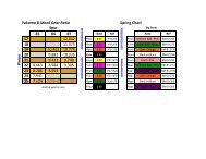
Consult your high-performance shop for recommendations to suit your racing style and class. The chart below lists some of the more<br />
common motor types and a recommended initial gearing for that motor. Ratios can be adjusted depending on various track layouts, tire sizes,<br />
and battery types.<br />
RECOMMENDED INITIAL GEARING FOR COMMON MOTORS<br />
TYPE OF MOTOR PINION SPUR<br />
24 o Stock 20-22 78<br />
10-Turn Modified 19 78<br />
11-Turn Modified 20 78<br />
12-Turn Modified 21 78<br />
13-Turn Modified 22 78<br />
14-Turn Modified 23 78<br />
15-Turn Modified 24 78<br />
16-Turn Modified 25 78<br />
TABLE OF CONTENTS<br />
1. INTRODUCTION .................................................................... i<br />
Completed Kit Dimensions .................................................... i<br />
Notes & Symbols .................................................................. i<br />
Kit Manual Organization ....................................................... i<br />
Important Safety Notes ......................................................... i<br />
Tools Required ..................................................................... ii<br />
Radio/Electrical .................................................................... ii<br />
Hardware Identification ........................................................ ii<br />
Recommended Gearing ......................................................... ii<br />
2. BAG A ..................................................................................1-2<br />
3. BAG B ..................................................................................3-7<br />
4. BAG C ................................................................................ 8-11<br />
5. BAG D ............................................................................. 12-19<br />
6. BAG E ............................................................................. 20-23<br />
7. BAG F ................................................................................... 24<br />
8. BAG G ............................................................................. 25-30<br />
9. Checklist Before Your First Run ......................................... 31<br />
10. Tips From the <strong>Team</strong> ........................................................ 31-33<br />
11. Spare Parts List ............................................................. 34-36<br />
<strong>Team</strong> <strong>Losi</strong> is continually changing and improving designs; therefore, the actual part may appear slightly different than the illustrated part. Illustrations of parts and<br />
assemblies may be slightly distorted to enhance pertinent details.<br />
ii
BAG A<br />
Step A-1<br />
Servo Saver Assembly:<br />
6<br />
6<br />
q 1. Place the Servo Saver Bottom (1) over the Servo Saver Post (2)<br />
and slide the Servo Saver Bottom all the way against the hex at the<br />
opposite end. Be sure that the hex on the Servo Saver Post is inserted<br />
into the hex in the Servo Saver Bottom.<br />
q 2. Slide the Servo Saver Top (3) down over the Servo Saver Post<br />
so that the 'V' area of the Servo Saver Top rests in the 'V' area of the<br />
Servo Saver Bottom. The arm on the Servo Saver Top and the arm on<br />
the Servo Saver Bottom should now point in opposite directions as<br />
shown in Figure 1.<br />
q 3. Slide the Servo Saver Spring (4) over the Servo Saver Post and<br />
push it into the recessed area of the Servo Saver Top. Install the<br />
Servo Saver Spring Cap (5) and thread the 6-40 Locknut (6) onto the<br />
end of the Servo Saver Post.<br />
q 4. Tighten the 6-40 Locknut all the way down and then loosen it<br />
two full turns (e.g. 360 o x 2). This is a good starting point for the<br />
adjustment. Once assembly is complete, if you wish, the servo saver<br />
can be adjusted tighter or looser.<br />
Step A-2<br />
Ball Stud Install:<br />
4<br />
2<br />
5<br />
3<br />
Figure 1<br />
1<br />
11<br />
7<br />
q 1. Insert a 4-40 Mini-Locknut (7) into the outer hex area in the<br />
Servo Saver Bottom (1) and steering Idler Arm (8) as shown in Figure<br />
2. Thread a 3/16" Ball Stud (11) through the outside hole in each arm,<br />
into the Nuts, and tighten. Insert a 4-40 Mini-Locknut into the hex<br />
area in the Servo Saver Top (3). Thread a 3/16" Ball Stud through the<br />
hole in the Arm, into the Nut, and tighten.<br />
q 2. Insert a 4-40 Mini-Locknut into the hex areas in the rear holes<br />
of the Servo Saver Bottom and the steering Idler Arm as shown in<br />
Figure 2. Thread a 3/16" Ball Stud through the Arms, into each Nut,<br />
and tighten.<br />
Once assembly of your new <strong>XXX</strong>-<strong>BK2</strong> is complete, you may<br />
notice that the tires toe-in slightly as the suspension compresses.<br />
We have found this setting to yield the best performance. Should<br />
you prefer to change this so that the tires do not toe in, you can add<br />
one Ball Stud Washer under the Ball Studs on the outside of the<br />
Servo Saver assembly and steering Idler Arm. To accomplish this,<br />
you will want to replace the 3/16" Ball Studs with 1/4" Ball Studs.<br />
Step A-3 Servo Link:<br />
8<br />
3<br />
7<br />
1<br />
Figure 2<br />
11<br />
1<br />
q 1. Snap one end of the steering Draglink (12) to the rear Ball Stud<br />
(11) on the Servo Saver Bottom (1). Snap the other end to the Rear<br />
Ball Stud on the steering Idler Arm (8).<br />
*NOTE: Be sure to snap the rod onto the correct ball studs as shown!<br />
8<br />
11<br />
1<br />
12<br />
Figure 3
BAG A (Continued)<br />
Step A-4<br />
Steering Install:<br />
17<br />
13 16 17<br />
q 1. Insert a 3/32" x 3/16" Ball Bearing (13) into the two large, angled<br />
holes in the bottom of the front Kickplate (14). Insert the other two<br />
Bearings into the two outer holes in the Steering Brace (15).<br />
q 2. Insert a 3/32" x .930" Hinge Pin (16) through the hole in the<br />
steering Idler Arm (8) and center the Hinge Pin in the Idler Arm. Place<br />
the Servo Saver assembly and the steering Idler Arm into the Bearings<br />
in the Kickplate so that the installed Draglink is to the front as<br />
shown in Figure 4.<br />
q 3. Place the Steering Brace on top of the Servo Saver assembly<br />
and steering Idler Arm ensuring that the Ball Bearings slide over the<br />
Pins.<br />
There is a short Thread-Cutting Screw included in the Wrench<br />
bag. This Screw can be used to tap threads in the holes in the Kickplate.<br />
Pre-tapping these holes makes it easier to install the Screws during<br />
assembly.<br />
q 4. Secure the Steering Brace to the Kickplate using two 4-40 x 3/8"<br />
Cap Head Screws (17).<br />
Step A-5 Threaded Insert Install:<br />
15<br />
13<br />
16<br />
14<br />
Figure 4<br />
18<br />
18<br />
q 1. Install a Threaded Insert (18) into the top of each of the two<br />
forward holes in the main Chassis (19). The inserts should be installed<br />
with the hex-side up as shown in Figure 5. Press the Threaded<br />
Inserts all the way into the holes in the Chassis, lining up the hex on<br />
the inserts with the hex in the holes.<br />
19<br />
Figure 5<br />
Step A-6<br />
Kickplate Install:<br />
There is a short Thread-Cutting Screw included in the wrench<br />
bag. This Screw can be used to tap threads into the back two holes in<br />
the front part of the main Chassis. Pre-tapping these holes makes it<br />
easier to install the Screws during assembly.<br />
IMPORTANT NOTE: Ensure that the hex of the Threaded<br />
Insert remains seated in the hex area on top of the Chassis.<br />
q 1. Attach the front Kickplate (14) to the bottom of the main Chassis<br />
(19). Align the four holes in the Kickplate with the four holes in<br />
the main Chassis. Secure the Kickplate to the Chassis by threading<br />
two 4-40 x 3/8" Cap Head Screws (17) through the forward holes and<br />
into the Threaded Inserts (18). Thread two more 4-40 x 3/8" Cap Head<br />
Screws through the two rear holes of the Kickplate and into the Chassis.<br />
17<br />
Figure 6<br />
19<br />
17<br />
14<br />
2
BAG B<br />
Step B-1<br />
Front Bulkhead Install:<br />
19<br />
21<br />
21 54<br />
There is a short Thread-Cutting Screw included in the Wrench<br />
bag. This Screw can be used to tap threads into the middle bottom<br />
hole in the front Bulkhead. Pre-tapping this hole makes it easier to<br />
install the Screw during assembly.<br />
q 1. Position the front Bulkhead (20) on top of the front Kickplate<br />
(14) and main Chassis (19) as shown in Figure 7. Secure the front<br />
Bulkhead to the Chassis by threading two 4-40 x 3/8" Button Head<br />
Screws (21) through the hole in the top of the Bulkhead and into the<br />
Threaded Inserts in the Chassis.<br />
q 2. Secure the front Kickplate to the front Bulkhead by threading a<br />
4-40 x 3/8" Flat Head Screw (54) through the center hole in the front of<br />
the Kickplate and into the Bulkhead.<br />
Figure 7<br />
14<br />
20<br />
54<br />
Step B-2<br />
Front Shock Tower Assembly:<br />
89<br />
24<br />
89<br />
25<br />
q 1. Insert two 4-40 x 3/4" Cap Head Screws (89), one on each side<br />
through center holes in the top of the Front Shock Tower (24). Secure<br />
the Screws to the Shock Tower by threading a 4-40 Nut (25) over each<br />
Screw and tightening.<br />
25<br />
Figure 8<br />
Step B-3<br />
Front Shock Tower Install:<br />
24<br />
26<br />
9 21<br />
26<br />
IMPORTANT NOTE: The Screws in the top of the Shock Tower<br />
must be pointing forward as shown in Figure 9.<br />
q 1. Attach the front Shock Tower (24) to the front Bulkhead (20)<br />
9<br />
with four 4-40 x 3/8" Button Head Screws (21). The Screws thread into<br />
the top-most and bottom-most holes in the Bulkhead, corresponding<br />
with the appropriate holes in the front Shock Tower. The center holes<br />
are not used.<br />
20<br />
q 2. Place one Ball Stud Washer (9) over each of the two 3/8" Ball<br />
Studs (26). Thread a 3/8" Ball Stud into the outside of the three camber<br />
position holes, on each side of the front Bulkhead. Figure 9<br />
3<br />
21
Step B-4<br />
Front Spindle Assembly:<br />
BAG B (Continued)<br />
27 31 32<br />
28<br />
*NOTE: If the 3/16" x 3/8" Bearing only has one Teflon seal<br />
(colored, woven-looking) in it, position the bearing so that the seal<br />
faces the outside of the Spindle.<br />
q 1. Insert a 3/16" x 3/8" sealed Bearing (27) into each side of both<br />
front Spindles [left (28), right (29)].<br />
q 2. Insert a front Stub Axle (30) from the outside of both Spindles as<br />
shown in Figure 10.<br />
q 3. Place a front Axle Spacer (31) over each of the two front Stub<br />
Axles as shown in Figure 10. Thread a 4-40 x 1" Button Head Screw<br />
(32) into each of the Stub Axles from the back side. The front Axle<br />
Spacer should be positioned on the Stub Axle between the head of<br />
the Screw and the inner sealed Bearing. Tighten the Screws while<br />
holding the Stub Axle with a 3/8" socket wrench or pliers.<br />
Be sure that the front Axle Screws are TIGHT! The thread-lock<br />
compound that is on the Screws takes 24 hours to cure.<br />
30<br />
27<br />
Figure 10<br />
32<br />
31<br />
Step B-5<br />
Front Spindle to Spindle Carrier:<br />
35<br />
36 37<br />
33<br />
36<br />
q 1. Attach the left Spindle (28) to the left Spindle Carrier (33) by<br />
aligning the holes in each part and inserting a 3/32" x 1.050" Hinge Pin<br />
(35) from the bottom. Do not insert the Pin all the way through both<br />
parts yet.<br />
q 2. Insert a front Spindle Spacer (36) between the top of the Spindle<br />
and the Spindle Carrier as shown in Figure 11. Once the Spacer is in<br />
place, insert the Hinge Pin through the Spacer and the top of the<br />
Spindle Carrier. Center the Hinge Pin in the Spindle Carrier.<br />
IMPORTANT NOTE: There are two different sizes of E-clips in<br />
this assembly bag. Be sure to use the smallest E-clips on the 3/32"<br />
Hinge Pins. Refer to Figure 11 and make sure that the Spindles are<br />
installed correctly.<br />
q 3. Secure the Hinge Pin with two 3/32" E-clips (37), one on each<br />
end.<br />
q 4. Repeat Steps 1-3 for the right Spindle (29) and right Spindle<br />
Carrier (34).<br />
35<br />
Figure 11<br />
37<br />
28<br />
4
BAG B (Continued)<br />
Step B-6<br />
Ball Stud To Front Spindle:<br />
33<br />
7 10<br />
10<br />
7<br />
q 1. Insert a 4-40 Mini Locknut (7) into the hex area on the back side<br />
of each Spindle Carrier (33), (34) as shown in Figure 12. Insert a 1/4"<br />
Ball Stud (10) into the outside hole (closest to the installed Hinge Pin)<br />
and tighten.<br />
q 2. Insert a 4-40 Mini Locknut into the hex area in the top side of<br />
each Spindle (28), (29). Thread a 1/4" Ball Stud into the Nut from the<br />
bottom of the Spindle and tighten.<br />
28<br />
IMPORTANT NOTE: Do not overtighten the Ball Studs! This<br />
can strip out the hex area in the Spindles and cause the Spindle Carrier<br />
to crack/break.<br />
10<br />
Figure 12<br />
Step B-7<br />
Front Suspension Arm Assembly:<br />
166 40<br />
41<br />
37<br />
IMPORTANT NOTE: There are two sizes of E-clips in this assembly<br />
bag. Be sure to use the small E-clips on the 3/32" Pins.<br />
q 1. Place the left Spindle and Carrier assembly (Figure 12) into a<br />
front suspension Arm (38) as shown in Figure 13. Note that the Spindle<br />
Arm faces the side of the suspension Arm with the Shock mount<br />
holes (rear) and the Ball Stud (10) in the Spindle Carrier is pointing<br />
forward. Line up the two sets of holes in the Spindle Carrier (33) with<br />
the holes in the front Arm, insert a 3/32“ x .930" Hinge Pin (166) in the<br />
inside of the outer two holes of the Arm and Spindle Carrier then<br />
attach a 3/32” E-clip (37) to both sides of the Hinge Pin.<br />
q 2. Install a 1/8" E-clip (41) on one end of each inner 1/8" x 1.42"<br />
Hinge Pin (40).<br />
q 3. Attach the Arm to the left side of the front Pivot Block (39) by<br />
inserting Hinge Pin from the back side, through the inside hole in the<br />
front Arm, and Pivot Block as shown in Figure 13.<br />
q 4. Repeat Steps 1-3 for the right Spindle and Carrier assembly and<br />
remaining front suspension Arm.<br />
q 5. Slide the front Hinge Pin Brace (42) over both front inner Hinge<br />
Pins. The E-clip grooves in both Hinge Pins should be exposed in<br />
front of the Brace. Secure the Brace by installing a 1/8" E-clip to the<br />
front of each Hinge Pin.<br />
The <strong>XXX</strong>-<strong>BK2</strong> has been designed with Varaible Length Arms<br />
(VLA). For a more detailed description of the VLA system, please<br />
read the VLA section in the back of this manual.<br />
42<br />
41<br />
166<br />
40<br />
39<br />
37<br />
38<br />
41<br />
33<br />
10<br />
IMPORTANT NOTE: Make sure that the Hinge Pin is installed<br />
into both of the inner-most holes on the VLA Arms and Spindle Carriers.<br />
Figure 13<br />
5
Step B-8<br />
BAG B (Continued)<br />
Front Suspension Arm Install:<br />
150<br />
43<br />
150<br />
q 1. Hold the Chassis assembly upside down. Place the front Pivot<br />
Block (39) over the front edge of the front Kick plate (14) as shown in<br />
Figure 14. The front edge of the front Bulkhead (20) should be positioned<br />
between the front Pivot Block and the Hinge Pin Brace (42).<br />
q 2. While holding the front suspension assembly in place, position<br />
the front Bumper (43) on the bottom of the front Pivot Block so that<br />
the four holes in the Bumper are aligned with the four holes in the<br />
Pivot Block. The Bumper should be attached as shown so that the<br />
edges curve towards the top of the Chassis. Secure the Bumper and<br />
Pivot Block to the front Bulkhead and Kickplate by threading four 4-<br />
40 x 5/8" Flat Head Screws (150) through the Bumper and Pivot Block<br />
and tightening.<br />
42<br />
14<br />
20<br />
Figure 14<br />
39<br />
Step B-9<br />
Tierod - Camber Link Assembly:<br />
45<br />
46<br />
45<br />
46<br />
There is a small container/package of White Grease in this bag.<br />
It is recommended that this be applied to the threads of the Turnbuckles<br />
before trying to thread on the plastic Rod Ends.<br />
*NOTE: The two ends of the turnbuckle are threaded opposite.<br />
The end closest to the groove, next to the square, has standard<br />
right-hand threads, the other end has left-hand threads. This allows<br />
the length of the Tierods, once installed, to be adjusted without<br />
removing them.<br />
q 1.Thread a plastic Rod End (45) onto each end of a<br />
1-5/8" Turnbuckle (46). Tighten both Rod Ends equally until the Tierod<br />
is the same length as the Rod in Figure 15B. Make two of these<br />
camber link assemblies.<br />
Step B-10<br />
Camber Link Install:<br />
Figure 15A<br />
Figure 15B<br />
*NOTE: Assure that the grooves on all of the front Turnbuckles<br />
are located on the drivers right-hand side for easier adjustment<br />
later.<br />
q 1. Place a "Foam Thing" (47) over the Ball Studs (10) in each of the<br />
Spindle Carriers (33), (34). Next, attach one side of a camber link assembly<br />
(Figure 15B) to the Ball Stud (26) on the left side of the Bulkhead.<br />
Attach the other side of the camber link assembly to the Ball<br />
Stud in the Spindle Carrier.<br />
q 2. Attach the second camber Tierod to the right side of the car.<br />
20<br />
26<br />
Figure 16<br />
47<br />
33<br />
6
BAG B (Continued)<br />
Step B-11<br />
Steering Tierod:<br />
45<br />
72<br />
72<br />
There is a small container/package of White Grease in this bag.<br />
It is recommended that this be applied to the threads of the Turnbuckles<br />
before trying to thread on the plastic Rod Ends.<br />
*NOTE: The two ends of the turnbuckle are threaded opposite.<br />
The end closest to the groove, next to the square, has standard<br />
right-hand threads, the other end has left-hand threads. This allows<br />
the length of the Tierods, once installed, to be adjusted without<br />
removing them.<br />
q 1. Thread a Plastic Rod End (45) onto each End of a<br />
1-7/8" Turnbuckle (72). Tighten both Rod Ends equally until the Rod<br />
is the same length as the Rod in Figure 17B. Make two of these Tierod<br />
assemblies.<br />
45<br />
Figure 17B<br />
Figure 17A<br />
Step B-12<br />
Steering Tierod Install:<br />
*NOTE: Assure that the grooves on all of the front Turnbuckles<br />
are located on the drivers right-hand side for easier adjustment<br />
later.<br />
q 1. Place a "Foam thing" (47) over the Ball Studs (10) in each of the<br />
Spindle (28), (29).Snap one end of a steering Tierod assembly (Figure<br />
17B) to the Ball Stud (11) in the steering Servo Saver Bottom (1). Snap<br />
the other end to the Ball Stud (10) in the left Spindle (28).<br />
q 2. Attach the second steering Tierod to the right side of the car.<br />
28<br />
10<br />
11<br />
47<br />
1<br />
Figure 18<br />
7
BAG C<br />
Step C-1 CVD Dogbone Assembly:<br />
60 61 63<br />
q 1. Apply a thin coat of White Thrust Bearing/Assembly Grease<br />
(87) to the outside of the CVD Coupling (60). Insert the greased Coupling<br />
into the large hole in the rear Axle (62) so that the hole in the<br />
Coupling can be seen through the slots in the Axle.<br />
q 2. Place the CVD Dogbone (59) over the rear Axle. Align the holes<br />
in the Dogbone with the hole in the Coupling. Secure all three parts<br />
by inserting a 1/16" x 7/16" (solid) Coupling Pin (61) through the<br />
holes in the Dogbone, the slots in the rear Axle, and the hole in the<br />
Coupling.<br />
61<br />
59<br />
62<br />
IMPORTANT NOTE: Apply the enclosed thread-lock to the Set<br />
Screw before threading it into the CVD Coupling. If Thread Lock is<br />
not used, the Set Screw could loosen during operation causing your<br />
CVD to possibly fail or be damaged.<br />
q 3. Center the Pin in the Dogbone and secure it by threading a 4-40<br />
Setscrew (63) into the end of the Coupling.<br />
q 4. Build two of these assemblies.<br />
63<br />
60<br />
Figure 19<br />
Step C-2<br />
Rear Hub Assembly:<br />
22 27 67 69 7 68<br />
q 1.Thread a silver colored Ball Stud (22) into the inside hole of the<br />
left rear Hub (66), from the front (the side without the recessed area)<br />
and secure it with a 4-40 Mini-Nut (7) as shown in Figure 20.<br />
IMPORTANT NOTE: Do not overtighten the Ball Studs.<br />
q 2. Place a "Foam Thing" (47) over the Ball Stud.<br />
*NOTE: If the 3/16" x 3/8" Bearings only have one Teflon seal<br />
(colored, woven-looking) in it, position the seal to the outside of<br />
the Hub.<br />
q 3. Press a 3/16" x 3/8" sealed Bearing (27) into the inside of the left<br />
rear Hub. Slide a rear Axle (62) through the sealed Bearing in the rear<br />
Hub.<br />
q 4. Slide an inner rear Bearing Spacer (67) over the rear Axle, from<br />
the outside, against the inside of the Bearing. Place a second 3/16" x<br />
3/8" Bearing over the rear Axle and press the Bearing into the outside<br />
of the rear Hub.<br />
q 5. Place a rear Axle Spacer (68) over the rear Axle, small side first,<br />
against the outside Bearing.<br />
q 6. Secure the rear Axle and the rear Axle Spacer by inserting a<br />
1/16" x 7/16" Spirol Pin (69) through the small hole in the rear Axle.<br />
The Pin should be centered in the rear Axle.<br />
q 7. Repeat Steps 1-6 for the right rear Hub (65).<br />
69<br />
7<br />
62<br />
47<br />
22 27<br />
66 67<br />
Figure 20<br />
27<br />
68<br />
8
Step C-3<br />
BAG C (Continued)<br />
Rear Hub Assembly Install:<br />
41 70<br />
71<br />
q 1. Place the left rear Hub (66) between the outer rails of the left<br />
rear suspension Arm (51) (Marked "L"). Be sure that the Ball Stud<br />
(22) is pointed towards the front of the Arm. Position a rear Hub<br />
Spacer (70) between the Hub and the Suspension Arm on each side<br />
of the Hub.<br />
q 2. Insert the outer rear Hinge Pin (71) into the inside hole on the<br />
Suspension Arm, through each of the two Hub Spacers and the<br />
inside hole in the rear Hub. Secure the Hinge Pin with two 1/8" E-<br />
clips (41).<br />
q 3. Repeat Steps 1 and 2 for the right rear Hub (65) assembly.<br />
*Note: Read the VLA section in the back of this manual for<br />
tips on when to use the outer holes on the rear Arms and Hubs..<br />
51<br />
71<br />
41<br />
Figure 21<br />
22<br />
70 66<br />
Step C-4<br />
Rear Arm & Suspension Assembly Install:<br />
52<br />
44 54 165<br />
q 1. Attach the plastic rear inner Pivot Block (49) to the rear Pivot<br />
Plate (53) with two 4-40 x 1/2" Flat Head Screws (44) with the Hinge<br />
Pin holes facing rearward. Thread the Flat Head Screws in 3-4 turns<br />
to hold the plastic rear Pivot in place.<br />
q 2. Locate the small Anti-Squat Shims (165) (read the "Anti-Squat"<br />
section in "Tips" for when to use more or less of these). Place one<br />
Anti-Squat Shim between the plastic rear Pivot and the rear Pivot<br />
Plate , making sure the flat edge is towards the outside, and tighten<br />
the two Screws.<br />
19<br />
49<br />
IMPORTANT NOTE: Ensure that the Anti-Squat Shims are completely<br />
under the plastic rear Pivot to provide a rigid mounting surface.<br />
q 3. Attach the rear Pivot Plate to the Chassis (19) using four<br />
4-40 x 3/8" Flat Head Screws (54). Make sure the Pivot Plate is flush<br />
with the Chassis, and the holes in the Pivot Plate and Chassis are<br />
aligned.<br />
q 4. Slide the a rear inner Hinge Pin (52) into the left rear suspension<br />
Arm (51) marked 'L' push the hinge pin into the left side of the plastic<br />
rear Pivot Block.<br />
q 5. Repeat Step 4 for the right rear suspension Arm.<br />
q 6. Slide the aluminum rear Pivot (164) over the rear inner Hinge<br />
Pins with the flat side facing towards the rear of the car. Thread two<br />
4-40 x 3/8" Flat Head Screws through the Pivot Plate into the aluminum<br />
rear Pivot, do not tighten them at this time!<br />
51<br />
52<br />
164<br />
53 54<br />
44<br />
REAR INNNER<br />
PIVOT SCREWS<br />
165<br />
IMPORTANT NOTE: The screws holding the aluminum Rear<br />
Pivot will have to be removed later to allow for the installation of the<br />
Motor Guard, it is important that these Screws are only snug at this<br />
time.<br />
Figure 22<br />
9
Step C-5<br />
BAG C (Continued)<br />
Rear Shock Tower Assembly:<br />
22<br />
23 25 57<br />
q 1. Insert two 4-40 x 7/8" Cap Head Screws (23), one on each side,<br />
through the second hole out on the top of the rear Shock Tower (55)<br />
as shown in Figure 23. Secure the Screws to the Shock Tower by<br />
threading a 4-40 Nut (25) onto each Screw and tightening.<br />
55<br />
25<br />
IMPORTANT NOTE: The Screws should extend from the same<br />
side of the Shock Tower as the two tabs near the center of the Shock<br />
Tower.<br />
q 2.Thread a silver colored Ball Stud (22) into the center hole on<br />
each side of the rear Shock Tower.<br />
23<br />
57<br />
IMPORTANT NOTE: The Ball Stud installed in the rear shock<br />
tower, must be a silver colored "Short Neck" Ball Stud.<br />
q 3. Align a rear Wing Mount (56) with the lower set of holes in the<br />
left side of the rear Shock Tower. Secure the Wing Mount with two 4-<br />
40 x 1/2" Cap Head Screws (57). Align and secure the other Wing<br />
Mount to the right side of the Shock Tower in the same manner.<br />
56<br />
IMPORTANT NOTE: The Wing Mounts should extend from<br />
the Shock Tower in the opposite direction of the Screws in the top of<br />
the Tower as shown in Figure 23.<br />
22<br />
Figure 23<br />
Step C-6<br />
Rear Shock Tower Install:<br />
54 57 58<br />
55<br />
57<br />
58<br />
There is a short thread-cutting screw included in the Wrench<br />
bag. This Screw can be used to tap threads in the holes in the Main<br />
Chassis. Pre-tapping these holes makes it easier to install the Screws<br />
during assembly.<br />
q 1. Place the rear Shock Tower (55) between the rear Suspension<br />
Arms and behind the aluminum rear Inner Pivot (164). The Shock<br />
Tower should sit flat against the rear Pivot Plate (53). Place a #4<br />
washer (58) over two 4-40 x 1/2" Cap Head Screws (57). Secure the<br />
Shock Tower to the Chassis by threading the two 4-40 x 1/2" Cap<br />
Head screws, with #4 washers attached, through the tabs on the<br />
Shock Tower and into the Chassis.<br />
q 2. Secure the rear Shock Tower to the rear Pivot Plate by threading<br />
a 4-40 x 3/8" Flat Head Screw (54) from the bottom side of the<br />
Chassis through the Pivot Plate, and into the Shock Tower.<br />
19<br />
54<br />
53<br />
Figure 24<br />
10
BAG C (Continued)<br />
Step C-7<br />
Rear Camber Tierod Assembly:<br />
72<br />
45<br />
46<br />
45<br />
Figure 25A<br />
There is a small container/package of White Grease in Bag B. It is<br />
recommended that this be applied to the threads of the<br />
Turnbuckles before trying to thread on the plastic Rod Ends.<br />
*NOTE: The two ends of the turnbuckle are threaded opposite.<br />
The end closest to the groove, next to the square, has standard<br />
right-hand threads, the other end has left-hand threads. This allows<br />
the length of the Tierods, once installed, to be adjusted without<br />
removing them.<br />
q 1. Thread a plastic Rod End (45) onto each end of the 1-5/8""<br />
Turnbuckles (46). Tighten both Rod Ends equally until the Rod End<br />
is the same length as the one shown in Figure 25B. Make two of these<br />
rear Camber Tierod assemblies.<br />
Figure 25B<br />
Step C-8 Rear Camber Link Install:<br />
55<br />
NOTE: Assure that the grooves on all of the rear Turnbuckles<br />
are located on the drivers left-hand side for easier adjustment later.<br />
q 1. Attach one end of a rear Camber Link assembly (Figure 25B) to<br />
the Ball Stud (22) in the left rear Hub (66) and the other end to the Ball<br />
Stud in the rear Shock Tower (55).<br />
q 2. Repeat Step 1 for the right side of the car.<br />
66<br />
22<br />
Figure 26<br />
11
BAG D<br />
Step D-1<br />
Diff Nut Assembly:<br />
76<br />
73<br />
76<br />
73<br />
q 1. Locate the 5/64" Allen Wrench (74) supplied with the kit. Place<br />
the Diff Nut (73), over the Allen Wrench, with the ears on the Diff Nut<br />
towards the bent end of the Allen Wrench.<br />
q 2. Place the Diff Spring (76) over the Allen wrench against the Diff<br />
Nut.<br />
74<br />
Figure 27<br />
Step D-2<br />
Diff Nut Assembly To Outdrive:<br />
77<br />
q 1. Insert all of the parts that are stacked on the wrench into the<br />
male Outdrive/Diff Half (77). Line up the tabs on the Diff Nut (73) with<br />
the slots in the Outdrive. Make certain that the Diff Spring (76) is<br />
seated all the way into the Outdrive/Diff Half, and that it is flat to the<br />
bottom of the pocket.<br />
73<br />
Leave the Allen Wrench in place to hold the Diff Nut in the<br />
Outdrive while continuing assembly.<br />
Figure 28<br />
76<br />
Step D-3<br />
Diff Drive Ring To Male Outdrive:<br />
79<br />
q 1. Apply a small amount of Diff Grease (clear) (78) to the outside<br />
ridge of the Outdrive/Diff Half (77). Attach a Diff Ring (79) to the<br />
Outdrive by lining up the "D shape" of the Ring with the "D shape"<br />
of the Outdrive.<br />
*NOTE: Only a small amount of Grease is needed. It is only<br />
used to hold the Diff Ring in place.<br />
79 SMALL AMOUNT<br />
OF GREASE<br />
77<br />
IMPORTANT NOTE: Do not glue the Diff Ring to the Outdrive/<br />
Diff Halves. Doing so may not allow the Rings to mount flat on the<br />
Outdrive.<br />
Figure 29<br />
12
Step D-4<br />
Diff Gear:<br />
BAG D (Continued)<br />
80 82<br />
q 1. Insert a 5mm x 8mm Ball Bearing (80) into the center of the Diff<br />
Gear (81).<br />
q 2. Press a 3/32" carbide Diff Ball (82) into each of the 12 small holes<br />
in the Diff Gear. There should be a total of twelve Balls installed.<br />
80<br />
82<br />
GREASE BOTH<br />
SIDES<br />
IMPORTANT NOTE: There are two sets of Balls in Bag D. Be<br />
certain to use the Balls that are packaged separatly (12 total) in Step<br />
D-4. There is a second set of eight 5/64" Balls packaged with Thrust<br />
Washers in the bag. These Balls will be used in Step D-6.<br />
81<br />
Figure 30<br />
Step D-5<br />
Diff Gear to Male Outdrive:<br />
q 1. Apply a small bead of clear Diff Grease (78) to the exposed side<br />
of the Diff Ring (79). Carefully place the Diff Gear(81) over the bearing<br />
boss, so the Diff Balls (82) and Diff Gear rest flat against the Diff Ring.<br />
82<br />
81<br />
IMPORTANT NOTE: It is a good idea to hold the Diff Nut in<br />
place, with the Allen Wrench, so the Diff Nut is not pushed out of the<br />
Outdrive/Diff Half.<br />
GREASE<br />
79<br />
Figure 31<br />
13
BAG D (Continued)<br />
Step D-6<br />
Bearing Insert to Female Outdrive:<br />
75<br />
75 84<br />
85 86 88<br />
*NOTE: Be very careful when installing the foam Thrust Bearing<br />
Seals, do not over-stretch them.<br />
q 1. Locate the Diff Adjusting Screw (84) and carefully stretch the<br />
two blue foam Thrust Bearing Seals (85) into the groves on the head<br />
of the Diff Screw.<br />
q 2. Place one of the Belleville Washers(75) onto the Diff Adjusting<br />
Screw with the cone pointing toward the head of the Diff Screw.<br />
*NOTE: The Thrust Bearing Washers are packaged in a small<br />
bag along with the eight 5/64" Thrust Bearing Balls.<br />
q 3. Place a Thrust Washer (86) on the Diff Screw against the Belleville<br />
Washer.<br />
q 4. Grease the Thrust Washer well with White Thrust Bearing/<br />
Assembly Grease (87) and place the eight 5/64" Thrust Bearing Balls<br />
(88) on top of the Thrust Washer, around the Diff Screw. Apply more<br />
White Thrust Bearing/Assembly Grease to the top of the Thrust Bearing<br />
Balls.<br />
q 5. Place another Thrust Bearing Washer over the Diff Screw and<br />
against the Thrust Bearing Balls.<br />
q 6. Place another Belleville Washer on the Diff Screw with the cone<br />
pointing away from the head of the Diff Screw.<br />
85<br />
84<br />
Figure 32<br />
88<br />
86<br />
GREASE<br />
Step D-7 Diff Adjusting Screw Assembly:<br />
q 1. Very carefully insert the Diff Thrust Assembly, into the female<br />
Outdrive (83). Be very careful to make sure the Thrust Balls(88) remain<br />
seated between the Thrust Washers (86) while inserting the Diff<br />
Screw. Pull the threaded end of the Diff Screw until the Thrust Bearing<br />
assembly rests against the inside of the female Outdrive.<br />
83<br />
IMPORTANT NOTE: Ensure that all eight Thrust Bearing Balls<br />
remain in place between the two Washers, around the Diff Screw.<br />
84<br />
14<br />
Figure 33
Step D-8<br />
BAG D (Continued)<br />
Diff Ring to Female Outdrive:<br />
79 80<br />
79<br />
80<br />
q 1. Insert a 5mm x 8mm Ball Bearing (80) into the center of the<br />
female Outdrive/Diff Half (83).<br />
q 2. Place the 1/16" Allen Wrench (92) through the slot in the Outdrive/<br />
Diff Half containing the Diff Screw (84). Slide the wrench all the way<br />
against the Screw. By handling the Outdrive/Diff Half with the Wrench<br />
inserted, the Diff Screw will be held in place while finishing assembly<br />
of the Differential.<br />
q 3. Apply a small amount of Clear Diff Grease (78) to the outer ridge<br />
of the Outdrive. Install the remaining Diff Ring (79), again lining up<br />
the "D shape" of the Outdrive/Diff Half with the "D shape" of the Diff<br />
Ring. Apply a good size bead of grease to the exposed side of the Diff<br />
Ring.<br />
84<br />
83<br />
SMALL AMOUNT<br />
OF GREASE<br />
92<br />
Figure 34<br />
Step D-9<br />
Diff Assembly:<br />
q 1. Make sure that the slot in the Diff Screw (84) is lined up with the<br />
slot in the female Outdrive/Diff Half (83) and that the Allen Wrench is<br />
inserted in the slot in the Diff Screw.<br />
q 2. Carefully remove the Allen Wrench from Diff Nut in the male<br />
Outdrive. Insert it through the slot of the male Outdrive (same as<br />
what was done with the female Outdrive). This will hold the Diff Nut<br />
in place during assembly.<br />
q 3. While holding the Female Outdrive/Diff Half with the Allen<br />
Wrench inserted, carefully place the two Outdrive/Diff Halves together.<br />
q 4. Hold the Diff assembly so that the Outdrive/Diff Half with the<br />
Diff Nut (73) is pointing up. Slowly turn the Male Diff Half clockwise<br />
to thread the Diff Screw in the Diff Nut. Thread the two halves together<br />
until the Screw just starts to snug up.<br />
When tightening the diff, tighten the screw a little and then “work”<br />
the diff a little, by holding the Diff Gear and Rotating the Outdrive/<br />
Diff Half. Then tighten the Diff a little more and “work” the diff again.<br />
Continue this until the Diff is tight. This will ensure proper seating of<br />
all the parts in the Diff assembly.<br />
q 5. Tighten the Diff until the Gear (81) cannot be turned while both<br />
of the Outdrives/Diff Halves are being held. Final Diff adjustment<br />
should be made after completion of the car.<br />
73<br />
77<br />
81<br />
84<br />
83<br />
15<br />
Figure 35
Step D-10<br />
BAG D (Continued)<br />
Bearing to Left Gearbox Half:<br />
27 95<br />
q 1. Insert a 3/16" x 3/8" sealed Bearing (27) into the top Bearing seat<br />
of the left Gearbox Half (94).<br />
q 2. Insert a 1/2" x 3/4" Bearing (95) into the lower Bearing seat of<br />
the left Gearbox Half.<br />
*NOTE: If the 1/2" x 3/4" Bearing only has one Teflon seal<br />
(colored, woven looking) in it, position the seal to the outside of the<br />
Gearbox Half.<br />
27<br />
IMPORTANT NOTE: Never allow the Gearbox Halves to come<br />
into direct contact with any type of motor spray/cleaner. The material<br />
used on these parts was selected with performance in mind, and some<br />
motor sprays/cleaners may damage the parts.<br />
94<br />
95<br />
Figure 36<br />
Step D-11<br />
Motor Plate to Right Gearbox Half:<br />
96<br />
27 57<br />
95 98<br />
*Note: Motorplate supplied in kit may look slightly different<br />
than pictured in Figure 37.<br />
q 1. Place the Motor Plate (96) against the outside of the right<br />
Gearbox Half (97) by aligning the hole in the Motor Plate with the<br />
Top Shaft Bearing housing in the right Gearbox Half as shown in<br />
Figure 37.<br />
q 2. Rotate the Motor Plate so that the Screw holes in the Motor<br />
Plate line up with the Screw holes in the Gearbox Half. Secure the<br />
Motor Plate to the Gearbox Half by threading a 4-40 x 1/2" Cap Head<br />
Screw (57) through the hole near the center of the Gearbox Half from<br />
the inside into the hole in the Motor Plate and tighten.<br />
q 3.Insert a 3/16" x 3/8"sealed Bearing (27) into the top<br />
Bearing seat of the right Gearbox Half. Carefully push the Bearing all<br />
the way into the Bearing seat using a pencil or the handle of a hobby<br />
knife. Care should be taken not to damage the seals on the Bearing.<br />
*NOTE: If the 3/16" x 3/8" Sealed Bearing only has one Teflon<br />
seal (colored, woven looking) in it, position the seal to the outside<br />
of the gearbox half.<br />
q 4. Insert a 1/2" x 3/4" sealed Bearing (95) into the lower<br />
bearing seat of the right Gearbox Half.<br />
q 5. Press or lightly tap the Idler Gear Shaft (98), into the hole in the<br />
center of the right Gearbox Half.<br />
16<br />
Figure 37<br />
57<br />
97<br />
95<br />
98<br />
27
Step D-12<br />
BAG D (Continued)<br />
Right Gearbox Half Assembly:<br />
99 100<br />
*NOTE: Be sure there is no flashing left on the Top Shaft Spacer<br />
before you install it into the transimssion.<br />
q 1. Slide the Top Shaft Spacer (99) over the long side of the Top<br />
Shaft (90).<br />
q 2. Insert the Top Shaft, threaded side first, through the Bearing<br />
(27) in the right Gearbox Half (97). Firmly press the Slipper Shaft into<br />
the Right Gearbox Half ensuring the Bearing is properly seated.<br />
q 3. Insert a 1/8" x 3/8" Ball Bearing (100) into each side of the Idler<br />
Gear (101). Place the Idler Gear over the Idler Gear Shaft (98).<br />
97<br />
27<br />
99<br />
101<br />
90<br />
100<br />
IMPORTANT NOTE: Install the Differential so that the head of<br />
the Diff Screw is on the left hand side of the car. This will make for<br />
easier adjustment later.<br />
q 4. Insert the Diff Assembly into the 1/2" x 3/4" Sealed Bearing (95)<br />
in the right Gearbox Half with the Diff Nut (73) side first.<br />
*NOTE: Align the teeth on all Gears when installing the Differential.<br />
95<br />
98<br />
Figure 38<br />
Step D-13<br />
Gearbox Assembly:<br />
102<br />
103<br />
96<br />
q 1. Carefully place the left Gearbox Half (94) over the assembled<br />
right Gearbox Half.<br />
q 2. Thread the 2-56 x 3/8" Cap Head Screw (102) into the lower,<br />
forward hole in the Gearbox Housing from the left side.<br />
q 3. Insert a 4-40 x 1" Cap Head Screw (103) into each of the two rear<br />
holes in the left Gearbox Half and thread them into the Motor Plate<br />
(96) as shown in Figure 39.<br />
IMPORTANT NOTE: The top, forward hole in the Gearbox<br />
Halves remains open at this point. This hole will be used to attach the<br />
Gearbox to the rear Shock Tower.<br />
103<br />
97<br />
94<br />
102<br />
Figure 39<br />
17
BAG D (Continued)<br />
Step D-14<br />
Slipper Clutch Assembly:<br />
107 108 109 110<br />
q 1. Slide the Slipper Backing Plate (104) over the Top Shaft (90), aligning the flat sections on the Top Shaft (90) with the flat sections of the<br />
Slipper Backing Plate.<br />
q 2. Place the Slipper Pad (105) on one side of the 78 tooth Spur Gear (106) and align the notches on the Spur Gear with the notches on the<br />
Slipper Pad.<br />
q 3. Place the Spur Gear, Pad side first, over the Top Shaft. The Slipper Pad should rest against the Slipper Backing Plate.<br />
*NOTE: Ensure that the Slipper Pad remains indexed in the Spur Gear.<br />
q 4. Install the second Slipper Pad to the exposed side of the Spur Gear. Again, align the notches on the Spur Gear with the notches on the<br />
Slipper Pad.<br />
q 5. Place the second Slipper Backing Plate over the Top Shaft so that the large, flat surface of the Backing Plate rests against the Slipper<br />
Pad.<br />
q 6. Place the Slipper Spacer (107), long side first, onto the Slipper Shaft and against the outer Slipper Backing Plate.<br />
q 7. Place the silver Slipper Spring (108) over the Slipper Shaft, followed by the Slipper Spring Retaining Washer (109) and secure with the<br />
4-40 Locknut (110).<br />
IMPORTANT NOTE: Before tightening the Locknut, check to see that the Slipper Pads are properly aligned with the notches on both<br />
sides of the Spur Gear. If not, align them before proceeding.<br />
q 8. Tighten the 4-40 locknut all the way down, and then back it off four complete turns (360 o x 4). This is a good starting point for<br />
adjustment. Final adjustment can be made later.<br />
90<br />
104<br />
105<br />
106<br />
105<br />
104<br />
107<br />
108<br />
109<br />
110<br />
Figure 40<br />
18
Step D-15<br />
BAG D (Continued)<br />
Gearbox Install:<br />
58<br />
112<br />
54<br />
q 1. Place the assembled Chassis (19) on a flat table so that the rear<br />
suspension Arms (50), (51) and Chassis (19) are laying flat on the<br />
table. This will make installing the Gearbox a little easier.<br />
q 2. Insert the ball end of the CVD Dogbones (59) into each of the<br />
Outdrive/Diff Halves (77), (83) and place the Gearbox between the<br />
Rear Pivot Blocks (164) (49). Push the Gearbox forward so that the<br />
top, center portion of the Gearbox fits between the tabs on the rear<br />
Shock Tower (55).<br />
q 3. Hold the rear suspension Arms up so that the CVD's stay in<br />
place, and turn the car over holding the Gearbox in place while doing<br />
so. Align the two holes in the rear of the Gearbox Housing with the<br />
two holes in the rear of the Pivot Plate (53).<br />
q 4. Apply a small amount of White Assembly Grease (87) to each of<br />
the two 4-40 x 3/8" Flat Head Screws (54). Thread the Screws through<br />
the two holes in the back of the Pivot Plate into the Gearbox Halves<br />
(94), (97).<br />
q 5. Place a #4 Washer (58) onto the 4-40 x 1-1/2" Cap Head Screw<br />
(112). Thread the Screw through the hole in the left side of the rear<br />
Shock Tower, through both Gearbox Halves and into the Motor plate<br />
(96).<br />
*NOTE: In order to properly align all parts, it may be necessary<br />
to pull the transmission forward while inserting the screw.<br />
19<br />
112<br />
59<br />
58<br />
51<br />
54<br />
83<br />
Figure 41<br />
53<br />
55<br />
IMPORTANT NOTE: Ensure that the 4-40 x 1-1/2" Cap Head<br />
Screw is threaded into the Motor Plate.<br />
Step D-16<br />
Motor Guard Install:<br />
97<br />
91<br />
54<br />
*NOTE: The Screws, installed in the prevous section,which hold<br />
the Aluminum Rear Pivot to the Pivot Plate will have to be removed,<br />
then reinstalled to allow the Motor Guard to slip into place.<br />
q 1. Slide the bottom of the Motor Guard (111) between the rear<br />
Pivot Plate(53) and the Aluminum Rear Pivot (164) as shown in Figure<br />
42. The top of the Motor Guard should fit over the top edge of the<br />
Gearbox.<br />
q 2. Replace the two Screws which hold the Aluminum Rear Pivot,<br />
using them to capture the Motor Guard, and tighten.<br />
There is a short Thread-Cutting Screw included in the Wrench<br />
bag. This Screw can be used to tap threads in the holes in the Gearbox<br />
Halves. Pre-tapping these holes makes it easier to install the Screws<br />
during assembly.<br />
q 3. Secure the top of the Motor Guard to the top of the Gearbox by<br />
threading a 4-40 x 5/16" Button Head Screw (91) through each of the<br />
two holes in the Motor Guard and into the Gearbox Halves (94), (97).<br />
94<br />
91<br />
164 53<br />
Figure 42<br />
111<br />
19
Step E-1<br />
Shock Cartridge Assembly:<br />
BAG E<br />
113 115<br />
116<br />
*NOTE: THIS STEP WILL ONLY BE USED FOR CAR-<br />
TRIDGE MAINTENANCE , ALL CARTRIDGES IN THIS KIT<br />
HAVE BEEN PRE-ASSEMBLED AT THE FACTORY.<br />
113<br />
115<br />
q 1. Place one Shock O-ring (113) into the Cartridge Body (114),<br />
making sure that the O-ring sits flat in the bottom of the Cartridge<br />
Body.<br />
q 2. Insert the Cartridge Spacer (115) into the Cartridge Body followed<br />
by a second O-ring.<br />
q 3. Once the second O-ring is inserted, it should be flush with the<br />
top of the Cartridge Body, press the Cartridge Cap (116) onto the<br />
Cartridge Body. Make sure the Cartridge Cap is snapped all the way<br />
on.<br />
q 4. Repeat assembly process for the remaining three cartridges.<br />
114<br />
Figure 43<br />
Step E-2<br />
Shock Shaft Install:<br />
118 119<br />
q 1. Place a drop of Shock Fluid (117) on the grooved end of each<br />
Shock Shaft [front (118), rear (119)]. Then slide a Cartridge, hex end<br />
first, down the Shock Shaft toward the threads as shown in Figure 44.<br />
118 119<br />
Figure 44<br />
20
Step E-3<br />
BAG E (Continued)<br />
Shock End Install:<br />
122<br />
120<br />
q 1. Using needle-nose pliers, or small vise grips, grasp the front<br />
Shock Shaft (118) between the grooves and thread a Shock End (120)<br />
onto the Shock Shaft. Thread the Shock End all the way onto the<br />
Shaft until the threads stop.<br />
IMPORTANT NOTE: Use caution when threading the Shock<br />
Ends onto the Shafts. Avoid gouging or scratching the Shock Shaft,<br />
while gripping Shock Shaft with the pliers, by placing a towel over the<br />
shaft, then gripping the portion of the Shaft covered by the towel.<br />
This will work very well to protect the Shock Shaft.<br />
q 2. Repeat Step 1 for the second front Shaft and two rear Shafts.<br />
q 3. Carefully snap a 1/4" Shock Mount Ball (122) into each of the<br />
Shock Ends on each of the Shafts.<br />
122<br />
118<br />
119<br />
Figure 45<br />
Step E-4<br />
Shock Piston Assembly:<br />
Front<br />
Rear<br />
36<br />
41<br />
118 119<br />
q 1. Place a 0.050" Shock Spacer (36) over each of the front Shock<br />
Shafts and move them up against the Shock Cartridges.<br />
q 2. Snap a 1/8" E-clip (41) into the groove closest to the Cartridge<br />
on all four shafts (capturing the Spacers on the front Shock Shafts).<br />
q 3. Slide a #56 (Red) Shock Piston (123) over the end of each Shaft<br />
until it rests against the E-clip. Secure the Pistons to the Shaft with<br />
another 1/8" E-clip placed in the groove now exposed on the top of<br />
the Shaft.<br />
36<br />
123<br />
41<br />
Figure 46<br />
21
BAG E (Continued)<br />
Step E-5 Shock Oil Install:<br />
q 1. Match the short, front Shock Bodies (125) to the short, front<br />
Shock Shafts (118), and the long, rear Shock Bodies (126) to the<br />
long, rear Shock Shafts (119).<br />
q 2. Fill the Shock Bodies with Shock Fluid (127) up to the bottom<br />
of the threads inside the Shock Body.<br />
*NOTE: Be sure to match the front Shock Shafts with the front<br />
Shock Bodies.<br />
q 3. Insert the shaft assembly with the Cartridge against the Shock<br />
Piston (123), (124). Slowly tighten the Cartridge about two full turns<br />
only. With the Cartridge still slightly loose, slowly push the Shock<br />
Shaft down into the Shock Body. This will bleed the excess fluid out<br />
of the Shock. Once the Shock Shaft is all the way in, tighten the<br />
Shock Cartridge the rest of the way.<br />
q 4. Now, with the Shock Shaft still all the way in, secure the<br />
Cartridge by tightening it with pliers or a Wrench approximately 1/8<br />
of a turn. There should be no air in the Shocks as you push the Shaft<br />
in and out. If there is, the Shock needs more Fluid. If the Shock Shaft<br />
does not compress all the way, the Shock has too much Fluid in it.<br />
*NOTE: If leaking persists around the outside, tighten the<br />
cartridge more. Be careful not to over tighten and strip the threads<br />
on the Cartridge Body.<br />
q 5. Repeat Steps 2-4 for the remaining three Shocks.<br />
119 118<br />
124 123<br />
Figure 47<br />
125 126<br />
127<br />
Step E-6 Shock Adjustment Nut Assembly:<br />
*Note: This step will only be used for maintenance<br />
purposes, all of the Shock Adjustment Nuts in this kit<br />
have been pre-assembled at the factory.<br />
*NOTE: Place a drop of Shock Fluid onto each O-ring before<br />
installing it into the Shock Adjusting Nut.This will allow the Nut to<br />
thread onto the Shock Body easily.<br />
q 1. Place the O-ring (5) into the grove inside of the Shock Adjusting<br />
Nut (130), Be sure to seat the O-ring completely into the groove as<br />
shown in Figure 48B.<br />
5<br />
130<br />
Figure 48A<br />
Figure 48B<br />
Step E-7<br />
Shock Install:<br />
130<br />
q 1. Snap a Shock Spring Cup (128) with the small side down, onto<br />
each of the four Shock Shafts (118), (119) and over the Shock End<br />
(120).<br />
q 2. Slide an Orange front (short) Shock Spring (129) over each of<br />
the two front Shocks so that the Spring rests on the Spring Cup. Slide<br />
a Yellow rear (long) Shock Spring (131) over each of the two Rear<br />
Shocks so that the Spring rests on the Spring Cup.<br />
q 3. Thread a Shock Spring Adjustment Nut (130), small side down,<br />
on to the top of all four Shock Bodies (125), (126). Thread the Spring<br />
Adjustment Nuts on to the Shocks until the Adjusting Nut just touches<br />
the Spring.<br />
*NOTE: Final ride height adjustment should be made once the<br />
car is fully built and all radio gear and electrics are installed. Refer to<br />
the setup sheet provided in the back of this manual for final ride<br />
height adjustment.<br />
128<br />
129 131<br />
125 126<br />
118 119<br />
120<br />
22<br />
Figure 49
Step E-8<br />
BAG E (Continued)<br />
Rear Shock Install:<br />
57<br />
110<br />
110<br />
q 1.Position your car so that the Shock mounting holes in the front<br />
of the Arms are accessible. Make sure that the CVD Dogbones (59)<br />
stay in the Outdrives/ Diff halves (77)(83).<br />
q 2. Position the bottom of an assembled rear Shock in front of the<br />
Shock mounting area on the left rear suspension Arm (51). Align the<br />
hole in the Shock Mount Ball (122) with the middle hole in the Arm.<br />
q 3. Attach the Shock to the rear Arm by threading a 4-40 x 1/2" Cap<br />
Head Screw (57) through the Shock Mount Ball all the way into the<br />
middle hole of the suspension Arm.<br />
q 4. Slide a short Shock Mount Bushing (132), large side first, over<br />
the Shock mounting Screw (23) in the top left side of the rear Shock<br />
Tower (55).<br />
q 5. Place the top of the Shock Body (126) over the Shock Mount<br />
Bushing. Secure the Shock to the Shock Tower by threading a 4-40<br />
Locknut (110) onto the Shock Mount Screw.<br />
*NOTE: Before attaching the top of the Shock, make sure that<br />
the CVD Dogbones are in place in the Outdrives.<br />
q 6. Repeat Steps 2-5 for the right rear Shock.<br />
23<br />
132<br />
55<br />
126<br />
122<br />
57<br />
Figure 50<br />
51<br />
Step E-9<br />
Front Shock Install:<br />
57<br />
110<br />
125<br />
110<br />
133<br />
q 1. Insert the Shock End (120) of a front Shock into the Shock<br />
mounting area of the left front suspension Arm (38) and line up the<br />
hole in the Shock Mount Ball (122) with the middle hole in the Arm.<br />
q 2. Secure the Shock to the front Arm by threading a 4-40 x 1/2" Cap<br />
Head Screw (57) all the way into the Arm from the back side.<br />
q 3. Slide a long Shock Mount Bushing (133), large side first, over<br />
the Screw (89) on the left side of the front Shock Tower (24).<br />
q 4. Place the top of the Shock Body (125) over the Shock Mount<br />
Bushing on the front Shock Tower. Secure the Shock to the Shock<br />
Tower by threading a 4-40 Locknut (110) onto the Shock Mount Screw.<br />
q 5. Repeat Steps 1-4 for the right front Shock.<br />
38<br />
122<br />
120<br />
57<br />
23<br />
Figure 51
BAG F<br />
Step F-1<br />
Tire Mounting and Install:<br />
110 140<br />
q 1. Inspect the inside of the Tires [front (134), rear (135)] for any excess material. If present, trim excess rubber to ensure proper seating of<br />
the Tire bead on the Wheel [front (136) , rear (137)]. During Tire assembly, make sure that all lettering on the sidewall of the Tires faces to the<br />
outside of the Wheel.<br />
*NOTE: Do not set Tires on furniture as they may leave permanent stains.<br />
It is recommended that you dampen a corner of a cloth with some rubbing alcohol and use it to clean off any residue from the bead of the<br />
Tire to ensure a clean gluing surface. Be sure to let the alcohol on the Tire dry before inserting the Foam Insert into the Tire.<br />
q 2. Insert the front Foam Liners (138) into the front Tires. Pull the front Tires over the front Wheels and squeeze the Tires to properly seat<br />
the bead into the grooves of the Wheels. Make certain that the Foam Liners are not pinched between the Tires and the Wheels.<br />
q 3. Insert the rear foam Tire Liners (139) into the rear Tires. Pull the rear Tires over the rear Wheels and squeeze the Tires to properly seat<br />
the bead into the grooves of the Wheels. Make certain that the Foam Liners are not pinched between the Tires and the Wheels.<br />
<strong>Team</strong> <strong>Losi</strong> Tire Glue (A-7880 "Thick", A-7881 "Thin") is the best Glue available for gluing R/C car Tires. This Glue was produced<br />
specifically for this purpose. The <strong>Team</strong> <strong>Losi</strong> (A-7884) off-road Tire Gluing kit is also available to get the job done right. It includes a bottle of<br />
glue, an applicator tube, and a ten rubber bands. The rubber bands will be used to properly seat and hold the Tire bead into the Wheel.<br />
IMPORTANT NOTE: Allow the Glue to dry thoroughly before continuing. Read and follow adhesive manufacturers' safety warnings<br />
regarding use.<br />
q 4. The tires now need to be glued to the wheels. This can be done by using a fast-curing superglue or cyanoacrylate glue, available at your<br />
local hobby shop. Install a Tire gluing rubber band to around the outside of the Tire, inline with the bead to hold it onto the Wheel. Now slightly<br />
pull back the bead from the Wheel and apply a thin bead of glue between the Tire bead and the Wheel all the way around, wait for this side to<br />
dry and do the same to the other side until the tire is firmly adhered to the wheel. Allow the glue to dry thoroughly before continuing.<br />
q 5. Install the front Wheels to the front Stub Axles (30) by lining up the hex on the Axle with the Hex area in the front Wheel.<br />
q 6. Secure the front Wheels by threading a 4-40 Locknut (110) onto each of the front Axles and tightening.<br />
q 7. Mount the rear Wheels to the rear Axles (62) by lining up the Roll Pin (69) in the rear Axle with the groove in the rear Wheel and pushing<br />
the Wheel all the way onto the Axle, making sure the Roll Pin is lined up with the slot on the Wheel.<br />
q 8. Secure the rear Wheels by threading the 8-32 Locknuts (140) on to the Rear Axles and tightening.<br />
134<br />
138<br />
135<br />
110<br />
136<br />
Figure 52<br />
137<br />
139<br />
140<br />
24
BAG G<br />
Step G-1<br />
Motor and Gear Cover Install:<br />
58 141 143<br />
q 1. Attach the motor (not included) to the Motor Plate (96) using<br />
two 3mm x 8mm Cap Head Screws (141) and two #4 Washers (58). Do<br />
not tighten the Screws yet.<br />
q 2. Attach the pinion gear (not included) to the motor shaft by<br />
aligning the set screw in the pinion with the flat side on the motor<br />
shaft and tightening. Adjust gear mesh so that there is a little "backlash"<br />
between the Gears, and tighten the Motor Screws one at a time,<br />
checking the mesh between the tightening of each Screw.<br />
*NOTE: The gears need some backlash in order to function<br />
properly. Too much though will cause failure, so be sure to check<br />
the Gear mesh at different points in the rotation of the Spur Gear.<br />
*NOTE: Some of the Gear Covers may come pre trimmed from<br />
the factory, with mounting holes already in place.<br />
q 3. Locate the Gear Cover (142) and cut the back side of it along<br />
the trim line as shown. If not already present, drill three 1/8" mounting<br />
holes in the gear cover at the three locations marked with dimples.<br />
q 4. Place the trimmed Gear Cover over the Motor Plate and secure<br />
it with three 4-40 x 1/8" Button Head Screws (143) through the three<br />
tapped holes in the Motor Plate.<br />
q 5. Install the Gear Cover Plug (144) into the large hole in the Gear<br />
Cover.<br />
Step G-2 Servo Arm Install:<br />
Figure 53A<br />
142<br />
143<br />
96<br />
58<br />
141<br />
Figure 53B<br />
144<br />
11<br />
7<br />
7 11<br />
9<br />
q 1. Using Table 55B (on the following page), determine which<br />
Servo Arm (145) is required for your Servo. If your particular Servo is<br />
not listed, try using the Arm recommended for another Servo made by<br />
the same manufacturer.<br />
Some Servos may require the use of a Ball Stud Washer (9) placed<br />
behind the Ball Stud (11) for proper Servo Link alignment, as shown<br />
in Figure 54A.<br />
q 2. Insert a 4-40 Mini-Locknut (7) into the hex area on the back<br />
side of the Servo Arm. Thread a 3/16" Ball Stud (11) through the hole<br />
in the Servo Arm, into the Locknut, and tighten.<br />
q 3. Plug the Servo into the radio system’s receiver (not included).<br />
Make sure that there is power to the Receiver, and turn the transmitter<br />
on followed by the Receiver. Be sure that the trim settings for the<br />
steering on your transmitter are set to the center. With the radio system<br />
still turned on, attach the Servo Arm to the output shaft so that<br />
the Arm is one spline off center in the direction shown in Figure 54B.<br />
Secure the Servo Arm with the screw supplied with the Servo.<br />
BALL STUD WASHER (9)<br />
REQUIRED FOR SOME<br />
SERVOS<br />
Figure 54B<br />
Figure 54A<br />
145<br />
25
BAG G (Continued)<br />
Figure 55<br />
Table 55A<br />
SERVO TYPE<br />
MOUNTING POST<br />
PIN LOCATION<br />
REQUIRED<br />
SERVO ARM<br />
STEERING LINK<br />
LENGTH<br />
AIRTRONICS<br />
All<br />
4 23 58B<br />
Futaba<br />
S131, S131SH, S148, S3001, S5101,<br />
2 25 58B<br />
S9101,S9201, S9301, S9401, S9403<br />
Futaba<br />
S3401, S9402, S9404, S9450<br />
3 25 58B<br />
Futaba<br />
S9303<br />
4** 25 58B<br />
HiTech<br />
HS-605, HS-615, HS-925, HS-945<br />
3** 24 58C<br />
HiTech<br />
All other's<br />
1 24 58C<br />
JR<br />
NES-507, NES-513, NES-517, NES-901,<br />
NES-4000, NES-4131, NES-4721,<br />
1 23 58B<br />
NES-4735, NES-9021,DS-8231<br />
KO<br />
PS-702, PS-703, PS-1001, PS-1003<br />
2 23 58B<br />
KO<br />
PS-901BH, PS-902<br />
1<br />
23<br />
58B<br />
Multiplex<br />
All<br />
3<br />
23<br />
58B<br />
** Use 1 Ball Stud washer on the ball stud when attaching it to the servo arm.<br />
Table 55B<br />
Step G-3<br />
Servo Mounting Post Install:<br />
17<br />
58<br />
q 1. Use Tables 55A and 55B to determine how the Servo Mounting<br />
Posts (146) should be attached to the Servo (not included).<br />
Trim any flashing from the pins on the Mounting Posts so that<br />
they will seat all the way into the holes in the Chassis and Chassis<br />
Brace.<br />
q 2. Place a #4 Washer (58) over each of the four 4-40 x 3/8" Cap<br />
Head Screws (17) and attach the Servo Posts to the Servo by threading<br />
a Screw through the upper and lower holes in each Post. Do not<br />
tighten the Screws yet! Just snug them up so that the Posts are held<br />
in place, but can still be moved from side to side with a little resistance.<br />
The Screws will be tightened at a later step so that the Posts<br />
have the correct spacing.<br />
146<br />
58<br />
17<br />
Figure 56<br />
26
BAG G (Continued)<br />
Step G-4<br />
Servo Mounting:<br />
17<br />
147<br />
17<br />
q 1. Install the Servo into the Chassis (19) as shown in Figure 57.<br />
Insert the pin on the left Servo Mounting Post (146) into the hole in<br />
the Chassis. Move the Servo and Posts slightly until both the left and<br />
right Posts are inserted in the holes in the Chassis.<br />
q 2. Place the Chassis Brace (147) on top of the Servo. The pins<br />
from both Servo Mounting Posts should line up with the holes on the<br />
bottom of the Chassis Brace. If they do not, move the Posts slightly<br />
until the pins fit into the holes.<br />
*NOTE: The Servo should be as close to centered between the<br />
two Posts as possible<br />
q 3. Remove both the Servo and the Chassis Brace from the car.<br />
While holding the Brace in place, tighten the top two Screws (21),<br />
followed by the bottom two Screws. Holding the brace in place will<br />
help keep the Posts from moving while tightening the Screws.<br />
q 4. Reinstall the Servo and Brace to the Chassis. Ensure that the<br />
pins on both sides of the Servo Posts are in their respective holes,<br />
and secure the Brace to the Chassis with four 4-40 x 3/8" Cap Head<br />
Screws (17).<br />
17<br />
19<br />
146<br />
Figure 57<br />
Step G-5<br />
Servo Link:<br />
149<br />
148<br />
148 149<br />
q 1. Thread a short plastic Rod End (148) onto each end of the<br />
4-40 x 5/8" Set Screw (149).<br />
q 2. Refer to Table 55B to determine the appropriate Servo Link<br />
length for the servo that is installed. Tighten both sides equally until<br />
the Rod is the same length as the one shown in Figure 58B or 58C.<br />
Figure 58B<br />
Figure 58A<br />
Figure 58C<br />
Step G-6<br />
Servo Link Install:<br />
q 1. Attach one end of the Servo Link to the Ball Stud (11) in the<br />
Servo Arm (145) and the other to the Ball Stud in the Servo Saver as<br />
shown in Figure 59.<br />
11<br />
145<br />
27<br />
Figure 59
BAG G (Continued)<br />
Step G-7<br />
Rear Body Mount Install:<br />
Figure 60A<br />
54<br />
151<br />
54<br />
q 1. Insert a 4-40 x 3/8" Flat Head Screw (54) into each of the two<br />
rear Body Mounts (151) from the side with the recess for the head of<br />
the Screw.<br />
q 2. Attach a rear Body Mount to the rear of each side of the<br />
Chassis (19) so that the Posts point, at an angle, towards the rear of<br />
the car as shown in Figure 60A. Secure the Body Mounts by tightening<br />
the Screws.<br />
q 3. Apply the Self Adhesive Battery Insulation Tape (121) to both<br />
inner edges of the battery compartment on the Chassis, as shown in<br />
Fig. 60B.<br />
121<br />
19<br />
19<br />
Figure 60B<br />
Step G-8<br />
Battery Foam/Strap Install:<br />
153<br />
155<br />
154<br />
q 1.Place the Battery Spacing Foam (152) into the<br />
recessed area in the rear of the Chassis (19). The foam should be<br />
positioned against the rear Shock Tower (55).<br />
IMPORTANT NOTE: The Battery Strap can be mounted in one<br />
of two ways. The different offset will accommodate different styles of<br />
batteries. If you will be running matched-type cells, or individual cells<br />
laid out side-by-side, the Foam Strip should be attached on the side<br />
with ribs. The foam should be positioned between these ribs. If, however,<br />
you are using a pre-assembled stick pack, the foam strip should<br />
be attached to the side of the strap opposite the ribs.<br />
q 2. Remove the Backing Tape from the Battery Strap Foam Strip<br />
(153) and attach it to the bottom side of the Battery Hold Down Strap<br />
(154).<br />
q 3. Once the battery pack (not included) is installed, the Battery<br />
Strap (154) will hold the batteries in place. The Battery Strap fits<br />
under the rear "bridge" of the Chassis, between the two ribs on the<br />
bottom, and fits over the post on the front Chassis Brace (147). The<br />
strap is secured to the post with a Body Clip (155).<br />
55<br />
152<br />
19<br />
Figure 61<br />
28
BAG G (Continued)<br />
Step G-9<br />
Receiver Install:<br />
q 1. Cut a piece of Two Sided Tape (156) to the same size as the<br />
bottom of the receiver (not included). Peel one side of the backing<br />
off and stick the Tape to the bottom of the receiver.<br />
q 2. Make sure that the area on the right side of the Chassis (19) is<br />
clean. Wipe this area off with a clean cloth or rag.<br />
*NOTE: Rubbing alcohol can be used to clean any oily residue<br />
that may be present on the Chassis or receiver. Allow the alcohol to<br />
dry before applying the Two Sided Tape.<br />
q 3. Peel the backing off of the Two Sided Tape and install the<br />
receiver to the right side of the Chassis with the antenna wire exiting<br />
the receiver towards the front of the car as shown in Figure 62.<br />
q 4. Run the antenna wire forward to the Antenna Post on the<br />
Chassis. Run the wire into the small hole in the bottom of the Antenna<br />
Mounting Post, and up through the top of the Post.<br />
q 5. Slide the antenna wire through the Antenna Tube (157) (a<br />
small drop of oil in the tube will make this easier) so that the wire<br />
comes out the other end of the tube.<br />
*NOTE: If antenna wire is shorter than the Tube, remove the<br />
Tube and cut off enough of the Tube so that the wire will extend<br />
about 3/4" past the end of the Tube.<br />
q 6. While pulling the wire through the Antenna Tube, slide the<br />
Antenna Tube down and push it firmly into the Antenna Mounting<br />
Post on the main Chassis.<br />
q 7. Fold the wire down over the Antenna Tube and place the<br />
Antenna Cap (158) over the tube and excess wire.<br />
158<br />
157<br />
Figure 62<br />
19<br />
Step G-10<br />
Speed Control Install:<br />
q 1. Cut a piece of Two Sided Tape (156) to the same size as the<br />
bottom of the speed control (not included). Peel one side of the<br />
backing off and stick the Tape to the bottom of the speed control.<br />
q 2. Make sure that the area on the left side of the<br />
Chassis (19) is clean. Wipe this area off with a clean cloth or rag.<br />
*NOTE: Rubbing alcohol can be used to clean any oily residue<br />
that may be present on the chassis or receiver. Allow the alcohol to<br />
dry before applying the two-sided Tape.<br />
q 3. Peel the backing off of the Two Sided Tape and install the<br />
speed control to the left side of the Chassis as shown in Figure 63.<br />
q 4. Run the wire from the speed control through the slot in the left<br />
rail on the Chassis, across the center of the Chassis, and through the<br />
slot in the right rail of the Chassis.<br />
q 5. Plug the speed control wire into the channel 2 slot on the<br />
receiver, then plug the wire from the servo into the channel 1 slot.<br />
Figure 63<br />
29
Painting the Body and Wing<br />
BAG G (Continued)<br />
BODY AND WING PAINTING<br />
Prepare the Lexan Body and Wing for painting by washing them thoroughly (inside and out) with warm water and liquid detergent. Dry both the<br />
Body and Wing with a clean, soft cloth. Use the Window Masks (162) supplied to cover the windows from the inside. A high-quality masking<br />
tape should be used on the inside of the Body to mask off any stripes, panels, or designs that you wish to paint on the Body or Wing. Use<br />
acrylic lacquer, acrylic enamel, or any other paints recommended for Lexan (polycarbonate). Apply paint to the inside of the Body and the<br />
bottom side of the wing. Remove the tape for the next color and continue. Try to use darker colors first. If you use a dark color after a light color,<br />
apply a coat of white over the lighter color before applying the darker color. This will help prevent the darker color from bleeding through the<br />
lighter color.<br />
STICKERS<br />
Apply the stickers after the mounting of the Body and Wing is complete. Cut the stickers from the Sticker Sheet (163) that you wish to apply<br />
to the Body or Wing. Before removing the protective backing, find the desired location. Remove the backing completely and reattach an edge<br />
of the sticker to the shiny side of the backing material. Using the rest of the backing material as a handle, position the sticker and press firmly<br />
into place to complete its application.<br />
Step G-11<br />
Body Trim and Install:<br />
159<br />
155<br />
q 1. After Painting, trim the Body (159) along the trim lines (as<br />
shown in Figure 64, emphasized by the dark shading), there is an<br />
indented trim line around the body which can be used as a guide<br />
for trimming.<br />
q 2. Make four 1/4"-diameter holes at the locations marked with<br />
dimples at the front, right side pod, and rear of the left and right<br />
side pods of the Body. These will be the body mounting and<br />
Antenna Tube holes.<br />
q 3. Install the Body onto the rolling Chassis and secure it with<br />
Body Clips (155) through the post on the front Bulkhead (20), and<br />
through the rear Body Mounts (151).<br />
Figure 64<br />
Step G-12<br />
Rear Wing Install:<br />
161<br />
155<br />
161 155<br />
q 1. Trim the rear Wing (160) along the trim lines as shown in<br />
Figure 65.<br />
q 2. Make two 5/32"-diameter holes in the Wing at the locations<br />
160<br />
marked with dimples.<br />
q 3. Place the rear Wing onto the rear Wing Mounts (56) as<br />
shown in Figure 65. Place a Wing Mount Washer (161) over the<br />
post on each rear Wing Mount.<br />
56<br />
q 4. Secure the rear Wing and Wing Mount Washers to the rear<br />
Wing Mounts by installing a Body Clip (155) through the hole in<br />
the post on each rear Wing Mount. Figure 65<br />
30
FINAL CHECKLIST<br />
BEFORE RUNNING YOUR NEW <strong>XXX</strong>-<strong>BK2</strong> for the first time, you should run down the following checklist in order and<br />
complete the listed tasks. I'm sure you're anxious to get out and run your new <strong>XXX</strong>-<strong>BK2</strong> now that it's built, but following this simple<br />
checklist will help to make your first run with your new car much more enjoyable.<br />
1. Adjust the differential<br />
See: About The Differential, in the tips section.<br />
2. Adjust the slipper<br />
See: Adjusting The Slipper, in the tips section.<br />
3. Check for free suspension movement<br />
All suspension arms should move freely. Any binds will<br />
cause the car to handle poorly. The steering should also<br />
operate very freely.<br />
4. Set the ride height<br />
You should start with the rear ride height where the car<br />
comes to a rest at a height where the dogbones are slightly<br />
below level with the surface. The front ride height should<br />
be set so that the bottom of the chassis is level with the<br />
surface.<br />
5. Adjust the camber<br />
Both front and rear tires should have 1/2 degree of negative<br />
camber (top of the tire leans in). It is critical that both<br />
front and bothrear tires be adjusted the same. With either<br />
end of hte car closest to you, use your assembly wrench<br />
to adjust the tierods. Turn the top of the wrench towards<br />
the center of hte car to shorten the tierods, and the opposite<br />
direction to lengthen them.<br />
31<br />
6. Set the front toe-in<br />
Adjust the front tie rods so that, when the steering is<br />
straight on the transmitter, the front tires are both pointing<br />
straight. It is recommended that you start with the front<br />
toe-in set to zero (no toe-in or toe-out).<br />
7. Charge a battery pack<br />
Charge a battery pack as per battery manufacturer's and/<br />
or charger manufacturer's instructions so that<br />
radio adjustments can be made.<br />
8. Adjust the speed control<br />
Following the manufacturer's instructions, adjust your<br />
speed control, and set the throttle trim on your transmitter<br />
so the the car does not creep forward when not applying<br />
throttle. Make sure that there is not too much brake being<br />
applied when the trigger/stick is in the neutral position.<br />
9. Set transmitter steering trim<br />
The steering trim tab on the transmitter should be adjusted<br />
so that the car rolls straight when you are not touching<br />
the steering wheel/stick. If the servo was installed<br />
correctly, as per Tables 55A and 55B, the wheels should<br />
turn equally to the left and right. If this is not the case,<br />
refer to Table 53A &B and ensure that the steering servo<br />
and rod were properly installed.<br />
TIPS AND HINTS FROM THE TEAM<br />
About The Differential Never allow the diff to slip; that’s what the slipper is for. Before trying to adjust your diff, you need to<br />
tighten the slipper until the spring is fully compressed. Next, hold the spur gear and right rear tire, then try turning the left rear tire<br />
forward. It should be very difficult to turn the left rear tire. If the tire turns easily, the diff is too loose. To tighten the diff, line up<br />
the slot in the diff screw with the groove in the left outdrive. Place the 1/16” Allen wrench through both of these slots. This will<br />
lock the diff screw and the outdrive together. While holding the Allen wrench in place, turn the right rear tire forward about 1/8 of<br />
a turn. Check the differential adjustment again and repeat the tightening process as necessary until the differential is no longer<br />
slipping. See "Adjusting the Slipper" on the following page, and then continue from here. The final differential adjustment<br />
check should be made by placing the car on carpet, grass, or asphalt and punching the throttle. The differential should not slip. If<br />
it does, tighten the diff in 1/8-turn increments as described above until the slippage stops.<br />
Once the diff has been adjusted, it should still operate freely and feel smooth. If the diff screw starts to get tight before the diff<br />
is close to being adjusted properly, the diff should be disassembled and inspected; you may have a problem with the differential<br />
assembly. Refer to the assembly instructions to ensure that the diff is properly assembled and that all parts are properly seated in<br />
the assembly.<br />
There are a few things you should know about differentials. First, when rebuilding your diff, you should always replace the<br />
small, diff nut. Second, after the diff has been run a time or two, it is not uncommon for the balls to seat into the rings and create<br />
a slightly loose adjustment. So, after your first and second runs, check the adjustment to avoid slippage. Third, remember: Never<br />
let the diff slip. Doing so can damage the diff balls, rings, and gear. Always make sure that the slipper will slip before the diff.
Adjusting the Slipper should be done after the diff is properly adjusted. If you have just finished adjusting the differential, loosen<br />
the slipper adjustment nut four full turns (e.g., 360 degrees x 4) to return the adjustment to the setting originally described in the<br />
assembly instructions. To make the final adjustments, place your car on the racing surface and give the car full throttle. The slipper<br />
should slip for one or two feet. If the slipper slips for more than two feet, you’ll need to tighten the adjustment nut. If the slipper<br />
doesn’t slip for at least one foot, back off the adjustment nut 1/8 of a turn and retry. If you can’t hear the slipper when you punch<br />
the throttle, hold the front of the car with the rear wheels still on the track and give the car full throttle. The car should push against<br />
your hand with reasonable force and the slipper only slipping slightly. Don't expect the slipper to make up for poor driving or setup.<br />
You still have to use the throttle and maintain the shocks and chassis. The slipper will help you drive more comfortably and help<br />
accelerate of corners and land jumps.<br />
The Most Sensitive Adjustments, and the most used by the <strong>Team</strong> <strong>Losi</strong> race team, are the number of washers under the front<br />
camber link ball studs and the anti-squat. See these two sections and try to familiarize yourself with the way that these adjustments<br />
affect the handling of the <strong>XXX</strong>-<strong>BK2</strong>.<br />
Ride Height is an adjustment that affects the way your car jumps, turns, and goes through bumps. To check the ride height, drop<br />
one end (front or rear) of the car from about a 5-6 inch height onto a flat surface. Once the car settles in to a position, check the<br />
height of that end of the car in relationship to the surface. To raise the ride height, lower the shock adjuster nuts on the shocks<br />
evenly on the end (front or rear) of the car you are working on. To lower the ride height, raise the shock adjuster nuts. Both left<br />
and right nuts should be adjusted evenly.<br />
You should start with the rear ride height where the car comes to a rest at a height where the dogbones are slightly below level<br />
with the surface. The front ride height should be set so that the bottom of the chassis is level with the surface. Occasionally, you<br />
may want to raise the front ride height to get a little quicker steering reaction, but be careful as this can also make the car flip over<br />
more easily.Every driver likes a little different feel so you should try small ride height adjustments to obtain the feel you like. We<br />
have found that ride height is really a minor adjustment. This should be one of the last adjustments after everything else has been<br />
dialed in. Do not use ride height adjustment as a substitute for a spring rate. If your car needs a softer or firmer spring, change the<br />
spring. Do not think that simply moving the shock nuts will change the stiffness of the spring; it will not!<br />
Rear Hub Camber Location is best set according the settings described in this manual. You should start with the inner hole in<br />
the top of the hub (hole "A"). The outer hole will tend to make the car feel a bit stiffer. This results in the car accelerating straighter<br />
and also makes it a bit eassier to line up for jumps. Moving to the inner hole will typically make the car go through bumps better.<br />
The inner hole may also give the feeling of more steering. This steering generally comes from the rear end though. What this<br />
means is that the rear end of the car may swing a bit more — at times even sliding more.<br />
Rear Camber Link Length can be another useful adjustment. It is virtually impossible to make a blanket statement for exactly<br />
how the length of the camber link will affect the handling under all conditions. The following is our experience with how the length<br />
of the camber link will typically affect the handling of the <strong>XXX</strong>-<strong>BK2</strong>. A longer rear camber link will usually result in more rear<br />
traction. With a longer link, the car can start to drive more square, or point-to-point. This can make it difficult to carve corners at<br />
high speed. A shorter rear camber link will generally result in more steering from the rear of the car due to increased chassis roll.<br />
This can make it easier to change directions quicker, but can cause the rear of the car to roll around if the link is too short. A<br />
shorter rear link will usually go through bumps a bit better than a long link as well.<br />
Front Carrier Camber Location is another adjustment that is almost always run in the standard (outer) location. This location<br />
keeps the car flatter with less roll. The outer location also helps the car stay tighter in turns with a more precise steering feel.<br />
Moving the link to the inner hole will make the steering react slightly slower. The advantage to the inner hole is that it can increase<br />
on-power steering and help the car get through bumps better.<br />
Washers Under the Front Camber Link Ball Stud can be added or removed. This is one of the most important adjustments<br />
on the <strong>XXX</strong>-<strong>BK2</strong> car. You should get a feel for how the number of washers affects the handling. Adding washers will make the car<br />
more stable and keep the front end flatter. Removing washers will make the steering more aggressive. This can be good in some<br />
conditions, but can also make the car difficult to drive in others. The best all-around adjustment is with one washer as per the<br />
assembly instructions.<br />
Front Camber Link Length is another adjustment that is difficult to make a generic statement for as it can have slightly<br />
different results on various conditions. The following is a summary of how this adjustment will usually impact the handling of the<br />
32
<strong>XXX</strong>-<strong>BK2</strong>. A longer front camber link will usually make the car feel stiffer. This will help keep the car flatter with less roll, but can<br />
make the car handle worse in bumpy conditions. A shorter front camber link will result in more front end roll. This will increase<br />
high-speed steering and make the car better in bumps. Too short of a front link may make the car feel twitchy or "wandery"<br />
meaning that it may be difficult to drive straight at high speed.<br />
Front Shock Location can be adjusted easily by simply moving top of the shock to another hole in the shock tower. The standard<br />
location (center hole in the tower) works best on most tracks. Moving the top of the shock out one hole will result in an increase<br />
in steering and the car will react quicker. Moving the top of the shock to the inside hole in the tower will slow the steering response<br />
time and make the car smoother in bumps.<br />
The bottom of the shock can also be moved in or out on the suspension arm. Moving the bottom of the shocks to the inside hole<br />
in the arm will result in more low-speed steering and less high-speed steering. Mounting the shocks in the inside hole will require<br />
limiters in the shocks to limit the travel, and the springs should be changed to stiffer ones. Moving the bottom of the shocks to the<br />
outside hole will reduce overall travel, increase high-speed steering, and reduce low-speed steering. This position may be good for<br />
oval tracks and high-traction surfaces.<br />
Rear Shock Location can be changed just as easily as the front. Again, the standard location is the best place to start for most<br />
tracks. Moving the top of the shock in on the shock tower results in less side-bite (traction in corners) but makes the car smoother<br />
in bumps. Moving the top of the shocks to one of the two outside holes will give the car more forward traction and side bite as well<br />
as keeping the car from bottoming out on big jumps. A softer spring should be used if the shocks are mounted in one of the two<br />
outer holes in the tower.<br />
Moving the bottom of the rear shocks to the outside hole in the arm will improve stability but may not handle bumps as well.<br />
You may also notice that the car is faster in the turns. The downside is that the car will not straighten out or "square up" as well.<br />
Rear Anti-Squat is one of the most commonly used adjustments of the <strong>XXX</strong>-<strong>BK2</strong>. As per assembly instructions, there is 1<br />
degree of antisquat. Adding the additional shims under the front of the block will result in 2 degrees. This will result in less side-bite,<br />
which will cause the car to have more steering from the rear end. It will also give the car more forward traction and get more air<br />
off of large jumps. By removing the shims will result in 0 degrees of antisquat. This will have more side bite but will have less<br />
forward traction and get less air off of jumps.<br />
Rear Hub Spacing can be adjusted by moving the spacers at the front and rear of the hub carrier. You will probably find that the<br />
middle (standard) location works best on just about every track. Spacing the hub back might help on large, high-speed, outdoor<br />
tracks. Spacing the hub forward might help on tight, indoor tracks.<br />
Battery Location is sometimes overlooked, but can be a useful adjustment. Start by running the battery spaced forward. Moving<br />
the battery back can improve rear traction on slippery tracks. Moving the battery back too far can cause the rear end to swing<br />
though turns on some tracks. This is a result of having the weight too far back.<br />
Arm Length Adjustment (VLA), the <strong>XXX</strong>-<strong>BK2</strong> is like having four cars in one. With the addition of a longer arm position, you can<br />
have an aggressive setup by using the standard mounting positions or a more conservative setup by using the longer position. For<br />
most tracks the standard setup will work well, but for extremely bumpy, rutted, and high bite tracks the longer arm length will help<br />
slow the reactions of the car, making it feel less twitchy.<br />
The longer arm setting will help to increase steering during the middle, exit, and during on power turns. It can also be used as<br />
a valuable tuning aid to balance your car if you are experiencing too much chassis roll in the front or rear. For example if the rear<br />
of the car is experiencing too much chassis roll in the front, then the longer arm position could be used to balance the car. For<br />
instance, European tracks often have long sweeping turns, which require a very stable car, the longer arm position should prove<br />
to work very well.<br />
We are sure that you will find the <strong>XXX</strong>-<strong>BK2</strong> to be the most versatile and easiest car to drive fast with great consistency. We<br />
at <strong>Team</strong> <strong>Losi</strong> hope this information helps you to enjoy your <strong>XXX</strong>-<strong>BK2</strong> and racing as much as we do. For the latest in setup and<br />
accessory parts information, visit the <strong>Team</strong> <strong>Losi</strong> website at: www.<strong>Team</strong><strong>Losi</strong>.com<br />
33
SPARE PARTS LIST<br />
KEY # KIT/PART DESCRIPTION PART NO. SPARE PARTS DESCRIPTION<br />
1 SERVO SAVER BOTTOM A-1620 Steering/Servo Mount Assembly (Molded)<br />
2 SERVO SAVER POST A-1610 Steering Hardware Set<br />
3 SERVO SAVER TOP A-1620 Steering/Servo Mount Assembly (Molded)<br />
4 SERVO SAVER SPRING A-1610 Steering Hardware Set<br />
5 O-RING, ALUMINUM SHOCK NUT A-5049 Aluminum Shock Adjusting Nut (4)<br />
6 6-40 LOCKNUT A-1610 Steering Hardware Set<br />
7 4-40 MINI-LOCKNUT A-6306 4-40 Aluminum Mini Nuts (10)<br />
8 STEERING IDLER ARM A-1620 Steering/Servo Mount Assembly (Molded)<br />
9 BALL STUD WASHER A-6215 #4 Narrow Washers (10)<br />
10 1/4" BALL STUD A-6006 Ball Studs w/Rod Ends 4-40 x 1/4" (4)<br />
11 3/16" BALL STUD A-6001 Ball Studs w/Rod Ends 4-40 x 3/16" (4)<br />
12 STEERING DRAGLINK A-1620 Steering/Servo Mount Assembly (Molded)<br />
13 3/32" x 3/16" BEARING A-6912 3/32" x 3/16" Ball Bearings<br />
14 FRONT KICKPLATE A-9713 Front Kickplate, Bulkhead, and Steering - Graphite<br />
15 STEERING BRACE A-9713 Front Kickplate, Bulkhead, and Steering - Graphite<br />
16 STEERING HINGE PIN A-1146 Front Outer & King Pins 3/32" x .960"<br />
17 4-40 x 3/8" CAP HEAD SCREW A-6206 4-40 x 3/8" Cap-Head screws (10)<br />
18 THREADED CHASSIS INSERT A-4224 Threaded Chassis Inserts - Short and Long<br />
19 MAIN CHASSIS A-9905 Main Chassis and Brace - Graphite<br />
20 FRONT BULKHEAD A-9713 Front Kickplate, Bulkhead, and Steering Brace<br />
21 4-40 x 3/8" BUTTON HEAD SCREW A-6229 4-40 x 3/8" Button-Head Screws (6)<br />
22 SHORT NECK BALL STUD A-6007 Studded Balls w/Ends (Short Neck) 0.35"<br />
23 4-40 x 7/8" CAP HEAD SCREWS A-6216 4-40 x 7/8" Cap-Head Screws (10)<br />
24 SHOCK TOWER, FRONT A-1107 Front Shock Tower<br />
25 4-40 PLAIN NUT A-6300 4-40 Hex Nuts (10)<br />
26 3/8" BALL STUD A-6000 Ball Studs w/Rod Ends 4-40 x 3/8" (4)<br />
27 SEALED BEARING, 3/16" x 3/8" A-6903 3/16" x 3/8" Teflon-Sealed Bearings (2)<br />
28 SPINDLE, LEFT A-1122 Front Spindles/Carriers<br />
29 SPINDLE, RIGHT A-1122 Front Spindles/Carriers<br />
30 STUB AXLE, FRONT A-1133 Front Stub Axles and Screws<br />
31 AXLE SPACER A-3016 Axle Spacers (2)<br />
32 4-40 x 1" BUTTON HEAD SCREW A-1133 Front Axles and Screws<br />
33 SPINDLE CARRIER, LEFT A-1122 Front Spindles/Carriers<br />
34 SPINDLE CARRIER, RIGHT A-1122 Front Spindles/Carriers<br />
35 HINGE PIN, FRONT OUTER A-6082 Front Outer & King Pins 3/32" Ti-Nitride<br />
36 SPACER, SPINDLE A-2127 Spacers (1/8" x .060")<br />
37 E-clip, 3/32" A-6103 E-Clips 3/32"<br />
38 SUSPENSION ARM, FRONT A-9700 Front Suspension Arms<br />
39 PIVOT BLOCK, FRONT A-4129 Pivot Block Front<br />
40 HINGE PIN, FRONT INNER A-6089 Hinge Pin 1/8" x 1.42", Ti-Nitride<br />
41 E-clip, 1/8" A-6100 1/8" E-Clips<br />
42 HINGE PIN BRACE, FRONT A-9956 Alum. Front Hinge Pin Brace - Hard anodize<br />
43 FRONT BUMPER A-4131 Front Skidplate/Bumper - Black<br />
44 4-40 x 1/2" FLAT HEAD SCREW A-6220 4-40 x 1/2" Flat-Head Screws (6)<br />
45 LONG BALL CUP A-6005 H.D. 30 Deg Plastic Rod Ends (16) - Black<br />
46 1-5/8" TITANIUM TURNBUCKLE N/A<br />
47 FOAM THING A-6003 Foam Things (Linkage Rings) (24)<br />
48 1/8" x 1/4" WASHER A-6350 #4 and 1/8" Hardened Washers<br />
49 PIVOT BLOCK, INNER REAR A-4127 Pivot Mount and Shims, Forward Rear<br />
50 REAR ARM, RIGHT A-9800 Rear Suspension Arms - Graphite<br />
51 REAR ARM, LEFT A-9800 Rear Suspension Arms - Graphite<br />
52 1/8" x 2-1/8" HINGE PIN A-6094 Inner Rear Hinge Pins, Ti-Nitride<br />
53 PIVOT PLATE, REAR A-9833 Rear Pivot Plate - Graphite<br />
54 4-40 x 3/8" FLAT HEAD SCREW A-6210 4-40 x 3/8" Flat-Head Screws (10)<br />
55 SHOCK TOWER, REAR A-9814 Rear Shock Tower - Graphite<br />
56 WING MOUNT A-4222 Wing Mount Set<br />
57 4-40 x 1/2" CAP HEAD SCREW A-6204 4-40 x 1/2" Cap-Head Screws (10)<br />
34
SPARE PARTS LIST<br />
KEY # KIT/PART DESCRIPTION PART NO. SPARE PARTS DESCRIPTION<br />
58 #4 WASHER A-6350 #4 and 1/8" Hardened Washers<br />
59 CVD DOGBONE A-9985 MIP CVD Rebuild Kit (1)<br />
60 CVD COUPLING A-9933 MIP CVD Rebuild Kit<br />
61 CVD COUPLING PIN A-9933 MIP CVD Rebuild Kit<br />
62 CVD AXLE A-9986 MIP CVD Rear Axle, (.200 Offset)<br />
63 4-40 SET SCREW A-9933 MIP CVD Rebuild Kit<br />
64 ASSEMBLY WRENCH A-6030 Assembly Wrench (version 2)<br />
65 HUB CARRIER, RIGHT REAR A-2128 Rear Hubs<br />
66 HUB CARRIER, LEFT REAR A-2128 Rear Hubs<br />
67 BEARING SPACER, REAR HUB A-9942 Bearing Spacer/Wheel Washer Set<br />
68 SPACER, REAR AXLE A-9942 Bearing Spacer/Wheel Washer Set<br />
69 DRIVE PIN, REAR AXLE A-6401 Pins — Wheels and Gears<br />
70 SPACER, REAR HUB A-2127 Rear Hub Spacers (1/8" x .060")<br />
71 HINGE PIN, REAR OUTER A-6088 Hinge Pins, 1/8" x 1.246", Ti-Nitride<br />
72 1-7/8" TITANIUM TURNBUCKLE N/A<br />
73 DIFF NUT CARRIER A-2911 One-Piece Diff Nut/Carrier<br />
74 5/64" ALLEN WRENCH N/A<br />
75 BELEVILLE WASHER A-2933 Differential Screw, Hardware, and Seal<br />
76 DIFF SPRING A-2933 Differential Screw, Hardware, and Seal<br />
77 MALE OUTDRIVE HALF A-2935 Outdrive Cup/Diff Set<br />
78 DIFF GREASE (CLEAR) A-3065 Silicone Differential Compound<br />
79 DIFF RING A-3070 Transmission Drive Rings (2)<br />
80 5mm x 8mm BEARING A-6907 5mm x 8mm Bearings<br />
81 DIFF GEAR A-3074 Transmission Diff Gear, 46 Teeth<br />
82 3/32" CARBIDE DIFF BALLS A-6951 3/32" Carbide Diff Balls (12)<br />
83 FEMALE OUTDRIVE HALF A-2935 Outdrive Cup/Diff Set<br />
84 DIFF ADJUSTING SCREW A-2933 Differential Screw, Hardware, and Seal<br />
85 FOAM THRUST BEARING SEAL A-2933 Differential Screw, Hardware, and Seal<br />
86 3mm x 8mm THRUST BEARING WASHER A-3099 Full Compliment Thrust Bearing Set<br />
87 WHITE THRUST / ASSEMBLY GREASE A-3066 Assembly Grease<br />
88 5/64" THRUS BEARING BALLS A-3099 Full Compliment Thrust Bearing Set<br />
89 4-40 x 3/4" CAP HEAD SCREW A-6205 4-40 x 3/4 Cap Head Screws (10)<br />
90 TOP SHAFT A-9932 Alum. Gear /Slipper Shaft, 18 Teeth<br />
91 4-40 x 5/16" BUTTON HEAD SCREW A-6245 4-40 x 5/16 Button Head Screws (10)<br />
92 1/16" ALLEN WRENCH N/A<br />
94 LEFT GEARBOX HALF A-2938 Transmission Case Set and Spacer (Gen II)<br />
95 1/2" x 3/4" BEARING A-6908 1/2" x 3/4" Ball Bearings w/Teflon Seal (2)<br />
96 MOTOR PLATE A-2941 Lightened Motor Plate - Black Anodize<br />
97 RIGHT GEARBOX HALF A-2938 Transmission Case Set and Spacer (Gen II)<br />
98 IDLER GEAR SHAFT A-2937 Idler Gear, 32 Teeth, and Shaft<br />
99 TOP SHAFT SPACER A-2938 Transmission Case Set and Spacer (Gen II)<br />
100 1/8" x 3/8" BEARING A-6909 1/8" x 3/8" Ball Bearings (2)<br />
101 IDLER GEAR A-2937 Idler Gear, 32 Teeth, and Shaft<br />
102 2-56 x 3/8" CAP HEAD SCREW A-2940 Transmission Screw Set (Gen II)<br />
103 4-40 x 1" CAP HEAD SCREW A-2940 Transmission Screw Set (Gen II)<br />
104 SLIPPER BACK PLATE A-3132 Slipper Backing Plate<br />
105 SLIPPER PAD A-3123 Slipper Pad<br />
106 78 TOOTH SPUR GEAR A-3981 78T 48-Pitch Kevlar® Spur Gear<br />
107 SLIPPER SPACER A-3124 Slipper Spring, Cup, Spacer, Bushing, and Washer<br />
108 SLIPPER SPRING A-3124 Slipper Spring, Cup, Spacer, Bushing, and Washer<br />
109 SPRING RETAINING WASHER A-3124 Slipper Spring, Cup, Spacer, Bushing, and Washer<br />
110 4-40 LOCKNUT A-6305 4-40 Aluminum Locknuts, Low Profile (6)<br />
111 MOTOR GUARD A-4123 Motor Guard, & Body Mnts. - Black<br />
112 4-40 x 1-1/2" CAP HEAD SCREW A-2940 Transmission Screw Set (Gen II)<br />
113 SHOCK O-RING A-5015 Double O-Ring Shock Cartridge<br />
114 SHOCK CARTRIDGE BODY A-5015 Double O-Ring Shock Cartridge<br />
115 SHOCK CARTRIDGE SPACER A-5015 Double O-Ring Shock Cartridge<br />
35
SPARE PARTS LIST<br />
KEY # KIT/PART DESCRIPTION PART NO. SPARE PARTS DESCRIPTION<br />
116 CAP, SHOCK CARTRIDGE A-5015 Double O-Ring Shock Cartridge<br />
118 SHOCK SHAFT, FRONT A-5060 .6" Titanium Nitrided Shock Shaft<br />
119 SHOCK SHAFT, REAR A-5064 1.0" Titanium Nitrided Shock Shaft<br />
120 SHOCK END A-5079 Shock Ends & Cups (2)<br />
121 BATTERY INSULATING TAPE A-9606 Battery Box Insulation (Diecut)<br />
122 1/4 " SHOCK MOUNT BALL A-2006 Swivel Suspension Balls .250" (8)<br />
123 SHOCK PISTON A-5046 Teflon Shock Pistons #56 (Red)<br />
125 SHOCK BODY, FRONT A-5054 .6" Threaded Shock Body Set w/Nuts<br />
126 SHOCK BODY, REAR A-5055 .9" Threaded Shock Body Set w/Nuts<br />
127 SHOCK FLUID A-5224 <strong>Team</strong> <strong>Losi</strong> Certified Shock Fluid 30wt<br />
128 SHOCK SPRING CUP A-5079 Shock Ends & Cups (2)<br />
129 FRONT SHOCK SPRING A-5129 2" Spring 2.9 Rate (Orange)<br />
130 SHOCK ADJUSTING NUT ALUMINUM A-5049 Threaded Shock Body Adjuster Nuts w/O-rings (4)<br />
131 SHOCK SPRING, REAR A-5148 2.5" Spring 2.0 Rate (Yellow)<br />
132 SHOCK MOUNT BUSHING, SHORT A-5013 Front and Rear Upper Shock Mount Bushings<br />
133 SHOCK MOUNT BUSHING, LONG A-5013 Front and Rear Upper Shock Mount Bushings<br />
134 TIRE, FRONT A-7204S Front Xtra-Wide Tires (Silver) w/Foam<br />
135 TIRE, REAR A-7369R 2.2" Rear X-2000 Tires (Red) w/Foam<br />
136 FRONT WHEEL A-7004 Wide Front (Solid) Wheels -Yellow<br />
137 REAR WHEEL A-7104 Wide Rear (Solid) Wheels - Yellow<br />
138 FRONT FOAM TIRE LINER A-7297 4wd Front Foam Liners - Firm<br />
139 REAR FOAM TIRE LINER A-7398 Buggy Rear Foam Liners - Firm<br />
140 8-32 LOCKNUT A-6310 8-32 Alum. Locknuts (6)<br />
141 3mm x 8mm CAP HEAD SCREW A-6201 3mm x 8mm Cap-Head w/Washers (10)<br />
142 GEAR COVER A-2943 Gear Cover with Access Plug (Gen II)<br />
143 4-40 x 1/8" BUTTON HEAD SCREW A-6212 4-40 x 1/8" Button-Head Screws (4)<br />
144 GEAR COVER PLUG A-3045 Slipper Gear Cover Plug (4)<br />
145 SERVO ARM A-1620 Steering/Servo Mount Assembly (Molded)<br />
146 SERVO MOUNTING POST A-1620 Steering/Servo Mount Assembly (Molded)<br />
147 CHASSIS BRACE A-9905 Main Chassis and Brace - Graphite<br />
148 SHORT PLASTIC ROD END A-6010 30 Degree Rod Ends - Black (16)<br />
149 4-40 x 5/8" SET SCREW A-1615 Short Ball Cups and Threaded Rod<br />
150 4-40 x 5/8" FLAT HEAD SCREW A-6233 4-40 x 5/8" Flat-Head Screws (10)<br />
151 BODY MOUNT, REAR A-4123 Front Bumper, Motor Guard, & Body Mnts. - Black<br />
152 BATTERY SPACING FOAM A-9910 Battery Strap, Pad, and Foam Block - Graphite<br />
153 BATTERY STRAP FOAM STRIP A-9910 Battery Strap, Pad, and Foam Block - Graphite<br />
154 BATTERY STRAP A-9910 Battery Strap, Pad, and Foam Block - Graphite<br />
155 BODY CLIP A-8200 Body Clips (12)<br />
156 TWO-SIDED TAPE A-4004 Servo Tape (6)<br />
157 ANTENNA TUBE A-4002 Antenna Kit<br />
158 ANTENNA CAP A-4003 Antenna Caps (8)<br />
159 BODY A-8039 <strong>BK2</strong> Body and Wing<br />
160 WING A-8116 <strong>BK2</strong> Wing<br />
161 WING MOUNT WAHSER A-4222 Wing Mount Set<br />
162 WINDOW MASK A-8039 <strong>BK2</strong> Body and Wing<br />
163 STICKER SHEET A-8355 <strong>XXX</strong>-<strong>BK2</strong> <strong>Kinwald</strong> Edition Sticker Sheet<br />
164 REAR PIVOT, ALUMINUM A-4128 Pivot Mount, Rear, Aluminum<br />
165 ANTI-SQUAT SHIM A-4127 Pivot Mount and Shims, Forward Rear<br />
166 HINGE PIN, FRONT OUTER A-6081 Hinge Pins 3/32" x .960", Ti-Nitride<br />
36