Operation and assembly instruction (USA): 261396 (1.0 MB) - Dungs
Operation and assembly instruction (USA): 261396 (1.0 MB) - Dungs
Operation and assembly instruction (USA): 261396 (1.0 MB) - Dungs

You also want an ePaper? Increase the reach of your titles
YUMPU automatically turns print PDFs into web optimized ePapers that Google loves.
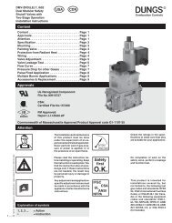
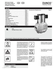
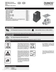
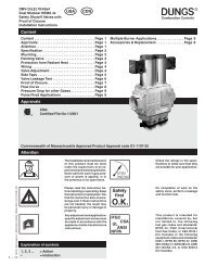
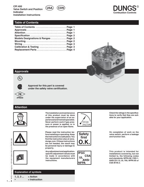
CPI 400<br />
Valve Switch <strong>and</strong> Position<br />
Indicator<br />
Installation Instructions<br />
<strong>USA</strong><br />
CDN<br />
Table of Contents<br />
Table of Contents ........................Page 1<br />
Approvals ...............................Page 1<br />
Attention ................................Page 1<br />
Specification ............................Page 2<br />
Models Designations & Ranges ............Page 2<br />
Mounting. ...............................Page 2<br />
Wiring ..................................Page 3<br />
Calibration & Testing .....................Page 3<br />
Replacement Parts .......................Page 4<br />
Approvals<br />
Approval for this part is covered<br />
under the safety valve certification.<br />
Attention<br />
The installation <strong>and</strong> maintenance<br />
of this product must be done<br />
under the supervision of an experienced<br />
<strong>and</strong> trained specialist.<br />
Never perform work if gas pressure<br />
or power is applied, or in<br />
the presence of an open flame.<br />
[V] [A]<br />
[Hz] [VA]<br />
Check the ratings in the specifications<br />
to verify that they are suitable<br />
for your application.<br />
M/CD • Karl <strong>Dungs</strong> Inc. • CPI 400 • Edition 2013.10 • P/N 261 396<br />
1 … 6<br />
Explanation of symbols<br />
1, 2, 3 ... = Action<br />
• = Instruction<br />
Please read the <strong>instruction</strong> before<br />
installing or operating. Keep<br />
the <strong>instruction</strong> in a safe place. You<br />
find the <strong>instruction</strong> also at www.<br />
dungs.com. If these <strong>instruction</strong>s<br />
are not heeded, the result may<br />
be personal injury or damage to<br />
property.<br />
Any adjustment <strong>and</strong> applicationspecific<br />
adjustment values must<br />
be made in accordance with<br />
the equipment manufacturers<br />
<strong>instruction</strong>s.<br />
Safety<br />
first<br />
O.K.<br />
IFGC<br />
CSA<br />
UL<br />
ANSI<br />
NFPA<br />
On completion of work on the<br />
valve switch, perform a leakage<br />
<strong>and</strong> function test.<br />
This product is intended for<br />
installations covered by, but not<br />
limited to, the following codes<br />
<strong>and</strong> st<strong>and</strong>ards: NFPA 86, CSD-1,<br />
ANSI Z21.13, UL 795, NFPA 85 or<br />
CSA B149.3.
Specification<br />
CPI 400<br />
Closed position indicator CPI 400 visually <strong>and</strong> eletrically indicates when the valve is either in the closed or<br />
open position. Mounts directly to the DMV, SV <strong>and</strong> MVD series valves. When the valve is closed a orange<br />
light is visible, when the valve is open a green light is visible.<br />
SPDT<br />
Ag<br />
[A]<br />
Switch Type<br />
SPDT<br />
Switch Action<br />
Valve open: Green light<br />
Valve closed: Orange light<br />
Contact Rating<br />
10 A res, 8 FLA, 48 LRA @ 120 VAC.<br />
5 A res @ 230 VAC.<br />
1 A max @ 24 VDC <strong>and</strong> 1 A max @<br />
VDC. When used, the 24 VDC/VAC<br />
indicator light consumes 20 mA when<br />
energized<br />
Enclosure<br />
NEMA Type 4<br />
Gas<br />
Gases<br />
Dry, natural gas, propane, butane;<br />
other noncorrosive gases. Suitable<br />
for up to 0.1 % by volume, dry H 2<br />
S<br />
when used with nickel plated brass<br />
adapter. A “dry” gas has a dew point<br />
lower than +15 °F <strong>and</strong> its relative<br />
humidity is less than 60 %.<br />
NEMA<br />
Models Designations & Ranges<br />
Type Description Order No.<br />
CPI 400 Valve Switch 224-253<br />
Mounting<br />
1. The valve must be de-energized <strong>and</strong> the gas supply<br />
shutoff before mounting the CPI.<br />
2. Disconnect all power to the switch before beginning to<br />
prevent electrical shock <strong>and</strong> equipment damage.<br />
Mounting Procedure (reference Fig. 1)<br />
3. IMPORTANT: Before mounting the brass adapter to<br />
the valve or to the CPI 400, use your fingers to verify<br />
that the pin slides freely inside the brass adapter. If<br />
this pin does not slide freely, apply a large enough<br />
force to the appropriate side to free the pin.<br />
4. Using a 5mm hex wrench, remove the plug <strong>and</strong> its o-ring<br />
located at the bottom of the valve.<br />
5. Verify that the brass adapter has a clean o-ring <strong>and</strong> its<br />
threads <strong>and</strong> the groove into which the brass adapter<br />
mounts, are clean <strong>and</strong> in good condition.<br />
6. Mount the brass adapter into the valve.<br />
7. Use a 9/16” (14 mm) open end wrench <strong>and</strong> torque to 44<br />
in-lbs (5Nm), which is about 1/4 turn (after finger tight). DO<br />
NOT overtighten.<br />
8. Mount the CPI switch onto the brass adapter. Push the<br />
CPI housing towards the valve until it stops.<br />
9. Turn/Position the CPI so that the wiring <strong>and</strong> conduit connection<br />
apply the least amount of torque as possible.<br />
O-Ring<br />
Brasss Adapter<br />
Set Screw<br />
Fig. 1<br />
10. Tighten the set screw so that the CPI housing is secured<br />
to the brass adapter.<br />
11. Do not turn the CPI 400 after tightening the set screw;<br />
this may strip the brass adapter. The brass adapter could<br />
loosen <strong>and</strong> the <strong>assembly</strong> may leak.<br />
12. Perform a leak test to verify that no leakage occurs around<br />
the o-ring.<br />
M/CD • Karl <strong>Dungs</strong> Inc. • CPI 400 • Edition 2013.10 • P/N 261 396<br />
2 … 6
Wiring<br />
Required Wiring<br />
• Do not exceed the switches electrical ratings.<br />
• Use 14 or 16 gauge wire for at least 75 ˚C (167 ˚F).<br />
• For NEMA 4 applications, NEMA 4 conduit or wiring methods<br />
must be used.<br />
• Run one wire (the COMMON) to the L1 terminal, one to the<br />
GROUND terminal, one from the terminal 2 “Proof Terminal”<br />
to the Proof of Closure terminal of the Flame Safeguard, <strong>and</strong><br />
one (the NEUTRAL) to L2 on the CPI 400.<br />
NOTE: If equipment neutral is not wired to L2 on the CPI<br />
400, the lights will not properly indicate the valve position.<br />
The ORANGE light should be on when the valve is closed,<br />
The GREEN light should be on when the valve is open (FM<br />
<strong>and</strong> NFPA 86 requirement).<br />
L1<br />
Com<br />
CPI 400 Switch<br />
Orange Lamp<br />
(valve closed)<br />
Green Lamp<br />
(valve opened)<br />
Flame Safeguard<br />
Proof of Closure<br />
terminal<br />
N<br />
L2<br />
N<br />
CPI 400<br />
Made in Germany<br />
Closed Position<br />
Indicator<br />
3<br />
L1; COM<br />
1 Increment<br />
2<br />
Proof<br />
Terminal<br />
Red Wire<br />
1<br />
Yellow Wire<br />
Orange<br />
M/CD • Karl <strong>Dungs</strong> Inc. • CPI 400 • Edition 2013.10 • P/N 261 396<br />
3 … 6<br />
Calibration & Testing<br />
Green<br />
Ground<br />
Fig. 2<br />
The CPI 400 must be calibrated to the specific valve it is<br />
used on. Failing to properly calibrate this switch may lead to<br />
nuisance problems or to an unsafe startup condition.<br />
Calibrating the CPI: (Reference Fig. 2)<br />
1. The CPI must be properly mounted to the valve, <strong>and</strong> the<br />
valve must be closed.<br />
2. Disconnect all power to the CPI 400 before adjusting to<br />
prevent electrical shock <strong>and</strong> equipment damage.<br />
3. Remove clear cover.<br />
4. Turn the adjustment dial counterclockwise until it stops.<br />
5. Then turn the adjustment dial clockwise until the switch<br />
makes. If there is too much noise to hear the switch trip,<br />
proceed to Calibrating the CPI in noisy environments.<br />
6. Note the position of the set point in reference to the white<br />
lines on the scale.<br />
7. Turn the adjustment dial two additional increments clockwise<br />
to the same relative position.<br />
8. Replace clear cover, the CPI is now adjusted.<br />
Calibrating the CPI in noisy environments<br />
1. Verify that there are no stray wires that are potentially a<br />
shock hazard while the dial is being manually adjusted.<br />
2. Apply 120Vac to terminals L1 <strong>and</strong> L2 of the CPI.<br />
3. Turn the adjustment dial counterclockwise until it stops.<br />
The GREEN light should be illuminated.<br />
Do not wire this switch to close a circuit that will<br />
directly power another safety shutoff valve. Doing<br />
so could result in a safety valve being energized<br />
<strong>and</strong> opened rather than emaining closed.<br />
4. Then turn the adjustment dial clockwise until the RED light<br />
illuminates.<br />
5. Note the position of the set point in reference to the white<br />
lines on the scale.<br />
6. Turn the adjustment dial two additional increments clockwise<br />
to the same relative position.<br />
7. Replace clear cover, <strong>and</strong> the CPI is now ready for serivce.<br />
Annual Testing<br />
1. Perform a switch continuity test at least annually to verify<br />
that with the valves de-engerzied, the continuity between<br />
the switch contacts T3 (COM) <strong>and</strong> T2 (Proof Terminal) does<br />
not exceed 0.2 ohms, <strong>and</strong> verify that there is no continuity<br />
between the switch contacts T3 (COM) <strong>and</strong> T1.<br />
2. Then, energize the valve, <strong>and</strong> verify that the continuity<br />
between the switch contacts T3 (COM) <strong>and</strong> T1 does not<br />
exceed 0.2 ohms, <strong>and</strong> then verify that there is no continuity<br />
between the switch contacts T3 (COM) <strong>and</strong> T2.<br />
3. If any above check fails, do not use the CPI <strong>and</strong> contact<br />
DUNGS immediately.
Replacement Parts<br />
Kit Clear plastic cover (1 pcs) 240-837<br />
Kit 120 VAC neon lights (one orange & one green) (1 pcs) 231-420<br />
Kit 24 VAC/VDC neon lights (one red & one green) (1 pcs) 248-183<br />
PG 11 - 1/2” NPT conduit adapter (10 pcs) 231-214<br />
PG 11 - 1/2” NPT conduit adapter (1 pcs) 220-566<br />
Brass adapter (st<strong>and</strong>ard) 224-417<br />
Brass adapter (Ni plated) 224-417B<br />
Karl <strong>Dungs</strong> Inc.<br />
3890 Pheasant Ridge Drive NE<br />
Suite 150<br />
Blaine, MN 55449, U.S.A.<br />
Phone 763 582-1700<br />
Fax 763 582-1799<br />
e-mail info@karldungsusa.com<br />
Internet http://www.dungs.com/usa/<br />
Karl <strong>Dungs</strong> GmbH & Co. KG<br />
P.O. Box 12 29<br />
D-73602 Schorndorf, Germany<br />
Phone +49 (0)7181-804-0<br />
Fax +49 (0)7181-804-166<br />
e-mail info@dungs.com<br />
Internet http://www.dungs.com<br />
M/CD • Karl <strong>Dungs</strong> Inc. • CPI 400 • Edition 2013.10 • P/N 261 396<br />
4 … 6
<strong>USA</strong><br />
CDN<br />
Replacement safety relevant components<br />
Austausch sicherheitsrelevanter Komponenten<br />
It is necessary to replace<br />
safety-relevant components<br />
after they have<br />
reached the end of their<br />
useful life.<br />
DUNGS recommends replacing<br />
such components<br />
according to the following<br />
table:<br />
Es besteht die Notwendigkeit<br />
sicherheitsrelevante<br />
Komponenten nach Erreichen<br />
ihrer Nutzungsdauer<br />
auszutauschen.<br />
DUNGS empfiehlt den<br />
Austausch gemäss folgender<br />
Tabelle:<br />
Valid only for domestic, residential <strong>and</strong> industrial* heating applications.<br />
*Not valid for high performance industrial heat process applications. See page 2<br />
Gültig nur für häusliche Heizungsanlagen<br />
Nicht gültig für Thermprozessanwendungen mit Taktbetrieb<br />
Valve Type<br />
Safety relevant<br />
component<br />
Ventil Typ<br />
Sicherheitsrelevante<br />
Komponente<br />
Recommended replacement after years/cycles:<br />
Depends on the value which will be achieved first<br />
Empfohlener Austausch nach Jahren/Schaltspielen:<br />
Je nachdem welcher Wert zuerst erreicht wird<br />
USEFUL LIFE<br />
[Years]<br />
DUNGS recommends<br />
replacement after:<br />
USEFUL LIFE<br />
[Rated Cycle Life (cycles)]<br />
DUNGS recommends<br />
replacement after:<br />
Max.<br />
Cycle Rate<br />
Max.<br />
Schalthäufigkeit<br />
M/CD • Karl <strong>Dungs</strong> Inc. • CPI 400 • Edition 2013.10 • P/N 261 396<br />
5 … 6<br />
DMV-(D)<br />
SV-(D)<br />
MV(D)/602<br />
DMV/MV/SV:<br />
LE-Ausführungen<br />
(mit Hydraulikbremse)<br />
DMV/MV/SV:<br />
LE-Versions<br />
(with hydraulic brake)<br />
Gasventil mit<br />
DUNGS-Ventilprüfsystem<br />
Gas valve with<br />
DUNGS valve<br />
proving system<br />
NUTZUNGSDAUER<br />
[Jahre]<br />
DUNGS empfiehlt den<br />
Austausch nach:<br />
10 Years<br />
10 Jahre<br />
Austausch nach erkanntem Fehler<br />
Replacement after error detection<br />
Änderungen, die dem technischen Fortschritt dienen, vorbehalten<br />
We reserve the right to make modifications in the course of technical development.<br />
Karl <strong>Dungs</strong> Inc.<br />
3890 Pheasant Ridge Drive NE<br />
Suite 150<br />
Blaine, MN 55449, U.S.A.<br />
Phone 763 582-1700<br />
Fax 763 582-1799<br />
e-mail info@karldungsusa.com<br />
Internet http://www.dungs.com/usa/<br />
NUTZUNGSDAUER<br />
[Schaltspiele (auf/zu)]<br />
DUNGS empfiehlt den<br />
Austausch nach:<br />
1,000,000 cycles 500 /h<br />
500,000 cycles 20 /h<br />
VPS 504*<br />
20 /h<br />
250,000 cycles<br />
VDK 200* 10 Years<br />
15 /h<br />
CPI 400<br />
10 Jahre<br />
1,000,000 cycles @ 1 A <strong>and</strong> 120 VAC<br />
1,000 /h<br />
CPI 401<br />
100,000 cycles @ 10 A <strong>and</strong> 120 VAC<br />
* Valve proving system values shown are expected lifetime. NFPA 86 does not require replacing if the expected life has been exceeded.<br />
Karl <strong>Dungs</strong> GmbH & Co. KG<br />
P.O. Box 12 29<br />
D-73602 Schorndorf, Germany<br />
Phone +49 (0)7181-804-0<br />
Fax +49 (0)7181-804-166<br />
e-mail info@dungs.com<br />
Internet http://www.dungs.com
<strong>USA</strong><br />
CDN<br />
Replacement safety relevant components<br />
Austausch sicherheitsrelevanter Komponenten<br />
It is necessary to replace<br />
safety-relevant components<br />
after they have<br />
reached the end of their<br />
useful life.<br />
DUNGS recommends replacing<br />
such components<br />
according to the following<br />
table:<br />
Es besteht die Notwendigkeit<br />
sicherheitsrelevante<br />
Komponenten nach Erreichen<br />
ihrer Nutzungsdauer<br />
auszutauschen.<br />
DUNGS empfiehlt den<br />
Austausch gemäss folgender<br />
Tabelle:<br />
Valid for high performance industrial heat process applications!<br />
Valve Type<br />
Safety relevant<br />
component<br />
Ventil Typ<br />
Sicherheitsrelevante<br />
Komponente<br />
Recommended replacement after years/cycles:<br />
Depends on the value which will be achieved first<br />
Empfohlener Austausch nach Jahren/Schaltspielen:<br />
Je nachdem welcher Wert zuerst erreicht wird<br />
USEFUL LIFE<br />
[Years]<br />
DUNGS recommends<br />
replacement after:<br />
USEFUL LIFE<br />
[Rated Cycle Life (cycles)]<br />
DUNGS recommends<br />
replacement after:<br />
Max.<br />
Cycle Rate<br />
Max.<br />
Schalthäufigkeit<br />
NUTZUNGSDAUER<br />
[Jahre]<br />
DUNGS empfiehlt den<br />
Austausch nach:<br />
NUTZUNGSDAUER<br />
[Schaltspiele (auf/zu)]<br />
DUNGS empfiehlt den<br />
Austausch nach:<br />
MV ... /602<br />
NPT 1/2 - NPT 2<br />
(no main flow<br />
adjustment)<br />
MVD ... /602<br />
NPT 1/2 - NPT 1<br />
(with main flow<br />
adjustment)<br />
3 Years<br />
3 Jahre<br />
3,000,000 cycles<br />
1,000 /h<br />
MVD ... /602<br />
NPT 11/4 - NPT 3<br />
(with main flow<br />
adjustment)<br />
Conditions<br />
1,000,000 cycles<br />
Clean gas (NG, LNG, LPG): maximum 50 micron gas filter required!<br />
Dry Gas:<br />
■ relative humidity < 60 %<br />
■ dew point of the gas < –14 °F<br />
}"dry"<br />
Not valid for MV(D).../602 valves delivered before 2011/01<br />
Änderungen, die dem technischen Fortschritt dienen, vorbehalten<br />
We reserve the right to make modifications in the course of technical development.<br />
Karl <strong>Dungs</strong> Inc.<br />
3890 Pheasant Ridge Drive NE<br />
Suite 150<br />
Blaine, MN 55449, U.S.A.<br />
Phone 763 582-1700<br />
Fax 763 582-1799<br />
e-mail info@karldungsusa.com<br />
Internet http://www.dungs.com/usa/<br />
Karl <strong>Dungs</strong> GmbH & Co. KG<br />
P.O. Box 12 29<br />
D-73602 Schorndorf, Germany<br />
Phone +49 (0)7181-804-0<br />
Fax +49 (0)7181-804-166<br />
e-mail info@dungs.com<br />
Internet http://www.dungs.com<br />
M/CD • Karl <strong>Dungs</strong> Inc. • CPI 400 • Edition 2013.10 • P/N 261 396<br />
6 … 6