Operation and assembly instruction (USA): 261433 (1.8 MB) - Dungs
Operation and assembly instruction (USA): 261433 (1.8 MB) - Dungs
Operation and assembly instruction (USA): 261433 (1.8 MB) - Dungs

Create successful ePaper yourself
Turn your PDF publications into a flip-book with our unique Google optimized e-Paper software.
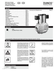
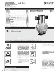
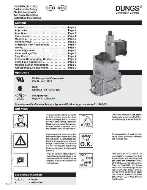
DMV-ZRD(LE) 7../602<br />
Dual Modular Safety<br />
Shutoff Valves with<br />
Two Stage <strong>Operation</strong><br />
Installation Instructions<br />
<strong>USA</strong><br />
CDN<br />
Content<br />
Content .................................Page 1<br />
Approvals ...............................Page 1<br />
Attention ................................Page 1<br />
Specification ............................Page 2<br />
Mounting. ...............................Page 3<br />
Painting Valve ...........................Page 3<br />
Protection from Radiant Heat ..............Page 4<br />
Wiring ..................................Page 4<br />
Valve Adjustment. ........................Page 5<br />
Valve Leakage Test .......................Page 6<br />
Flow Curve ..............................Page 7<br />
Pressure Drop for other Gases .............Page 7<br />
Pulse Fired Application ...................Page 8<br />
Multiple Burner Applications. ..............Page 8<br />
Accessories & Replacement ...............Page 9<br />
Approvals<br />
UL Recognized Component:<br />
File No. MH16727<br />
CSA:<br />
Certified File No.157406<br />
FM Approved:<br />
Report J.I.1Z6A0.AF<br />
Commonwealth of Massachusetts Approved Product Approval code G1-1107-35<br />
Attention<br />
The installation <strong>and</strong> maintenance<br />
of this product must be done<br />
under the supervision of an experienced<br />
<strong>and</strong> trained specialist.<br />
Never perform work if gas pressure<br />
or power is applied, or in<br />
the presence of an open flame.<br />
[V] [A]<br />
[Hz] [VA]<br />
Check the ratings in the specifications<br />
to make sure that they<br />
are suitable for your application.<br />
M/CD • Karl <strong>Dungs</strong> Inc. • DMV-ZRD(LE) 7../602 • Edition 2013.10 • P/N 261 433<br />
1 … 11<br />
Explanation of symbols<br />
1, 2, 3 ... = Action<br />
• = Instruction<br />
Please read the <strong>instruction</strong> before<br />
installing or operating. Keep<br />
the <strong>instruction</strong> in a safe place. You<br />
find the <strong>instruction</strong> also at www.<br />
dungs.com If these <strong>instruction</strong>s<br />
are not heeded, the result may<br />
be personal injury or damage to<br />
property.<br />
Any adjustment <strong>and</strong> applicationspecific<br />
adjustment values must<br />
be made in accordance with the<br />
appliance-/boiler manufacturers<br />
<strong>instruction</strong>s.<br />
Safety<br />
first<br />
O.K.<br />
IFGC<br />
CSA<br />
UL<br />
ANSI<br />
NFPA<br />
On completion of work on the<br />
safety valve, perform a leakage<br />
<strong>and</strong> function test.<br />
This product is intended for<br />
installations covered by, but<br />
not limited to, the following fuel<br />
gas codes <strong>and</strong> st<strong>and</strong>ards: NFPA<br />
54, IFGC (International Fuel Gas<br />
Code), or CSA B149.1 (for Canada)<br />
or the following equipment<br />
codes <strong>and</strong> st<strong>and</strong>ards: CSD-1,<br />
UL 795, NFPA 86, NFPA 37, ANSI<br />
Z83.4/CSA 3.7, ANSI Z83.18, ANSI<br />
Z21.13/CSA 4.9, or CSA B149.3<br />
(for Canada).
Specification<br />
DMV-ZRD/602<br />
Two normally closed safety shutoff valves in one housing. V1 <strong>and</strong> V2 are fast opening, fast closing.<br />
Two stage <strong>and</strong> adjustable max. flow on V2.<br />
DMV-ZRDLE/602 Two normally closed safety shutoff valves in one housing. V1 fast opening, fast closing. V2 is a two<br />
stage, slow opening, fast closing valve. Adjustable max. flow <strong>and</strong> adjustable initial lift with V2.<br />
Max. Operating Pressure<br />
MOP = 7 PSI (500 mbar) UL; FM<br />
MOP = 5 PSI (360 mbar) CSA<br />
°F<br />
+150<br />
Ambient Temperature<br />
-20 °F ... +150 °F<br />
(-30 °C … +65 °C)<br />
[PSI]<br />
0<br />
-40<br />
[V] [A]<br />
[Hz] [VA]<br />
Electrical Ratings Available<br />
110 - 120 VAC / 50 - 60 Hz<br />
Operating time<br />
100 % duty cycle<br />
Power Consumption with all coils<br />
energized<br />
DMV-ZRD(LE) 701: 70 VA<br />
DMV-ZRD(LE) 702: 85 VA<br />
DMV-ZRD(LE): 703: 115 VA<br />
Gas<br />
Gases<br />
Dry, natural gas, propane, butane;<br />
other noncorrosive gases. A “dry” gas<br />
has a dew point lower than +15 °F <strong>and</strong><br />
its relative humidity is less than 60 %.<br />
Materials in contact with Gas<br />
Housing: Aluminium, Steel, free of<br />
nonferrous metals. Sealings on valve<br />
seats: NBR-based rubber.<br />
Classification of Valve V1 <strong>and</strong><br />
V2 Safety Shutoff Valve: UL 429,<br />
FM 7400 & ANSI Z21.21 • CSA 6.5<br />
C/I Valves<br />
Closing Time (Valve 1 & Valve 2)<br />
< 1 s<br />
Opening Time<br />
DMV-ZRD: V1 & V2 < 1 s<br />
DMV-ZRDLE: V1< 1 s;<br />
V2 10 to 20 s at 70 °F<br />
Max. Flow Setting<br />
(DMV-ZRD & DMV-ZRDLE)<br />
Valve 2, Stage 1:
Mounting<br />
Setup<br />
1. Examine the DMV valve for shipping damage.<br />
2. The main gas supply must be shutoff before starting the<br />
installation.<br />
3. The inside of the DMV valve, the flanges, <strong>and</strong> piping must<br />
be clean <strong>and</strong> free of dirt. Remove all dirt <strong>and</strong> debris before<br />
installing the DMV valve. Failure to remove dirt / debris<br />
could result in valve damage or improper performance.<br />
Installation position<br />
Recommended Procedure to Mount the Flanges<br />
1. Unpack the DMV valve <strong>and</strong> remove the socket cap head<br />
screws.<br />
For DMV 701: use 5 mm hex wrench for M6 screws<br />
For DMV 702/703: use 6 mm hex wrench for M8 screws<br />
2. Remove the two white protective plastic covers.<br />
3. Verify the o-rings <strong>and</strong> the grooves are clean <strong>and</strong> in good<br />
condition.<br />
4. Install the DMV valve with the gas flow matching the direction<br />
indicated by the arrows on the casting.<br />
5. Mount the DMV solenoid valve from vertically upright to<br />
horizontal.<br />
6. Clean the mounting surface of the flanges.<br />
7. Mount the flanges to the DMV valve.<br />
8. Tighten the screws in a crisscross pattern. See table for<br />
recommended torque!<br />
Do not overtighten the screws.<br />
Follow the maximum torque values below.<br />
If the flow is not in the same direction of the<br />
arrows, the valves will not operate properly.<br />
19<br />
[Ib-in]<br />
Recommended Torque<br />
System Accessories<br />
M6 M8 Screw Size<br />
Chrome Steel Made in Germany<br />
18<br />
62 lb-in 134 lb-in [Ib-in]<br />
M/CD • Karl <strong>Dungs</strong> Inc. • DMV-ZRD(LE) 7../602 • Edition 2013.10 • P/N 261 433<br />
3 … 11<br />
Recommended Piping Procedure<br />
• Use new, properly reamed <strong>and</strong> threaded pipe free of chips.<br />
• Apply good quality pipe sealant, putting a moderate<br />
amount on the male threads only. If pipe sealant lodges<br />
on the valve seat, it will prevent proper operation. If using<br />
LP gas, use pipe sealant rated for use with LP gas.<br />
19<br />
Chrome Steel Made in Germany<br />
[Ib-in]<br />
18<br />
• On completion of work on the DMV valve, perform a leakage test. (See “Valve Leakage Test”)<br />
Painting Valve<br />
Recommended Torque<br />
for Piping<br />
• It is not recommended that this valve be painted. Painting<br />
covers date codes <strong>and</strong> other labels that identify this valve.<br />
• If the valve needs to be painted, a paint free of volitile organic<br />
componants (VOC’s) must be used. VOC’s can damage<br />
valve o-rings, resulting in external gas leakage over time.<br />
• Do not thread pipe too far. Valve distortion <strong>and</strong>/or malfunction<br />
may result from excess pipe in the valve body.<br />
• Apply counter pressure only a parallel jaw wrench only to<br />
the flats on the flange when connecting to pipe.<br />
• Do not overtighten the pipe. Follow the maximum torque<br />
values listed below.<br />
1/2” 3/4” 1” 1 1/4” 1 1/2” 2” NPT<br />
pipe<br />
375 560 750 875 940 1190 [Ib-in]<br />
• During the painting process, use measures that will allow<br />
the valve’s date code <strong>and</strong> other labeling information to be<br />
legible after the paint is dry.
Protection from Radiant Heat<br />
• Radiant heat must be considered as a heat source that<br />
could result in an ambient temperature higher than the rating<br />
of this valve.<br />
Wiring<br />
Wiring Procedure for V1 <strong>and</strong> V2 stage 1<br />
1. Disconnect all power to the valves before wiring to prevent<br />
electrical shock <strong>and</strong> equipment damage.<br />
2. Attach flexible 1/2” NPT conduit to the DIN connector.<br />
3. Route 14 or 16 guage wire rated for at least 75 ˚C (167 ˚F)<br />
through the conduit <strong>and</strong> the DIN connnector.<br />
4. Connect the wiring to the appropriate screw terminals in<br />
the DIN connector.<br />
5. Plug the DIN connector onto the terminals. Fasten the DIN<br />
connector with the screw supplied.<br />
All wiring must comply with local electrical<br />
codes, ordinances <strong>and</strong> regulations.<br />
Wiring Procedure for V2 stage 2<br />
1. Remove the junction box cover to expose the three terminals<br />
2. The coil can be rotated to accommodate a conduit connection<br />
in any position.<br />
3. Use only one of the knock-outs for connecting conduit to<br />
the junction box. Support the opposite side of the junction<br />
box when removing the knock-out.<br />
• Provide propor shielding to protect against radiant heat.<br />
DIN Connector<br />
screw terminal connections<br />
L1 (AC) Hot<br />
+ (DC)<br />
Valve 2<br />
L2 (AC) Neutral<br />
- (DC)<br />
L1 (AC) Hot<br />
+ (DC)<br />
Valve 1<br />
Ground<br />
4. Run 14 or 16 guage wire rated for 95 °C (200 °F) through<br />
the conduit <strong>and</strong> attach 1/2” NPT conduit to the junction box.<br />
5. Use appropriate tools to connect the conduit fitting to the<br />
junction box.<br />
6. Make electrical connections to the terminals using the wiring<br />
diagram.<br />
7. Replace junction box cover.<br />
GROUND<br />
L2 (N)<br />
L1<br />
HOT<br />
Flat area for support<br />
The second stage coil must be integrated into<br />
the Flame Safeguard shutdown circuitry so that<br />
during any shutdown, voltage to ALL coils is removed;<br />
this will allow both valves to close.<br />
M/CD • Karl <strong>Dungs</strong> Inc. • DMV-ZRD(LE) 7../602 • Edition 2013.10 • P/N 261 433<br />
4 … 11
Valve Adjustment<br />
Flow Setting Valve V2, Stage 1<br />
The valves are supplied with the max. flow adjustment fully<br />
open. To adjust the gas flow proceed as follows:<br />
1. Locate the flow adjustment on top of valve 2 on the DMV-<br />
ZRD (black knob) DMV-ZRDLE (base of the hydraulic<br />
brake). There are two screws, the holding screw is recessed<br />
<strong>and</strong> has a blue sealing compound on it, while the pan head<br />
screw protrudes from the cap.<br />
2. Loosen the pan head screw until you can manually rotate<br />
the flow adjustment dial.<br />
3. Locate the max. flow adjustment dial between the top of the<br />
DMV-ZRD(LE) housing <strong>and</strong> the upper coil for the second<br />
stage.<br />
4. Turn the dial clockwise for less gas or counterclockwise for<br />
more gas.<br />
5. Check the flow at the burner with an orifice or flow meter<br />
until you have achieved the desired flow.<br />
Flow Setting Valve V2, Stage 2<br />
The valves are supplied with the flow adjustment fully open.<br />
To adjust the gas flow proceed as follows:<br />
1. Locate the max. flow adjustment cap on top of valve<br />
2. There are two screws in the cap. The holding screw is<br />
recessed <strong>and</strong> has a blue sealing compound on it, while<br />
the pan head screw protrudes from the cap.<br />
3. Loosen the pan head screw until you can manually rotate<br />
the max. flow adjustment cap for 1 1/2 to 2 turns.<br />
4. Turn the cap clockwise for less gas or counterclockwise<br />
for more gas.<br />
5. Check the flow at the burner with an orifice or flow meter<br />
until you have achieved the desired flow.<br />
6. Tighten the pan head screw on the adjustment cap.<br />
DMV-ZRD<br />
Initial Lift Adjustment<br />
Max Flow Adjustment<br />
Stage 2<br />
Max Flow Adjustment<br />
Stage 1<br />
DMV-ZRDLE<br />
Initial Lift Adjustment (DMV-ZRDLE only)<br />
The initial lift adjustment varies the initial gas flow through the<br />
valve as the valve seat begins to open. This adjustment can<br />
vary the initial flow between 0 % <strong>and</strong> 70 % of the total gas<br />
flow; 0 to 35 % of stroke. All DMV-ZRDLE valves are shipped<br />
from the factory with no initial lift. To adjust the lift proceed<br />
as follows:<br />
1. Unscrew the small black cap on top of the flow adjustment<br />
cap to expose the initial lift adjustment knob.<br />
2. The black cap also serves as tool; turn the cap over <strong>and</strong><br />
insert it into the corresponding slot on the adjustment knob.<br />
3. Turn the knob clockwise for a minimum initial lift or<br />
counterclockwise for a maximum initial lift.<br />
4. Once the desired initial lift has been achieved, reinstall the<br />
black cap.<br />
Test Ports<br />
The G 1/8 ISO 228 taps are available on both sides upstream<br />
V1, between V1 <strong>and</strong> V2, downstream V2, <strong>and</strong> on both flanges.<br />
1 2 3<br />
The G 1/8 test nipple (Ordering Number: 219-008) can be<br />
screwed in any of these pressure tap ports.<br />
Stage II.<br />
DMV-ZRD<br />
p max. = 7 PSI<br />
1V1<br />
V22 3<br />
4 5<br />
1 2 3<br />
M/CD • Karl <strong>Dungs</strong> Inc. • DMV-ZRD(LE) 7../602 • Edition 2013.10 • P/N 261 433<br />
5 … 11<br />
Stage I.<br />
DMV-ZRD<br />
DMV-ZRDLE<br />
DMV-ZRDLE<br />
Do not adjust or remove any screws or bolts<br />
which are sealed with a Red or Blue colored compound.<br />
Doing so will void all approvals <strong>and</strong> warranties.<br />
1<br />
4<br />
p max. = 7 PSI<br />
4 V1 V2 5<br />
1 2 3<br />
5<br />
2<br />
3<br />
5<br />
4<br />
1
Valve Leakage Test<br />
This leak test procedure tests the external sealing <strong>and</strong> valve<br />
seat sealing capabilities of the DMV automatic safety shutoff<br />
valve. Only qualified personnel should perform this test.<br />
It is required that this test be done on the initial system startup,<br />
<strong>and</strong> then repeated at least annually. Possibly more often depending<br />
on the application, environmental parameters, <strong>and</strong><br />
the requirements of the authority having jurisdiction.<br />
Setup<br />
This test requires the following:<br />
• Test nipples installed in the downstream pressure tap port<br />
of each automatic safety shutoff valve to make the required<br />
1/4” hose connection in step 4.<br />
• A transparent glass of water filled at least 1 inch from the<br />
bottom.<br />
• A proper leak test tube. An aluminum or copper 1/4” rigid<br />
tube with a 45˚ cut at the end that is then connected to a<br />
1/4” flexible hose of some convenient length provides for a<br />
more accurate leakage measurement.<br />
However, a 45˚ cut at the end of the 1/4” flexible hose will<br />
suffice, but it will not likely be as accurate as the rigid tube.<br />
• For detecting external leakages, an all purpose liquid leak<br />
detector solution is required.<br />
Leak Test Procedure<br />
Use the illustration below as a reference.<br />
1. With the upstream ball valve open, the downstream ball<br />
valve closed <strong>and</strong> both valves energized, apply an all purpose<br />
liquid leak detector solution to the “External Leakage<br />
Test Areas” indicated in the illustration below, to any<br />
accessories mounted to the safety valve, <strong>and</strong> to all gas<br />
piping <strong>and</strong> gas components downstream the equipment<br />
isolation valve, <strong>and</strong> the inlet <strong>and</strong> outlet gas piping of the<br />
automatic safety shutoff valve. The presence of bubbles<br />
indicates a leak, which needs to be rectified before proceeding.<br />
2. Then, de-energize the burner system <strong>and</strong> verify that both<br />
automatic safety shutoff valves are closed.<br />
3. Close the upstream <strong>and</strong> downstream manual ball valve.<br />
4. Using a screwdriver, slowly open the V1 test nipple (port 2)<br />
by turning it counter clockwise to depressurize the volume<br />
between the two valves, <strong>and</strong> connect the 1/4” flexible hose<br />
to the test nipple.<br />
5. Slowly open the upstream manual ball valve, <strong>and</strong> then provide<br />
for some time to allow potential leakage to charge the<br />
test chamber before measuring the valve seat leakage.<br />
6. Immerse the 1/4 in. tube vertically 1/2 in. (12.7 mm) below<br />
the water surface. If bubbles emerge from the 1/4” tube <strong>and</strong><br />
after the leakage rate has stabilized, count the number of<br />
bubbles appearing during a 10 second period. (See chart<br />
below for allowable leakage rates.)<br />
7. Repeat the same procedure for valve V2 (port 3).<br />
(Energize terminal 2 on the DIN connector to open valve 1)<br />
After completing the above tests proceed as follows:<br />
8. Verify that the downstream manual ball valve is closed,<br />
<strong>and</strong> both automatic safety shutoff valves are de-energized.<br />
9. Remove the flexible hose, <strong>and</strong> close all test nipples.<br />
10. With the upstream manual ball valve open, energize both<br />
automatic safety shutoff valves.<br />
11. Use soapy water to leak test all test nipples to ensure that<br />
there are no leaks.<br />
12. If no leakage is detected, de-energize all automatic safety<br />
shutoff valves, <strong>and</strong> open the downstream manual ball<br />
valve.<br />
If leakage values are exceeded, replace valve<br />
immediately.<br />
Leak Test These Points<br />
1/4” Rigid Tube<br />
1/4”<br />
Flex Hose<br />
G 1/8” Test Nipple<br />
# 219 008<br />
Port 2 Leak Test for V1<br />
Port 3 Leak Test for V2<br />
1/2”<br />
1”<br />
Type Allowable Valve Seat # of Bubbles in 10 s<br />
Leakage* up to 7 PSI inlet Air Natural Gas LP<br />
DMV ZRD(LE) 701/602 239 cc/hr 5 6 4<br />
DMV-ZRD(LE) 702/602 464 cc/hr 9 11 7<br />
DMV-ZRD(LE) 703/602 464 cc/hr 9 11 7<br />
*Based on air <strong>and</strong> test conditions per UL 429 Section 29. (Air or inert gas at a pressure of 1/4 psig <strong>and</strong> also at a pressure of one <strong>and</strong> one-half times<br />
maximum operating pressure differential, but not less than 1/2 psig. This test shall be applied with the valve installed in its intended position.)<br />
Volume of bubble defined in Table 2 of FCI 70-2-1998.<br />
M/CD • Karl <strong>Dungs</strong> Inc. • DMV-ZRD(LE) 7../602 • Edition 2013.10 • P/N 261 433<br />
6 … 11
Flow Curve<br />
Pressure drop (in. W.C.)<br />
1<br />
Based on 60 °F<br />
14.65 psia, dry<br />
Flow (CFH) of natural gas; s.g. 0.65 at 60 °F<br />
M/CD • Karl <strong>Dungs</strong> Inc. • DMV-ZRD(LE) 7../602 • Edition 2013.10 • P/N 261 433<br />
7 … 11<br />
Size valve for at least 2 in. W.C. of pressure drop or more if the inlet pressure in the application is 15 in. W.C.<br />
or less. Otherwise, the difference in flow rate between stage 1 <strong>and</strong> 2 will be note be noticable.<br />
Pressure Drop for other Gases<br />
To determine the pressure drop when using a gas other than<br />
natural gas, use the flow formula below <strong>and</strong> f value located<br />
in the table below to determine the “corrected” flow rate in<br />
CFH through the valve for the other gas used. For example,<br />
Determining equivalent flow through valves using another gas<br />
f =<br />
° °<br />
V gas used<br />
= V Natural gas<br />
x f<br />
Density of Natural gas<br />
Density of gas used<br />
when using propane, divide the volume (CFH) of propane<br />
required for the application by the calculated value f (f = 0.66<br />
for propane). Use this “corrected” flow rate <strong>and</strong> the flow curve<br />
on the next page to determine pressure drop for propane.<br />
Type of gas<br />
Density<br />
[kg/m 3 ]<br />
s.g.<br />
Natural gas 0.81 0.65 1.00<br />
Butane 2.39 1.95 0.58<br />
Propane <strong>1.8</strong>6 1.50 0.66<br />
Air 1.24 1.00 0.80<br />
f
Pulse Fired Application<br />
When using these valves on pulse fired applications, the<br />
following apply:<br />
• Before installing the valve, the inside of all gas piping upstream<br />
to the nearest filter shall be cleaned, <strong>and</strong> that filter<br />
shall have an insert with mesh no larger than 50 micron.<br />
Multiple Burner Applications<br />
On multiple burner applications, the following requirements<br />
apply:<br />
• A manually operated shutoff valve shall be installed downstram<br />
of each individual burner safety shutoff valve.<br />
• The valve shall be installed in the upright position.<br />
• The valve shall be applied within all of its ratings. The type<br />
of gas, the ambient temperature, <strong>and</strong> the cycle rate of the<br />
valve are critical.<br />
• The valve shall be leak tested at least annually.<br />
• After the cycle life has been exceeded, the valve shall be<br />
immedicately replaced.<br />
• The backpressure on the individual burner safety shutoff<br />
valve shall be measured during the commissioning of the<br />
furnace to verify that while all other burners are firing <strong>and</strong><br />
the individual burner safety shutoff valve shall is deenergized,<br />
the backpressure does not exceed 2 PSI. Measuring<br />
the backpressure shall also be repeated during purge <strong>and</strong><br />
post purge. A pressure guage can be used to measure the<br />
backpressure.<br />
M/CD • Karl <strong>Dungs</strong> Inc. • DMV-ZRD(LE) 7../602 • Edition 2013.10 • P/N 261 433<br />
8 … 11
Accessories & Replacement<br />
Coil for<br />
Magnet<br />
Type<br />
Order No. for<br />
120 VAC<br />
DMV-ZRD(LE) 701/602 1111 232-401<br />
DMV-ZRD(LE) 702/602 1211 232-402<br />
DMV-ZRD(LE) 703/602 1212 232-403<br />
Printed Wiring Board (First Stage, Valves One <strong>and</strong> Two)<br />
Order No. for<br />
24 VAC<br />
DMV-ZRD(LE) 701/602 1111 238-803 238-803<br />
DMV-ZRD(LE) 702/602 1211 238-806 238-806<br />
DMV-ZRD(LE) 703/602 1212 238-806 238-806<br />
Accessories/Adapter Order No. Description<br />
Electrical DIN Connector<br />
(Hirschmann)<br />
Electrical DIN Connector<br />
(Burkert)<br />
210-319<br />
246-699<br />
M20 - 1/2 NPT Adapter 240-671<br />
Visual Indicator 217-665A The indicator mounts to the bottom of the valve <strong>and</strong> visually<br />
displays when the valve is open or closed.<br />
Valve Switch CPI 400 224-253A Valve switch with visual indication.<br />
1/4” NPT port 1 or port 2<br />
adapter (reduced port)<br />
1/2” NPT port 2 pilot gas<br />
adapter (reduced port)<br />
225-047<br />
225-043<br />
G 1/8” Test nipple 219-008<br />
Port 3 pressure switch<br />
mounting adapter<br />
214-975<br />
Hydraulic Brake 240-458<br />
Max. Flow Adj. Knob 240-457<br />
M/CD • Karl <strong>Dungs</strong> Inc. • DMV-ZRD(LE) 7../602 • Edition 2013.10 • P/N 261 433<br />
9 … 11<br />
Valve Description Flange NPT<br />
Order No.<br />
Rp<br />
Order No.<br />
O-ring <strong>and</strong><br />
bolt kit<br />
Order No.*<br />
Karl <strong>Dungs</strong> Inc.<br />
3890 Pheasant Ridge Drive NE<br />
Suite 150<br />
Blaine, MN 55449, U.S.A.<br />
Phone 763 582-1700<br />
Fax 763 582-1799<br />
e-mail info@karldungsusa.com<br />
Internet http://www.dungs.com/usa/<br />
FRI mounting<br />
Kit<br />
Order No.**<br />
DMV-ZRD(LE) 701 1/2” 222-371 222-341 224-093 219-967 230-440<br />
DMV-ZRD(LE) 701 3/4” 222-368 222-342 224-093 219-967 230-440<br />
DMV-ZRD(LE) 701 1” 221-999 222-001 224-093 219-967 230-440<br />
DMV-ZRD(LE) 702 & 703 1” 222-369 222-343 224-094 219-968 230-441<br />
DMV-ZRD(LE) 702 & 703 1 1/4” 222-370 222-344 224-094 219-968 230-441<br />
DMV-ZRD(LE) 702 & 703 1 1/2” 222-003 221-884 224-094 219-968 230-441<br />
DMV-ZRD(LE) 702 & 703 2” 221-997 221-926 224-094 219-968 230-441<br />
*Includes two o-rings <strong>and</strong> two sets of bolts (one set of four bolts for each flange).<br />
**Includes four bolts <strong>and</strong> one o-ring.<br />
Integral strainer<br />
<strong>and</strong> Filter<br />
replacement<br />
Karl <strong>Dungs</strong> GmbH & Co. KG<br />
P.O. Box 12 29<br />
D-73602 Schorndorf, Germany<br />
Phone +49 (0)7181-804-0<br />
Fax +49 (0)7181-804-166<br />
e-mail info@dungs.com<br />
Internet http://www.dungs.com
Replacement safety relevant components<br />
Austausch sicherheitsrelevanter Komponenten<br />
It is necessary to replace<br />
safety-relevant components<br />
after they have<br />
reached the end of their<br />
useful life.<br />
DUNGS recommends replacing<br />
such components<br />
according to the following<br />
table:<br />
Es besteht die Notwendigkeit<br />
sicherheitsrelevante<br />
Komponenten nach Erreichen<br />
ihrer Nutzungsdauer<br />
auszutauschen.<br />
DUNGS empfiehlt den<br />
Austausch gemäss folgender<br />
Tabelle:<br />
Valid only for domestic, residential <strong>and</strong> industrial* heating applications.<br />
*Not valid for high performance industrial heat process applications. See page 2<br />
Gültig nur für häusliche Heizungsanlagen<br />
Nicht gültig für Thermprozessanwendungen mit Taktbetrieb<br />
Valve Type<br />
Safety relevant<br />
component<br />
Ventil Typ<br />
Sicherheitsrelevante<br />
Komponente<br />
Recommended replacement after years/cycles:<br />
Depends on the value which will be achieved first<br />
Empfohlener Austausch nach Jahren/Schaltspielen:<br />
Je nachdem welcher Wert zuerst erreicht wird<br />
USEFUL LIFE<br />
[Years]<br />
DUNGS recommends<br />
replacement after:<br />
USEFUL LIFE<br />
[Rated Cycle Life (cycles)]<br />
DUNGS recommends<br />
replacement after:<br />
Max.<br />
Cycle Rate<br />
Max.<br />
Schalthäufigkeit<br />
DMV-(D)<br />
SV-(D)<br />
MV(D)/602<br />
DMV/MV/SV:<br />
LE-Ausführungen<br />
(mit Hydraulikbremse)<br />
DMV/MV/SV:<br />
LE-Versions<br />
(with hydraulic brake)<br />
Gasventil mit<br />
DUNGS-Ventilprüfsystem<br />
Gas valve with<br />
DUNGS valve<br />
proving system<br />
NUTZUNGSDAUER<br />
[Jahre]<br />
DUNGS empfiehlt den<br />
Austausch nach:<br />
10 Years<br />
10 Jahre<br />
Austausch nach erkanntem Fehler<br />
Replacement after error detection<br />
Änderungen, die dem technischen Fortschritt dienen, vorbehalten<br />
We reserve the right to make modifications in the course of technical development.<br />
Karl <strong>Dungs</strong> Inc.<br />
3890 Pheasant Ridge Drive NE<br />
Suite 150<br />
Blaine, MN 55449, U.S.A.<br />
Phone 763 582-1700<br />
Fax 763 582-1799<br />
e-mail info@karldungsusa.com<br />
Internet http://www.dungs.com/usa/<br />
NUTZUNGSDAUER<br />
[Schaltspiele (auf/zu)]<br />
DUNGS empfiehlt den<br />
Austausch nach:<br />
1,000,000 cycles 500 /h<br />
500,000 cycles 20 /h<br />
VPS 504*<br />
20 /h<br />
250,000 cycles<br />
VDK 200* 10 Years<br />
15 /h<br />
CPI 400<br />
10 Jahre<br />
1,000,000 cycles @ 1 A <strong>and</strong> 120 VAC<br />
1,000 /h<br />
CPI 401<br />
100,000 cycles @ 10 A <strong>and</strong> 120 VAC<br />
* Valve proving system values shown are expected lifetime. NFPA 86 does not require replacing if the expected life has been exceeded.<br />
Karl <strong>Dungs</strong> GmbH & Co. KG<br />
P.O. Box 12 29<br />
D-73602 Schorndorf, Germany<br />
Phone +49 (0)7181-804-0<br />
Fax +49 (0)7181-804-166<br />
e-mail info@dungs.com<br />
Internet http://www.dungs.com<br />
M/CD • Karl <strong>Dungs</strong> Inc. • DMV-ZRD(LE) 7../602 • Edition 2013.10 • P/N 261 433<br />
10 … 11
Replacement safety relevant components<br />
Austausch sicherheitsrelevanter Komponenten<br />
It is necessary to replace<br />
safety-relevant components<br />
after they have<br />
reached the end of their<br />
useful life.<br />
DUNGS recommends replacing<br />
such components<br />
according to the following<br />
table:<br />
Es besteht die Notwendigkeit<br />
sicherheitsrelevante<br />
Komponenten nach Erreichen<br />
ihrer Nutzungsdauer<br />
auszutauschen.<br />
DUNGS empfiehlt den<br />
Austausch gemäss folgender<br />
Tabelle:<br />
Valid for high performance industrial heat process applications!<br />
Valve Type<br />
Safety relevant<br />
component<br />
Ventil Typ<br />
Sicherheitsrelevante<br />
Komponente<br />
Recommended replacement after years/cycles:<br />
Depends on the value which will be achieved first<br />
Empfohlener Austausch nach Jahren/Schaltspielen:<br />
Je nachdem welcher Wert zuerst erreicht wird<br />
USEFUL LIFE<br />
[Years]<br />
DUNGS recommends<br />
replacement after:<br />
USEFUL LIFE<br />
[Rated Cycle Life (cycles)]<br />
DUNGS recommends<br />
replacement after:<br />
Max.<br />
Cycle Rate<br />
Max.<br />
Schalthäufigkeit<br />
NUTZUNGSDAUER<br />
[Jahre]<br />
DUNGS empfiehlt den<br />
Austausch nach:<br />
NUTZUNGSDAUER<br />
[Schaltspiele (auf/zu)]<br />
DUNGS empfiehlt den<br />
Austausch nach:<br />
MV ... /602<br />
NPT 1/2 - NPT 2<br />
(no main flow<br />
adjustment)<br />
MVD ... /602<br />
NPT 1/2 - NPT 1<br />
(with main flow<br />
adjustment)<br />
3 Years<br />
3 Jahre<br />
3,000,000 cycles<br />
1,000 /h<br />
MVD ... /602<br />
NPT 11/4 - NPT 3<br />
(with main flow<br />
adjustment)<br />
Conditions<br />
1,000,000 cycles<br />
Clean gas (NG, LNG, LPG): maximum 50 micron gas filter required!<br />
M/CD • Karl <strong>Dungs</strong> Inc. • DMV-ZRD(LE) 7../602 • Edition 2013.10 • P/N 261 433<br />
11 … 11<br />
Dry Gas:<br />
■ relative humidity < 60 %<br />
■ dew point of the gas < –14 °F<br />
Not valid for MV(D).../602 valves delivered before 2011/01<br />
Änderungen, die dem technischen Fortschritt dienen, vorbehalten<br />
We reserve the right to make modifications in the course of technical development.<br />
Karl <strong>Dungs</strong> Inc.<br />
3890 Pheasant Ridge Drive NE<br />
Suite 150<br />
Blaine, MN 55449, U.S.A.<br />
Phone 763 582-1700<br />
Fax 763 582-1799<br />
e-mail info@karldungsusa.com<br />
Internet http://www.dungs.com/usa/<br />
}"dry"<br />
Karl <strong>Dungs</strong> GmbH & Co. KG<br />
P.O. Box 12 29<br />
D-73602 Schorndorf, Germany<br />
Phone +49 (0)7181-804-0<br />
Fax +49 (0)7181-804-166<br />
e-mail info@dungs.com<br />
Internet http://www.dungs.com