Operation and assembly instruction (USA): 261433 (1.8 MB) - Dungs
Operation and assembly instruction (USA): 261433 (1.8 MB) - Dungs
Operation and assembly instruction (USA): 261433 (1.8 MB) - Dungs

You also want an ePaper? Increase the reach of your titles
YUMPU automatically turns print PDFs into web optimized ePapers that Google loves.
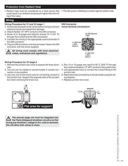
Protection from Radiant Heat<br />
• Radiant heat must be considered as a heat source that<br />
could result in an ambient temperature higher than the rating<br />
of this valve.<br />
Wiring<br />
Wiring Procedure for V1 <strong>and</strong> V2 stage 1<br />
1. Disconnect all power to the valves before wiring to prevent<br />
electrical shock <strong>and</strong> equipment damage.<br />
2. Attach flexible 1/2” NPT conduit to the DIN connector.<br />
3. Route 14 or 16 guage wire rated for at least 75 ˚C (167 ˚F)<br />
through the conduit <strong>and</strong> the DIN connnector.<br />
4. Connect the wiring to the appropriate screw terminals in<br />
the DIN connector.<br />
5. Plug the DIN connector onto the terminals. Fasten the DIN<br />
connector with the screw supplied.<br />
All wiring must comply with local electrical<br />
codes, ordinances <strong>and</strong> regulations.<br />
Wiring Procedure for V2 stage 2<br />
1. Remove the junction box cover to expose the three terminals<br />
2. The coil can be rotated to accommodate a conduit connection<br />
in any position.<br />
3. Use only one of the knock-outs for connecting conduit to<br />
the junction box. Support the opposite side of the junction<br />
box when removing the knock-out.<br />
• Provide propor shielding to protect against radiant heat.<br />
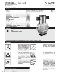
DIN Connector<br />
screw terminal connections<br />
L1 (AC) Hot<br />
+ (DC)<br />
Valve 2<br />
L2 (AC) Neutral<br />
- (DC)<br />
L1 (AC) Hot<br />
+ (DC)<br />
Valve 1<br />
Ground<br />
4. Run 14 or 16 guage wire rated for 95 °C (200 °F) through<br />
the conduit <strong>and</strong> attach 1/2” NPT conduit to the junction box.<br />
5. Use appropriate tools to connect the conduit fitting to the<br />
junction box.<br />
6. Make electrical connections to the terminals using the wiring<br />
diagram.<br />
7. Replace junction box cover.<br />
GROUND<br />
L2 (N)<br />
L1<br />
HOT<br />
Flat area for support<br />
The second stage coil must be integrated into<br />
the Flame Safeguard shutdown circuitry so that<br />
during any shutdown, voltage to ALL coils is removed;<br />
this will allow both valves to close.<br />
M/CD • Karl <strong>Dungs</strong> Inc. • DMV-ZRD(LE) 7../602 • Edition 2013.10 • P/N 261 433<br />
4 … 11