Operation and assembly instruction (USA): 261463 (1.0 MB) - Dungs
Operation and assembly instruction (USA): 261463 (1.0 MB) - Dungs
Operation and assembly instruction (USA): 261463 (1.0 MB) - Dungs

You also want an ePaper? Increase the reach of your titles
YUMPU automatically turns print PDFs into web optimized ePapers that Google loves.
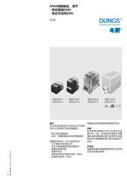
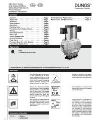
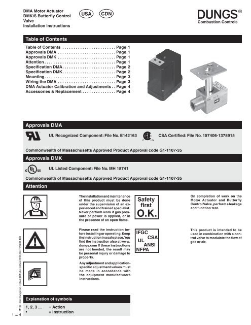
DMA Motor Actuator<br />
DMK/6 Butterfly Control<br />
Valve<br />
Installation Instructions<br />
<strong>USA</strong><br />
CDN<br />
Table of Contents<br />
Table of Contents ....................... Page 1<br />
Approvals DMA ......................... Page 1<br />
Approvals DMK ......................... Page 1<br />
Attention ............................... Page 1<br />
Specification DMA. ...................... Page 2<br />
Specification DMK. ...................... Page 2<br />
Mounting. .............................. Page 3<br />
Wiring the DMA ......................... Page 3<br />
DMA Actuator Calibration <strong>and</strong> Adjustments . Page 4<br />
Accessories & Replacement .............. Page 4<br />
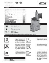
Approvals DMA<br />
UL Recognized Component: File No. E142163 CSA Certified: File No. 157406-1378915<br />
Commonwealth of Massachusetts Approved Product Approval code G1-1107-35<br />
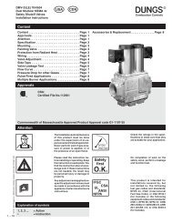
Approvals DMK<br />
UL Listed Component: File No. MH 18741<br />
Commonwealth of Massachusetts Approved Product Approval code G1-1107-35<br />
Attention<br />
The installation <strong>and</strong> maintenance<br />
of this product must be done<br />
under the supervision of an experienced<br />
<strong>and</strong> trained specialist.<br />
Never perform work if gas pressure<br />
or power is applied, or in<br />
the presence of an open flame.<br />
Safety<br />
first<br />
O.K.<br />
On completion of work on the<br />
Motor Actuator <strong>and</strong> Butterfly<br />
Control Valve, perform a leakage<br />
<strong>and</strong> function test.<br />
M/CD • Karl <strong>Dungs</strong> Inc. • DMA; DMK/6 • Edition 2012.06 • P/N 261 463<br />
1 … 4<br />
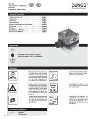
Explanation of symbols<br />
1, 2, 3 ... = Action<br />
• = Instruction<br />
Please read the <strong>instruction</strong> before<br />
installing or operating. Keep<br />
the <strong>instruction</strong> in a safe place. You<br />
find the <strong>instruction</strong> also at www.<br />
dungs.com If these <strong>instruction</strong>s<br />
are not heeded, the result may<br />
be personal injury or damage to<br />
property.<br />
Any adjustment <strong>and</strong> applicationspecific<br />
adjustment values must<br />
be made in accordance with<br />
the equipment manufacturers<br />
<strong>instruction</strong>s.<br />
IFGC<br />
CSA<br />
UL<br />
ANSI<br />
NFPA<br />
This product is intended to be<br />
used in combination with a control<br />
valve to modulate the flow of<br />
gas or air.
Specification DMA<br />
DMA<br />
The actuator drives from 0 to 90 degrees via 4 - 20 mA input signal. It can move in any direction <strong>and</strong> stop<br />
anywhere over the entire 90 degree stroke.<br />
[V] [A]<br />
[Hz] [VA]<br />
Electrical Rating<br />
110 - 120 VAC (+10/-15%) 50 - 60 Hz<br />
Max. Power Rating<br />
2.0 VA Holding, 5.4 VA Operating<br />
°F<br />
+120<br />
+15<br />
0<br />
Ambient Temperature<br />
+15 °F to +120 °F (-10 °C to +50 °C)<br />
19<br />
Chrome Steel Made in Germany<br />
[Ib-in]<br />
18<br />
NEMA<br />
Max. Torque Ratings<br />
Timing Holding Operating<br />
6 12.4 in-lb 5.3 in-lb<br />
12 24.8 in-lb 8.9 in-lb<br />
30 26.5 in-lb 17.7 in-lb<br />
Enclosure Rating<br />
NEMA Type 1/IP 40 enclosure (st<strong>and</strong>ard<br />
with DMA)<br />
NEMA Type 4/IP 65 enclosure availabel<br />
(P/N 240 456)<br />
Position Resolution<br />
0.25 mA resolution; minimum of 1.6°<br />
per step<br />
Max. Contact Rating for Auxiliary<br />
Switch<br />
1.5 Amps at 120 VAC 50/60 Hz<br />
Input Control<br />
4 to 20 mA<br />
Position Feedback or Slave Output<br />
4 to 20 mA; 500 ohm maximum impedance.<br />
Resistence across terminals 8<br />
& 10 is 250 Ohms.<br />
Repeatability: max +/- 2°<br />
Specification DMK<br />
DMK/6<br />
The butterfly control valve actuates from 0 to 90 degrees in either direction; it is not a tight shut-off valve.<br />
Input-side male thread <strong>and</strong> output-side female thread enable <strong>assembly</strong> directly to DUNGS shutoff valves.<br />
[PSI]<br />
Max. Pressure<br />
7 PSI (500 mbar) MH 194167<br />
Max. Differential Pressure for Optimal<br />
Performance<br />
1.5 PSI (100 mbar)<br />
Max. Body Pressure<br />
15 PSI (1000 mbar)<br />
°F<br />
+140<br />
+5<br />
0<br />
Ambient Temperature<br />
+5 °F to +140 °F (-15 °C to +60 °C)<br />
Actuator angle<br />
90 degrees from open to closed<br />
Mounting Position<br />
Multipoised<br />
Gas<br />
Gases<br />
Dry, natural gas, propane, butane;<br />
other noncorrosive gases. Suitable<br />
for up to 0.1 % by volume, dry H 2<br />
S.<br />
A “dry” gas has a dew point lower<br />
than +15 °F <strong>and</strong> its relative humidity<br />
is less than 60 %.<br />
M/CD • Karl <strong>Dungs</strong> Inc. • DMA; DMK/6 • Edition 2012.06 • P/N 261 463<br />
2 … 4
19<br />
Mounting<br />
Mounting DMA to a DMK/6 butterfly valve<br />
1. Remove the clear cover from the DMA.<br />
2. Insert the shaft from the DMA into the linkage of the DMK/6<br />
until the motor is flush on the DMK/6 mounting plate. Snug<br />
the set screw with a 2.5 mm allen wrench. Torque to 15 lb-in.<br />
3. Insert the M5 x 55 mounting bolts (supplied) through the<br />
DMA motor mounting holes. Take care not to break the<br />
plastic covers off of the bolt holes. H<strong>and</strong> tighten the 8 mm<br />
hex nuts that are supplied. Torque the bolts to 45 lb-in.<br />
Mmax.<br />
Mmax.<br />
Fmax.<br />
Fmax.<br />
Mounting the DMK/6 to a shuttoff valve<br />
1. Turn off the gas supply.<br />
2. Refer to the flow direction on the valve housing.<br />
3. Note: Aluminum to Aluminum connection:<br />
Coat inner <strong>and</strong> outer threads with a suitable lubrcant before<br />
sealing the inner <strong>and</strong> outer threads.<br />
4. DO NOT use any part of the DMA or the mounting bracket of<br />
the DMK/6 <strong>assembly</strong> as a lever to tighten! Use appropriate<br />
sized wrench.<br />
5. Tighten connections. Use the chart below for torque<br />
specifications.<br />
6. Perform a complete leak test after installation.<br />
[Ib-in] DMK 707 710 712 715 720<br />
Chrome Steel Made in Germany<br />
18<br />
Max. lb-in 560 750 875 940 1190<br />
M/CD • Karl <strong>Dungs</strong> Inc. • DMA; DMK/6 • Edition 2012.06 • P/N 261 463<br />
3 … 4<br />
Wiring the DMA<br />
1. Remove all power supplies.<br />
2. Use minimum AWG #16 class 1 wiring for all terminals.<br />
3. Remove cover to access the terminal block.<br />
4. Only use the specified terminals.Terminal 8 must be the<br />
+ input <strong>and</strong> terminal 10 must be the - input.<br />
4 - 20 mA Output<br />
Connections<br />
4 - 20 mA Input<br />
Connections<br />
5. The cover has an integrated protective barrier that<br />
physically separates the wiring from the moving adjustment<br />
switches <strong>and</strong> cams. Wiring must be properly routed so that<br />
the cover can be installed.<br />
6. For terminals 8 <strong>and</strong> 10, use properly sheilded wires, that are<br />
grounded on both sides, <strong>and</strong> run through conduit containing<br />
only low voltage (24 V) wiring.<br />
MV auxiliary switch<br />
connections<br />
with motor at 0°<br />
COM<br />
NC<br />
NO<br />
Line<br />
Neutral
DMA Actuator Calibration <strong>and</strong> Adjustments<br />
Calibrating the DMA<br />
Note: The red <strong>and</strong> yellow switches are factory set outside of<br />
the 0 to 90° operating range. Do not change these adjustment<br />
dials until calibration is complete. DO NOT use these switches<br />
in lieu of the calibration.<br />
To Adjust Minimum Position<br />
1. Apply a 4 mA DC input signal.<br />
2. Turn the Y min (Zero) potentiometer (adjusting range 0<br />
to 100 % of stroke) to position the actuator at the desired<br />
minimum position. Turning Y min (Zero) CCW drives the<br />
minimum position towards 0°.<br />
To Adjust Maximum Position<br />
1. Apply 20 mA DC input signal.<br />
2. Turn the Y max (Span) potentiometer (adjusting range 25<br />
to 100 % of stroke) to position the actuator at the desired<br />
maximum position. Turning Y max (Span) CCW drives the<br />
setpoint towards 0°.<br />
Note: Y min (Zero) must be no more than 75 % of Y max<br />
(Span) (reference: 90° = 100 %). E.g. if the maximum<br />
position is set at 85°, the minimum position can be set at<br />
64° maximum. (85° * 0.75 = 64°).<br />
Switch Adjustment<br />
Note: Use the scale under the Red ST1 switch fo field set the<br />
switches. The DMA incorperates two limit switches that limit<br />
the crank shaft from exceeding a set point if the zero or span<br />
potentiometer fails. The DMA also has an SPDT auxiliary<br />
switch. All switches ca be adjusted anywhere over the 90°<br />
stroke.<br />
ST1 Limit Switch (Red): This switch limits the minimum<br />
position at 0° or more. Set the switch at approx. 1° LESS than<br />
the Y Min. setpoint. The small set screw on the side of the red<br />
dial can be used for fine tuning adjustment.<br />
ST2 Limit Switch (Yellow): This switch limits the maximum<br />
position at 90° or less. Set the switch at approx. 1° MORE<br />
than the Y Max. setpoint. The small set screw on the side of<br />
the yellow dial can be used for fine tuning adjustment.<br />
MV Auxiliary Switch (Yellow): Set the switch to trip at the<br />
desired setpoint using the scale under the Red ST1 switch.<br />
When the motor is at 0°, the NC contact 4 <strong>and</strong> 3 opens, <strong>and</strong><br />
the NO contact 4 <strong>and</strong> 2 closes.<br />
ST-2<br />
MV<br />
ST-1<br />
Setpoint Scale<br />
Accessories & Replacement<br />
Description<br />
Order No.<br />
NEMA 4 metal enclosure 240-456<br />
We reserve the right to make modifications in the course of technical development.<br />
Karl <strong>Dungs</strong> Inc.<br />
3890 Pheasant Ridge Drive NE<br />
Suite 150<br />
Blaine, MN 55449, U.S.A.<br />
Karl <strong>Dungs</strong> GmbH & Co. KG<br />
P.O. Box 12 29<br />
D-73602 Schorndorf, Germany<br />
Phone +49 (0)7181-804-0<br />
Phone 763 582-1700<br />
Fax +49 (0)7181-804-166<br />
Fax 763 582-1799<br />
e-mail info@dungs.com<br />
e-mail info@karldungsusa.com Internet http://www.dungs.com<br />
Internet http://www.dungs.com/usa/<br />
M/CD • Karl <strong>Dungs</strong> Inc. • DMA; DMK/6 • Edition 2012.06 • P/N 261 463<br />
4 … 4