Operation and assembly instruction (USA): 261463 (1.0 MB) - Dungs
Operation and assembly instruction (USA): 261463 (1.0 MB) - Dungs
Operation and assembly instruction (USA): 261463 (1.0 MB) - Dungs

Create successful ePaper yourself
Turn your PDF publications into a flip-book with our unique Google optimized e-Paper software.
DMA Actuator Calibration <strong>and</strong> Adjustments<br />
Calibrating the DMA<br />
Note: The red <strong>and</strong> yellow switches are factory set outside of<br />
the 0 to 90° operating range. Do not change these adjustment<br />
dials until calibration is complete. DO NOT use these switches<br />
in lieu of the calibration.<br />
To Adjust Minimum Position<br />
1. Apply a 4 mA DC input signal.<br />
2. Turn the Y min (Zero) potentiometer (adjusting range 0<br />
to 100 % of stroke) to position the actuator at the desired<br />
minimum position. Turning Y min (Zero) CCW drives the<br />
minimum position towards 0°.<br />
To Adjust Maximum Position<br />
1. Apply 20 mA DC input signal.<br />
2. Turn the Y max (Span) potentiometer (adjusting range 25<br />
to 100 % of stroke) to position the actuator at the desired<br />
maximum position. Turning Y max (Span) CCW drives the<br />
setpoint towards 0°.<br />
Note: Y min (Zero) must be no more than 75 % of Y max<br />
(Span) (reference: 90° = 100 %). E.g. if the maximum<br />
position is set at 85°, the minimum position can be set at<br />
64° maximum. (85° * 0.75 = 64°).<br />
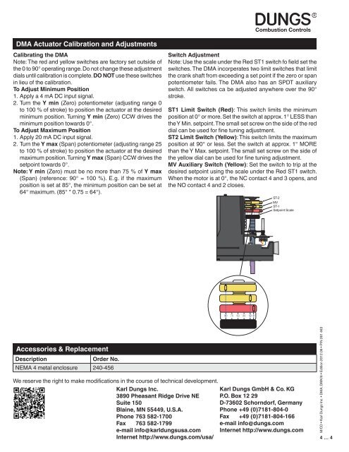
Switch Adjustment<br />
Note: Use the scale under the Red ST1 switch fo field set the<br />
switches. The DMA incorperates two limit switches that limit<br />
the crank shaft from exceeding a set point if the zero or span<br />
potentiometer fails. The DMA also has an SPDT auxiliary<br />
switch. All switches ca be adjusted anywhere over the 90°<br />
stroke.<br />
ST1 Limit Switch (Red): This switch limits the minimum<br />
position at 0° or more. Set the switch at approx. 1° LESS than<br />
the Y Min. setpoint. The small set screw on the side of the red<br />
dial can be used for fine tuning adjustment.<br />
ST2 Limit Switch (Yellow): This switch limits the maximum<br />
position at 90° or less. Set the switch at approx. 1° MORE<br />
than the Y Max. setpoint. The small set screw on the side of<br />
the yellow dial can be used for fine tuning adjustment.<br />
MV Auxiliary Switch (Yellow): Set the switch to trip at the<br />
desired setpoint using the scale under the Red ST1 switch.<br />
When the motor is at 0°, the NC contact 4 <strong>and</strong> 3 opens, <strong>and</strong><br />
the NO contact 4 <strong>and</strong> 2 closes.<br />
ST-2<br />
MV<br />
ST-1<br />
Setpoint Scale<br />
Accessories & Replacement<br />
Description<br />
Order No.<br />
NEMA 4 metal enclosure 240-456<br />
We reserve the right to make modifications in the course of technical development.<br />
Karl <strong>Dungs</strong> Inc.<br />
3890 Pheasant Ridge Drive NE<br />
Suite 150<br />
Blaine, MN 55449, U.S.A.<br />
Karl <strong>Dungs</strong> GmbH & Co. KG<br />
P.O. Box 12 29<br />
D-73602 Schorndorf, Germany<br />
Phone +49 (0)7181-804-0<br />
Phone 763 582-1700<br />
Fax +49 (0)7181-804-166<br />
Fax 763 582-1799<br />
e-mail info@dungs.com<br />
e-mail info@karldungsusa.com Internet http://www.dungs.com<br />
Internet http://www.dungs.com/usa/<br />
M/CD • Karl <strong>Dungs</strong> Inc. • DMA; DMK/6 • Edition 2012.06 • P/N 261 463<br />
4 … 4