3B Scientific - Physics & Engineering Experiments
3B Scientific - Physics & Engineering Experiments
3B Scientific - Physics & Engineering Experiments
You also want an ePaper? Increase the reach of your titles
YUMPU automatically turns print PDFs into web optimized ePapers that Google loves.
UE3040200<br />
ELECTRICITY / INDUCTION<br />
Induction in a Moving Conductor Loop<br />
UE3040200<br />
BASIC PRINCIPLES<br />
The term electromagnetic induction refers to the process whereby an<br />
electric voltage is generated around a conductor loop when the magnetic<br />
flux passing through the loop is changed. Such a change in flux can<br />
result from a change in the magnetic field strength or from movement<br />
of the conductor loop.<br />
EVALUATION<br />
Calculate the velocity from the time t required for the conductor loop<br />
to move completely through the magnetic field and the corresponding<br />
distance L<br />
L<br />
v =<br />
t<br />
To describe the relationships involved, a U-shaped conductor loop with a<br />
moveable crossbar is often considered. The plane of this loop is aligned perpendicular<br />
to a homogeneous magnetic field of flux density B (see Fig. 1).<br />
The magnetic flux through the area limited by the cross-bar is<br />
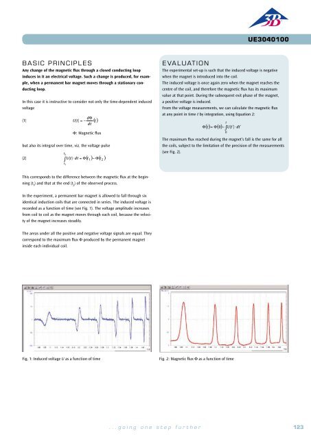
Then draw a graph of the induced voltage U as a function of the velocity<br />
v. The data will be found to lie on a straight line through the origin (see<br />
Fig. 2).<br />
(1)<br />
Φ = B ⋅ a ⋅b<br />
a: Width, b: Length of the loop.<br />
If the cross-bar is moved with a velocity v, the flux changes, since the length<br />
of the loop is changed. The rate of change of the flux is<br />
(2)<br />
dΦ<br />
= B ⋅ a ⋅v<br />
dt<br />
and in the experiment it is observed as a voltage<br />
E X PERIMEN T<br />
PROCEDURE<br />
OBJECTIVE<br />
Measure the induced voltage in a conductor made into a loop as it moves through a magnetic<br />
field<br />
(3)<br />
U = − B ⋅ a ⋅v<br />
which is in the order of microvolts but can be measured using the amplifier<br />
that is recommended as additional equipment.<br />
• Measure the induced voltage as a function<br />
of the velocity of the conductor<br />
A much greater induced voltage is obtained if a conducting loop with multi-<br />
loop.<br />
ple turns on a rigid frame is moved through the magnetic field. When the<br />
• Measure the induced voltage as a<br />
function of the number of turns in the<br />
SUMMARY<br />
The change in magnetic flux that is needed to induce a voltage in a conductor loop can be caused by a<br />
frame is only partly projecting into the magnetic field, the situation is as<br />
shown schematically in Figure 1. The movement of the loop into the magnetic<br />
field results in a change of flux at the following rate<br />
Fig. 1: The change of the magnetic flux through the conducting loop when<br />
its area is altered<br />
conductor loop.<br />
• Compare the sign of the induced volt-<br />
movement of the loop. Such a situation results, for example, when a conductor loop orientated with its<br />
plane perpendicular to a homogeneous magnetic field is moved into the magnetic field or withdrawn<br />
from it at a constant velocity. In the first case the magnetic flux increases at a rate determined by the<br />
(4)<br />
Φ<br />
dt<br />
= B ⋅N<br />
⋅ a ⋅v<br />
d 1<br />
v<br />
age when moving the conductor loop<br />
relevant parameters, whereas in the second case it decreases in a similar way. Therefore the induced<br />
N: Number of turns,<br />
into the field or out of it.<br />
voltages are of opposite signs.<br />
and this can be measured as an induced voltage.<br />
• Compare the sign of the induced voltage<br />
when the direction of motion is<br />
changed.<br />
required apparatus<br />
(5)<br />
U1<br />
= −B<br />
⋅N<br />
⋅ a ⋅<br />
As soon as the conductor loop is completely in the magnetic field, the indu-<br />
• Measure the induced voltage in a<br />
conductor loop with a single turn of<br />
variable area.<br />
Quantity Description Number<br />
1 Induction Apparatus 1000968<br />
1 DC Power Supply 0 – 20 V, 0 – 5 A (230 V, 50/60 Hz) 1003312 or<br />
DC Power Supply 0 – 20 V, 0 – 5 A (115 V, 50/60 Hz) 1003311<br />
ced voltage returns to zero. No further change occurs until the loop begins<br />
to move out of the magnetic field. Now the magnetic flux is decreasing and<br />
the induced voltage is of opposite sign compared with the initial situation.<br />
A change of sign also occurs if the direction of motion of the loop is<br />
reversed.<br />
1 Analogue Multimeter AM50 1003073<br />
1 Set of 15 Safety Experiment Leads, 75 cm 1002843<br />
1 Mechanical Cumulative Stopwatch 1002810<br />
Additionally recommended<br />
In this experiment, the voltage driving an electric motor used to pull the<br />
conductor loop along is varied. This provides a range of different constant<br />
velocities. The direction of rotation of the motor can also be reversed. The<br />
coil provided also has an intermediate tapping point, so that the induced<br />
Fig. 2: Induced voltage as a function of the velocity of the conducting loop<br />
1<br />
1 Measurement Amplifier (230 V, 50/60 Hz) 1001022 or<br />
Measurement Amplifier (115 V, 50/60 Hz) 1001021<br />
voltage can be measured for three different values of N, the number of<br />
turns.<br />
124 <strong>3B</strong> <strong>Scientific</strong>® <strong>Experiments</strong><br />
...going one step further<br />
125


