3B Scientific - Physics & Engineering Experiments
3B Scientific - Physics & Engineering Experiments
3B Scientific - Physics & Engineering Experiments

Create successful ePaper yourself
Turn your PDF publications into a flip-book with our unique Google optimized e-Paper software.
UE4030300<br />
Optics / Wave optics<br />
Fresnel Biprism<br />
UE4030300<br />
Basic PRINCIPLES<br />
In one of his experiments on interference, August Jean Fresnel used a<br />
biprism to induce interference between two beams. He split a diverging<br />
beam of light into two parts by using the biprism to refract them.<br />
This resulted in two split beams which acted as if they were from two<br />
coherent sources and which therefore interfered with each other. By<br />
observing on a screen, he was able to see a series of peaks in the light<br />
intensity with a constant distance between them.<br />
Whether a peak occurs in the intensity or not depends on the difference Δ<br />
in the path travelled by each of the split beams. If the light source is a long<br />
distance L from the screen, the following is true to a good approximation:<br />
(1) Δ = A⋅ x .<br />
L<br />
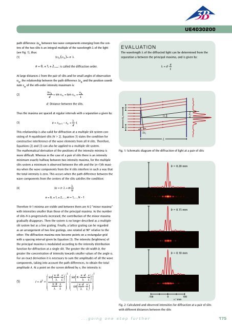
EVALUATION<br />
In this experiment a laser is used as the source of the light. Its beam<br />
is spread out by a lens. The position of the light source is not precisely<br />
known, therefore the object distance a is not known either. It therefore<br />
needs to be calculated from the focal length f of the lens and the easily<br />
measured image distance b using the law for the formation of images:<br />
The following therefore applies:<br />
1<br />
f = 1 a + 1 b<br />
The distances D and L can be measured directly. This means that all the<br />
variables for determining the wavelength using equation (3) are now<br />
known.<br />
A = a⋅ B b = f ⋅B<br />
b − f<br />
Here, x refers to the coordinate of the point observed on the screen which<br />
is perpendicular to the axis of symmetry. A is the distance between the two<br />
virtual light sources, which is yet to be determined Peaks in intensity occur<br />
at the precise points where the difference in the path travelled is a multiple<br />
of the wavelength λ:<br />
S‘2<br />
A<br />
S S‘1<br />
EXPERIMENT<br />
PROCEDURE<br />
• Use a Fresnel biprism to create two<br />
virtual coherent sources of light from<br />
a single point light source.<br />
• Observation of the interference<br />
between the two split beams from the<br />
virtual light sources.<br />
• Determine the wavelength of light from<br />
an He-Ne laser from the separation<br />
between interference bands.<br />
OBJECTIVE<br />
Generating interference between two beams using a Fresnel biprism<br />
SUMMARY<br />
Refraction of a divergent light beam by means of a biprism separates the beam into two parts which,<br />
since they are coherent, will interfere with one another. The wavelength of the light used in the experiment<br />
can be determined using the separation of the virtual light sources and the distance between<br />
adjacent interference bands.<br />
Required Apparatus<br />
Quantity Description Number<br />
(2) Δ n<br />
= n⋅λ , where n = 0, 1, 2, …<br />
A comparison between (1) and (2) shows that the peaks will be at the following<br />
coordinates:<br />
(3)<br />
x n<br />
= n⋅D<br />
They should also be at a constant distance D apart. The following relationship<br />
is also true:<br />
(4) λ = A⋅ D .<br />
L<br />
Equation (4) can be seen as an expression for determining the wavelength λ<br />
of the light being used. It is always applicable for interference between two<br />
beams.<br />
Nevertheless, it is still to be established how the distance between the two<br />
virtual sources A can be measured. This can be assisted by a simple optical<br />
set-up, in which in image of both sources is obtained on the screen with the<br />
help of a converging lens so that the distance B between the images of the<br />
two sources can be measured (see Fig. 2). The following then applies:<br />
L<br />
Fig. 1 : Schematic diagram of light passing through a biprism<br />
A<br />
S‘2<br />
S‘1<br />
X<br />
1 Fresnel Biprism 1008652<br />
1 Prism Table on Stem 1003019<br />
(5)<br />
A = B⋅ a b<br />
1 He-Ne Laser 1003165<br />
a: Object distance, b: Image distance.<br />
1 Achromatic Objective 10x / 0.25 1005408<br />
1 Convex Lens on Stem f =+200 mm 1003025<br />
3 Optical Rider D, 90/50 1002635<br />
L<br />
1 Optical Precision Bench D, 50 cm 1002630<br />
1 Projection Screen 1000608<br />
1 Barrel Foot, 1000 g 1002834<br />
1 Pocket Measuring Tape, 2 m 1002603<br />
Note<br />
Instead of a biprism, a Fresnel mirror (1002649) can also be used to<br />
generate the two virtual light sources. The corresponding list of accessories<br />
can be found under the entry for UE4030320.<br />
b<br />
2<br />
Fig. 2: Ray diagram for obtaining an image of the two virtual sources on<br />
the screen<br />
B<br />
176<br />
<strong>3B</strong> <strong>Scientific</strong>® <strong>Experiments</strong><br />
...going one step further 177