3B Scientific - Physics & Engineering Experiments
3B Scientific - Physics & Engineering Experiments
3B Scientific - Physics & Engineering Experiments

Create successful ePaper yourself
Turn your PDF publications into a flip-book with our unique Google optimized e-Paper software.
UE4030200<br />
OPTICS / WAVE OPTICS<br />
Diffraction by Multiple Slits and Gratings<br />
UE4030200<br />
path difference Δs n<br />
between two wave components emerging from the centres<br />
of the two slits is an integral multiple of the wavelength λ of the light<br />
(see Fig. 1), thus:<br />
(1)<br />
n 0 , ± 1,<br />
± 2,<br />
Δ sn<br />
= ...<br />
( α ) = n⋅λ<br />
n<br />
: is called the diffraction order.<br />
EVALUATION<br />
The wavelength λ of the diffracted light can be determined from the<br />
separation a between the principal maxima, and is given by:<br />
a<br />
λ = d ⋅<br />
L<br />
At large distances L from the pair of slits and for small angles of observation<br />
α n<br />
, the relationship between the path difference Δs n<br />
and the position coordinate<br />
x n<br />
of the nth-order intensity maximum is:<br />
(2)<br />
Δsn<br />
xn<br />
= sin αn<br />
≈ tan αn<br />
=<br />
d<br />
L<br />
d: Distance between the slits.<br />
Thus the maxima are spaced at regular intervals with a separation a given by:<br />
EXPERIMENT<br />
PROCEDURE<br />
• Investigate diffraction at a pair of slits<br />
with different distances between the<br />
slits.<br />
• Investigate diffraction at a pair of slits<br />
with different slit widths.<br />
• Investigate diffraction by multiple slit<br />
systems with different numbers of slits.<br />
• Investigate diffraction by a line grating<br />
and a lattice grating.<br />
OBJECTIVE<br />
Demonstrate the wave nature of light and determine the wavelength<br />
SUMMARY<br />
The diffraction of light by multiple slits or a grating can be described by considering how the individual<br />
components of the coherent wave radiation are superimposed as they emerge from the various slits,<br />
which can each be regarded as a single point of illumination so that the waves superimpose according<br />
to Huygens principle. The interference of the individual waves explains the pattern of bright and<br />
dark bands that is observed beyond the system of slits. If the the separation between the slits and the<br />
distance to the observation screen is known, the wavelength of the light can be calculated from the<br />
distance between any two bright bands.<br />
required apparatus<br />
Quantity Description Number<br />
λ<br />
(3)<br />
a = xn+ 1 − xn<br />
= ⋅L<br />
d<br />
This relationship is also valid for diffraction at a multiple slit system consisting<br />
of N equidistant slits (N > 2). Equation (1) states the condition for<br />
constructive interference of the wave elements from all N slits. Therefore,<br />
Equations (2) and (3) can also be applied to a multiple slit system.<br />
The mathematical derivation of the positions of the intensity minima is<br />
more difficult. Whereas in the case of a pair of slits there is an intensity<br />
minimum exactly halfway between two intensity maxima, for the multiple<br />
slits system a minimum is observed between the nth and the (n+1)th maxima<br />
when the wave components from the N slits interfere in such a way that<br />
the total intensity is zero. This occurs when the path difference between the<br />
wave components from the centres of the slits satisfies the condition:<br />
(4)<br />
λ<br />
Δs<br />
= n⋅λ + m<br />
N<br />
n = 0 , ± 1,<br />
± 2,...<br />
, m = 1,...,<br />
N − 1<br />
Fig. 1: Schematic diagram of the diffraction of light at a pair of slits<br />
b = 0.20 mm<br />
2<br />
1 Laser Diode, Red 1003201<br />
1 Optical Bench K, 1000 mm 1009696<br />
2 Optical Rider K 1000862<br />
1 Clamp K 1008518<br />
1 Holder K for Diode Laser 1000868<br />
1 Diaphragm with 3 Double Slits of Different Widths 1000596<br />
1 Diaphragm with 4 Double Slits of Different Spacings 1000597<br />
1 Diaphragm with 4 Multiple Slits and Gratings 1000598<br />
1 Diaphragm with 3 ruled gratings 1000599<br />
1 Diaphragm with 2 cross gratings 1000601<br />
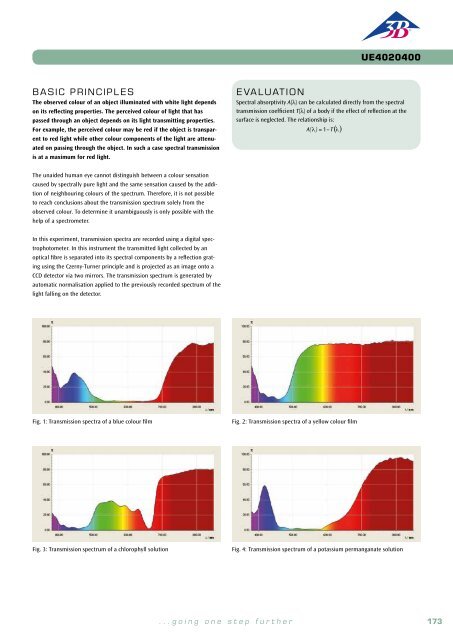
BASIC PRINCIPLES<br />
The diffraction of light by multiple slits or a grating can be described by considering the superimposition<br />
of individual components of the coherent wave radiation, which emerge from each point of<br />
illumination formed by the multiple slits, according to the Huygens principle. The superimposition<br />
leads to constructive or destructive interference in particular directions, and this explains the pattern<br />
of bright and dark bands that is observed beyond the system of slits.<br />
In the space beyond a pair of slits, the light intensity at a particular angle of observation α n<br />
is greatest<br />
when, for each individual wave component coming from the first slit, there exists an exactly similar wave<br />
component from the second slit, and the two interfere constructively. This condition is fulfilled when the<br />
Therefore N-1 minima are visible and between them are N-2 “minor maxima”<br />
with intensities smaller than those of the principal maxima. As the number<br />
of slits N is progressively increased, the contribution of the minor maxima<br />
gradually disappears. Then the system is no longer described as a multiple<br />
slit system but as a line grating. Finally, a lattice grating can be regarded<br />
as an arrangement of two line gratings, one rotated at 90° relative to the<br />
other. The diffraction maxima now become points on a rectangular grid<br />
with a spacing interval given by Equation (3). The intensity (brightness) of<br />
the principal maxima is modulated according to the intensity distribution<br />
function for diffraction at a single slit. The greater the slit width b, the<br />
greater the concentration of intensity towards smaller values of the angle α.<br />
For an exact derivation it is necessary to sum the amplitudes of all the wave<br />
components, taking into account the path differences, to obtain the total<br />
amplitude A. At a point on the screen defined by x, the intensity is:<br />
(5)<br />
2<br />
2<br />
⎛ ⎛ π ⋅b<br />
x ⎞ ⎞ ⎛ ⎛ π ⋅ d x ⎞ ⎞<br />
⎜ sin⎜<br />
⋅ ⎟ ⎟ ⎜ sin⎜N<br />
⋅ ⋅ ⎟ ⎟<br />
2 ⎜ ⎝ λ L ⎠ ⎟ ⎜ ⎝ λ L ⎠<br />
I = A ∝<br />
⎟<br />
⎜<br />
⎟ ⋅<br />
π ⋅b<br />
x ⎜<br />
⎛ π ⋅ d x ⎞<br />
⎟<br />
⎜ ⋅ ⎟ ⎜ sin⎜<br />
⋅ ⎟ ⎟<br />
⎝ λ L ⎠ ⎝ ⎝ λ L ⎠ ⎠<br />
b = 0.15 mm<br />
b = 0.10 mm<br />
Fig. 2: Calculated and observed intensities for diffraction at a pair of slits<br />
with different distances between the slits<br />
174 <strong>3B</strong> <strong>Scientific</strong>® <strong>Experiments</strong><br />
...going one step further<br />
175