3B Scientific - Physics & Engineering Experiments
3B Scientific - Physics & Engineering Experiments
3B Scientific - Physics & Engineering Experiments

Create successful ePaper yourself
Turn your PDF publications into a flip-book with our unique Google optimized e-Paper software.
ELECTRICITY / ELECTRON TUBES<br />
UE3070800 Training Oscilloscope UE3070800<br />
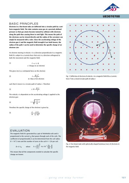
BASIC PRINCIPLES<br />
An important application of thermionic emission in a high vacuum is<br />
the cathode ray oscilloscope, in which the Braun tube is an essential<br />
component. In the form used in the student oscilloscope, the electronoptical<br />
system of the Braun tube, which is visible from the outside, consists<br />
of a thermionic cathode surrounded by a “Wehnelt cylinder” and a<br />
pinhole disc at the anode potential. A proportion of the electrons that<br />
are accelerated towards the anode pass through the pinhole disc and<br />
form a beam, which is observed on the tube’s fluorescent screen as a<br />
green spot of light. Because the tube is filled with neon at a low pressure,<br />
the electron beam is concentrated through collisions with gas<br />
atoms, and is visible as thin threads emitting reddish light. A negative<br />
voltage that is applied to the Wehnelt cylinder also contributes to the<br />
concentration of the beam. Technical oscilloscopes usually have additional<br />
arrangements for post-acceleration (intensification) and focusing<br />
of the beam, but for simplicity and clarity these are not present in the<br />
student oscilloscope.<br />
EVALUATION<br />
If the frequencies are adjusted so that exactly one cycle of the signal is<br />
displayed on the screen, then its frequency matches that of the sawtooth<br />
generator.<br />
Behind the anode, there is a pair of plates with their planes parallel to the<br />
electron beam, which can be connected to a sawtooth generator (see Fig. 1).<br />
EXPERIMENT<br />
PROCEDURE<br />
• Investigating the deflection of an electron<br />
beam in an electric field.<br />
• Investigating the deflection of an electron<br />
beam in a magnetic field.<br />
• Demonstrating the display of signals<br />
on an oscilloscope, using the periodic<br />
signal from a function generator.<br />
• Calibrating the frequency control of<br />
the sawtooth generator.<br />
OBJECTIVE<br />
Study the physical principles of the time-resolved display of electrical signals using an oscilloscope<br />
SUMMARY<br />
The student oscilloscope can be used to study the physical principles of the time-resolved display of<br />
electrical signals on a fluorescent screen. In a Braun tube, a focused electron beam is generated, and<br />
the point at which it falls on the fluorescent screen is observed as a spot of green light. When the electron<br />
beam is deflected by a sawtooth voltage applied between a pair of plates, it moves at a constant<br />
speed from left to right across the screen, then flies back to the starting point. This process is repeated<br />
cyclically at a frequency that can be adjusted. The time-dependent voltage that is to be displayed is<br />
applied to a coil outside the tube, so that the beam is deflected vertically in the magnetic field of the<br />
coil. The time-dependence of the signal is resolved by the simultaneous horizontal motion of the electron<br />
beam and displayed on the fluorescent screen.<br />
The electric field produced by the sawtooth voltage U X (t) deflects the beam<br />
horizontally, so that it moves across the fluorescent screen from left to right<br />
at a constant speed, then flies back to the starting point. This process is<br />
repeated cyclically at a frequency that can be adjusted.<br />
During its left-to-right movement, the electron beam can also be deflected<br />
vertically by a magnetic field, and for this a voltage U Y (t) is applied to the<br />
coils that are external to the tube. If this voltage is time-dependent, the<br />
time-resolved variations are displayed on the screen (see Fig. 2). Such timedependent<br />
voltages might be, for example, the periodic output voltage from<br />
a function generator, or the amplified signals from a microphone.<br />
In the experiment, the periodic signals from a function generator are investigated.<br />
The most useful display is obtained when the sawtooth frequency<br />
is adjusted so that its ratio to that of the function generator is a whole<br />
number.<br />
Fig. 2: Time-resolved display of a periodic signal<br />
required apparatus<br />
Quantity Description Number<br />
1 Training Oscilloscope 1000902<br />
1 DC Power Supply 0 – 500 V (230 V, 50/60 Hz) 1003308 or<br />
DC Power Supply 0 – 500 V (115 V, 50/60 Hz) 1003307<br />
1 Function Generator FG 100 (230 V, 50/60 Hz) 1009957 or<br />
Function Generator FG 100 (115 V, 50/60 Hz) 1009956<br />
1 Set of 15 Safety Experiment Leads, 75 cm 1002843<br />
2<br />
Fig. 1: Schematic diagram of the student oscilloscope, viewed from above<br />
162 <strong>3B</strong> <strong>Scientific</strong>® <strong>Experiments</strong><br />
...going one step further<br />
163