3B Scientific - Physics & Engineering Experiments
3B Scientific - Physics & Engineering Experiments
3B Scientific - Physics & Engineering Experiments

Create successful ePaper yourself
Turn your PDF publications into a flip-book with our unique Google optimized e-Paper software.
UE4010100<br />
Optics / Geometric optics<br />
Lens equation<br />
UE4010100<br />
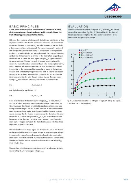
Basic PRINCIPLES<br />
The focal length f of a lens refers to the distance between the main<br />
plane of the lens and its focal point, see Fig.1. This can be determined<br />
using the Bessel method (devised by Friedrich Wilhelm Bessel). This<br />
involves measuring the various separations between the optical components<br />
on the optical bench.<br />
EVALUATION<br />
A formula for the focal length of a thin lens can be derived using the<br />
Bessel method from equation (4) f = a2 − e 2<br />
4a<br />
From Fig.1 and Fig. 2 it can be seen that the following relationship must<br />
apply for a thin lens:<br />
(1)<br />
a = b + g<br />
a: distance between object G and image B<br />
b: distance between lens and image B<br />
g: distance between object G and lens<br />
f<br />
f<br />
By plugging these values into the lens equation<br />
(2)<br />
1<br />
f = 1 b + 1 g<br />
f: focal length of lens<br />
Fig. 1: Schematic showing the definition of focal length for a thin lens<br />
E X PERIMEN T<br />
PROCEDURE<br />
• Determine the two positions of a thin<br />
lens where a sharp image is formed.<br />
• Determine the focal length of a thin<br />
lens.<br />
OBJECTIVE<br />
Determine the focal length of a lens using the Bessel method<br />
SUMMARY<br />
On an optical bench it is possible to set up a light source, a lens, a screen and an object to be imaged<br />
in such a way that a well focussed image appears on the screen. Using the geometric relationships<br />
between the ray paths for a thin lens, it is possible to determine its focal length.<br />
Required Apparatus<br />
the following is obtained:<br />
1<br />
(3)<br />
f = a<br />
a⋅ g − g 2<br />
This corresponds to a quadratic equation with the following pair of solutions:<br />
(4) g 1,2<br />
= a .<br />
2 ± 4 − a⋅ f<br />
A sharp image is obtained for each of the object distances g 1<br />
and g 2<br />
. The<br />
difference e between them allows the focal length to be determined:<br />
(5)<br />
e = g 1<br />
− g 2<br />
= a 2 − 4af<br />
a2<br />
g<br />
f<br />
G<br />
Fig.2: Schematic of ray paths through a lens<br />
a = g + b<br />
b<br />
f<br />
e<br />
B<br />
Quantity Description Number<br />
1 Optical Bench K, 1000 mm 1009696<br />
4 Optical Rider K 1000862<br />
The difference e is the difference between the two lens positions P 1<br />
and P 2<br />
,<br />
which result in a focussed image.<br />
G<br />
P 1 P 2<br />
B<br />
1 Optical Lamp K 1000863<br />
S 1<br />
S 2<br />
1 Transformer 12 V, 25 VA (230 V, 50/60 Hz) 1000866 or<br />
Transformer 12 V, 25 VA (115 V, 50/60 Hz) 1000865<br />
1 Convex Lens K, f = 50 mm 1000869<br />
Fig.3: Schematic showing the two lens positions which result in a well<br />
focussed image on the screen<br />
1 Convex Lens K, f = 100 mm 1010300<br />
1 Clamp K 1008518<br />
1 Set of 4 Image Objects 1000886<br />
1 Projection Screen K, White 1000879<br />
1<br />
170<br />
<strong>3B</strong> <strong>Scientific</strong>® <strong>Experiments</strong><br />
...going one step further 171