3B Scientific - Physics & Engineering Experiments
3B Scientific - Physics & Engineering Experiments
3B Scientific - Physics & Engineering Experiments

You also want an ePaper? Increase the reach of your titles
YUMPU automatically turns print PDFs into web optimized ePapers that Google loves.
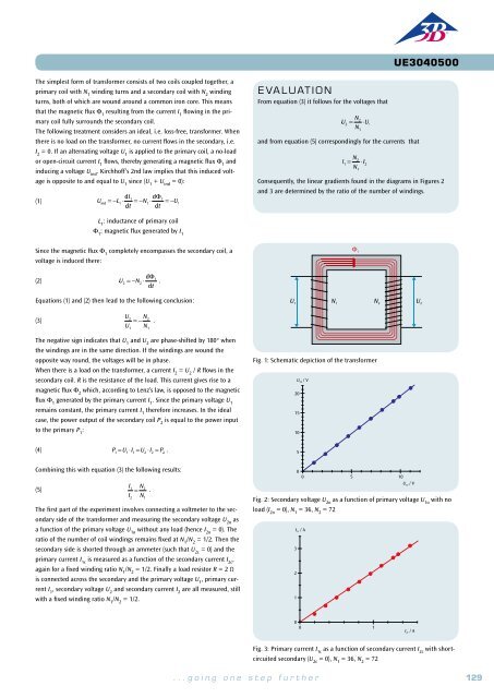
UE3050101<br />
Electricity / DC and AC circuits<br />
Charging and Discharging a Capacitor<br />
UE3050101<br />
BASIC PRINCIPLES<br />
In a DC circuit, current only flows through a capacitor at the point<br />
in time when the power is turned on or off. The current causes the<br />
capacitor to charge up until the voltage across it is equal to the voltage<br />
applied. When the power is switched off, the capacitor will discharge<br />
till the voltage across it drops to zero. A plot of the capacitor voltage<br />
against time can be shown as an exponential curve.<br />
EVALUATION<br />
The fact that the results measured for the length of the half-life over<br />
the various sections of the charging and discharging traces all match<br />
verifies that the curve is of the expected exponential nature, see (1) and<br />
(2). Plots of the half-life periods measured as a function of the resistance<br />
and of the capacitance show that they can fit along a straight line<br />
through the origin in either case, see (3).<br />
(For a DC circuit featuring a capacitance C, resistance R and a DC voltage U 0<br />
,<br />
the following applies when the supply is turned on:<br />
(1)<br />
U(t ) = U 0 ⋅ (1− e<br />
− t⋅ln2<br />
T 1/2<br />
)<br />
T 1/2 / ms<br />
1<br />
The following applies when the power supply is switched off:<br />
(2)<br />
− t⋅ln2<br />
T 1/2<br />
U(t ) = U 0 ⋅ e<br />
EXPERIMENT<br />
PROCEDURE<br />
• Measure the voltage across a capacitor<br />
as it charges and discharges when the<br />
DC supply voltage to a circuit is turned<br />
on and off.<br />
• Determine the half-life period for<br />
charging and discharging.<br />
• Investigate how the half-life period<br />
depends on the capacitance and the<br />
resistance.<br />
OBJECTIVE<br />
Investigation of how the voltage across a capacitor changes over time when the capacitor is<br />
charging or discharging<br />
SUMMARY<br />
In a DC circuit, current only flows through a capacitor at the point in time when the power is turned<br />
on or off. The current causes the capacitor to charge up until the voltage across it is equal to the voltage<br />
applied. When the power is switched off, the capacitor will discharge till the voltage across it drops<br />
to zero. A plot of the capacitor voltage against time can be shown as an exponential curve, i.e. the<br />
voltage drops by half in the space of a fixed period T 1/2<br />
called the half-life. The same period elapses<br />
when the voltage drops from a half to a quarter and from a quarter to an eighth. The half-life period<br />
is proportional to the capacitance and the resistance through which the capacitor discharges.<br />
where<br />
(3)<br />
T 1/2<br />
= ln2 ⋅R ⋅C<br />
T 1/2<br />
is the half-life period, i.e. the voltage across the a discharging capacitor<br />
will halve within a time T 1/2<br />
. The same period elapses when the voltage<br />
drops from a half to a quarter and from a quarter to an eighth.<br />
These aspects will be investigated in the experiment. How the capacitor<br />
voltage changes over time is recorded using a storage oscilloscope. Since<br />
the DC voltage U 0<br />
is set to 8 V, it is easy to read off a half, a quarter and an<br />
eighth of that value.<br />
0<br />
0 1 2 3<br />
R / kÙ<br />
Fig. 2: Half-life T 1/2<br />
as a function of resistance R<br />
T 1/2 / ms<br />
1<br />
Required Apparatus<br />
Quantity Description Number<br />
1 Plug-In Board for Components 1012902<br />
0<br />
0 1 2<br />
C / ìF<br />
1 Resistor 470 Ω, 2 W, P2W19 1012914<br />
1 Resistor 1 kΩ, 2 W, P2W19 1012916<br />
Fig. 3: Half-life T 1/2<br />
as a function of capacitance C<br />
1 Resistor 2.2 kΩ, 2 W, P2W19 1012918<br />
3 Capacitor 1 µF, 100 V, P2W19 1012955<br />
T 1/2 / ms<br />
1<br />
1 Function Generator FG 100 (230 V, 50/60 Hz) 1009957 or<br />
Function Generator FG 100 (115 V, 50/60 Hz) 1009956<br />
1 USB Oscilloscope 2x50 MHz 1017264<br />
2 HF Patch Cord, BNC/4 mm Plug 1002748<br />
Fig. 1: Traces of voltage across a capacitor while charging and discharging<br />
recorded with an oscilloscope<br />
1 Set of 15 Experiment Leads, 75 cm 1 mm² 1002840<br />
1 Set of 10 Jumpers, P2W19 1012985<br />
1<br />
0<br />
0 1<br />
RC / ms<br />
Fig. 4: Half-life T 1/2<br />
as a function of the product of R*C<br />
130 <strong>3B</strong> <strong>Scientific</strong>® <strong>Experiments</strong> ...going one step further 131