3B Scientific - Physics & Engineering Experiments
3B Scientific - Physics & Engineering Experiments
3B Scientific - Physics & Engineering Experiments

Create successful ePaper yourself
Turn your PDF publications into a flip-book with our unique Google optimized e-Paper software.
Optics / Wave optics<br />
UE4030350<br />
Newton’s rings<br />
UE4030350<br />
E X PERIMEN T<br />
PROCEDURE<br />
• Observe Newton’s rings with monochromatic<br />
light transmitted through the<br />
apparatus.<br />
• Measure the radius of the rings and<br />
determine the radius of curvature of<br />
the spherical body.<br />
• Determine by how much the set up is<br />
deformed by the sphere pressing down<br />
on the plate.<br />
OBJECTIVE<br />
Observe Newton’s rings in monochromatic light<br />
SUMMARY<br />
Newton’s rings are generated by a set-up involving a flat glass plate and a spherical body with a large<br />
radius of curvature. If parallel monochromatic light is incident on the set-up from an angle normal to<br />
the apparatus, alternating light and dark concentric rings are generated, centred on the point where<br />
the surfaces meet. In this experiment Newton’s rings are investigated using monochromatic light transmitted<br />
through the apparatus. The radius of curvature R of the spherical body can be determined from<br />
the radii r of the interference rings as long as the wavelength λ is known.<br />
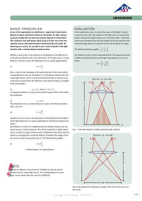
Basic PRINCIPLES<br />
Newton’s rings are a phenomenon which can be viewed on a daily basis.<br />
They arise due to interference in light reflecting from the upper and lower<br />
boundaries of an air gap between two very nearly parallel surfaces. In<br />
white light, this produces colourful interference, since the condition for<br />
a maximum in the interference is dependent on the wavelength.<br />
In order to deliberately generate Newton’s rings, a set-up is used which<br />
involves a flat glass plate and a spherical body with a large radius of<br />
curvature. The spherical body touches the flat glass plate in such a way<br />
that an air gap results. If parallel monochromatic light is incident on the<br />
set-up from an angle normal to the apparatus, alternating light and dark<br />
concentric rings are generated, centred on the point where the surfaces<br />
meet. The darker rings are caused by destructive interference while the light<br />
ones result from constructive interference. The light waves reflected from<br />
the boundary between the spherical body and the air interfere with ones<br />
reflected from the boundary between the flat plate and the air. The interference<br />
rings can be viewed in both reflected and transmitted light. With<br />
transmission, though, the interference is always constructive at the centre,<br />
regardless of the wavelength of the incident light.<br />
The separation between the interference rings is not constant. The thickness<br />
d of the air gap varies in proportion to the distance r from the point of<br />
contact between body and plate. The following can be seen from Fig. 1:<br />
( ) 2<br />
(1)<br />
R 2 = r 2 + R - d<br />
R: radius of curvature<br />
This means that when the thickness d is small, the following applies for the<br />
bright interference rings:<br />
(2) d = r 2<br />
,<br />
2⋅R = ( n− 1)⋅<br />
λ 2<br />
Therefore the radii of the bright rings are given by<br />
(3) r 2 = (n− 1)⋅R⋅λ .<br />
EVALUATION<br />
To determine the radius r, an average is taken of the measured radius<br />
values for the crossover point to the left and right. The magnification<br />
due to the lens is also taken into account.<br />
Values for r 2 are then plotted as a function of n-1, whereby the measurements<br />
lie on straight lines of gradients a = R⋅λ which cross the axes<br />
at b = 2⋅R⋅d 0<br />
. Since the wavelengths are known, it is possible to calculate<br />
the radius of curvature R. This is approximately 45 m. The flattening<br />
d 0<br />
of the sphere due to it pressing down on the plate is less than<br />
one micrometer.<br />
r² / mm²<br />
200<br />
R-d<br />
Fig. 1: Schematic illustration of the air gap between the convex lens and<br />
the flat plate<br />
r<br />
R<br />
= 578 nm<br />
d<br />
= 546 nm<br />
Required Apparatus<br />
Quantity Description Number<br />
It may be seen that the spherical body is slightly deformed at the point<br />
of contact. By rearranging equation (2) an approximation of this can be<br />
derived from the following expression:<br />
100<br />
1 Optical Precision Bench D, 100 cm 1002628<br />
6 Optical Rider D, 90/50 1002635<br />
(4) d = r 2<br />
for<br />
2⋅R − d 0<br />
<br />
r 2 ≥ 2⋅R⋅d 0<br />
<br />
0<br />
0 5 10<br />
n-1<br />
1 Control Unit for Spectrum Lamps (230 V, 50/60 Hz) 1003196 or<br />
Control Unit for Spectrum Lamps (115 V, 50/60 Hz) 1003195<br />
1 Spectral Lamp Hg 100 1003545<br />
Therefore the radii of the bright rings are now given by:<br />
(5)<br />
r i 2 = (n− 1)⋅R⋅λ + 2⋅R⋅d 0<br />
<br />
Fig. 2: Relationship between radii r 2 of bright interference rings and their<br />
number in sequence n<br />
1 Convex Lens on Stem f =+50 mm 1003022<br />
1 Convex Lens on Stem f =+100 mm 1003023<br />
1 Iris on Stem 1003017<br />
1 Glass Inset for Newton’s Rings <strong>Experiments</strong> 1008669<br />
This experiment investigates Newton’s rings using transmitted light from<br />
a mercury lamp which has been rendered monochromatic with the aid of<br />
interference filters. The interference pattern is focussed onto the screen<br />
with the help of an objective lens.<br />
1 Component Holder 1003203<br />
1 Interference Filter 578 nm 1008672<br />
1 Interference Filter 546 nm 1008670<br />
2<br />
1 Projection Screen 1000608<br />
1 Barrel Foot, 1000 g 1002834<br />
1 Pocket Measuring Tape, 2 m 1002603<br />
Fig. 3: Newton’s rings in yellow light<br />
178 <strong>3B</strong> <strong>Scientific</strong>® <strong>Experiments</strong><br />
...going one step further<br />
179