3B Scientific - Physics & Engineering Experiments
3B Scientific - Physics & Engineering Experiments
3B Scientific - Physics & Engineering Experiments

You also want an ePaper? Increase the reach of your titles
YUMPU automatically turns print PDFs into web optimized ePapers that Google loves.
UE3050301<br />
Electricity / DC and AC<br />
AC Resistance<br />
UE3050301<br />
The complex resistance (impedance) of a capacitor with capacitance C in a<br />
circuit with an alternating current of frequency f is as follows:<br />
1<br />
(1) X C<br />
= ,<br />
i ⋅ω ⋅C<br />
Angular frequency<br />
ω = 2π⋅ f<br />
Therefore series circuits containing a capacitor and an ohmic resistor R will<br />
have the following overall resistance:<br />
EVALUATION<br />
The magnitude of the overall resistance (impedance) Z 0<br />
= U 0<br />
is displayed<br />
I 0 1<br />
as a function of frequency f or of the capacitive resistance XC = .<br />
2π⋅ f ⋅C<br />
At low frequencies the resistance of the series circuit corresponds to the<br />
capacitive resistance and that of the parallel circuit corresponds to the<br />
ohmic resistance. The phase shift is between 0° and 90° and equals 45°<br />
if the ohmic and capacitive resistance values are the same.<br />
1<br />
(2) Z S<br />
= ,<br />
i ⋅ω ⋅C + R<br />
A parallel circuit can be assigned the following overall resistance<br />
Z / <br />
10000<br />
(3)<br />
Z P<br />
=<br />
1<br />
1000<br />
E X PERIMEN T<br />
PROCEDURE<br />
OBJECTIVE<br />
Determine the AC resistance in a circuit with capacitive and resistive loads<br />
i ⋅ω ⋅C + 1 R<br />
The usual way of expressing this is as follows:<br />
100<br />
• Determine the amplitude and phase of<br />
the overall resistance as a function of<br />
frequency for a series circuit.<br />
• Determine the amplitude and phase of<br />
the overall resistance as a function of<br />
frequency for a parallel circuit.<br />
SUMMARY<br />
In AC circuits, not only ohmic resistance needs to be taken into account but also the resistance due to<br />
capacitive loads. The combination of the two may be connected in series or parallel. This has an effect<br />
on both the amplitudes and phase of the current and voltage. In the experiment, this will be investigated<br />
using an oscilloscope and a function generator supplying alternating current with frequencies<br />
between 50 and 2000 Hz.<br />
(4)<br />
This becomes<br />
(5)<br />
where<br />
and<br />
Z S<br />
=<br />
Z = Z 0<br />
⋅exp(i ⋅ϕ)<br />
1+ ( ω ⋅C ⋅R )2<br />
⋅exp( i ⋅ϕ S )<br />
ω ⋅C<br />
1<br />
tanϕ S<br />
= −<br />
ω ⋅C ⋅R<br />
(6)<br />
Z P<br />
=<br />
R<br />
1+ ( ω ⋅C ⋅R) ( i ⋅ϕ 2 P )<br />
where tanϕ P<br />
= −ω ⋅C ⋅R .<br />
1<br />
10 100<br />
Fig. 3: Overall resistance for series circuit<br />
<br />
90°<br />
60°<br />
30°<br />
1000<br />
10000<br />
X C<br />
/ <br />
Required Apparatus<br />
Quantity Description Number<br />
1 Plug-In Board for Components 1012902<br />
1 Resistor 1 Ω, 2 W, P2W19 1012903<br />
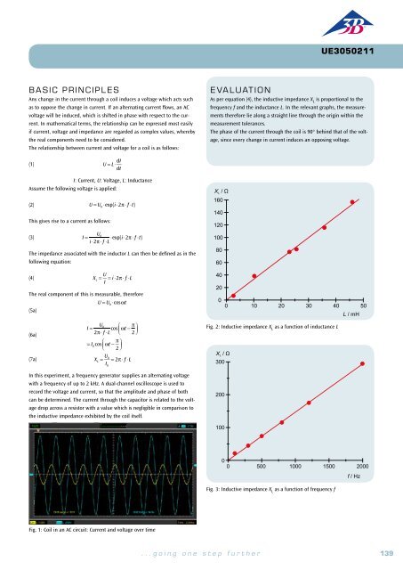
In this experiment a function generator supplies an AC voltage with a frequency<br />
f, which is adjusted between 50 and 2000 Hz. Voltage U and current I<br />
are recorded on an oscilloscope, whereby, I is displayed in the form of the<br />
voltage drop across a small auxiliary resistor. This allows the real components<br />
of the voltage across the relevant resistance Z.<br />
0°<br />
1<br />
10<br />
100<br />
Fig. 4: Phase shift for series circuit<br />
Z / <br />
1000<br />
1000<br />
10000<br />
X C<br />
/ <br />
1 Resistor 100 Ω, 2 W, P2W19 1012910<br />
1 Capacitor 10 µF, 35 V, P2W19 1012957<br />
(7)<br />
U = U 0<br />
⋅exp(i ⋅ω ⋅t)<br />
The resulting current is as follows:<br />
100<br />
1 Capacitor 1 µF, 100 V, P2W19 1012955<br />
1 Capacitor 0.1 µF, 100 V, P2W19 1012953<br />
1 Function Generator FG 100 (230 V, 50/60 Hz) 1009957 or<br />
(8) I = U 0<br />
⋅exp(i ⋅( ω ⋅t − ϕ))<br />
.<br />
Z 0<br />
= I 0<br />
⋅exp(i ⋅( ω ⋅t − ϕ))<br />
10<br />
Function Generator FG 100 (115 V, 50/60 Hz) 1009956<br />
1 USB Oscilloscope 2x50 MHz 1017264<br />
The amplitudes I 0 and U 0 , plus the phase shift ϕ can all be read from the<br />
oscilloscope.<br />
1<br />
1<br />
10<br />
100<br />
1000<br />
10000<br />
X C<br />
/ <br />
2 HF Patch Cord, BNC/4 mm Plug 1002748<br />
Fig. 5: Overall resistance for parallel circuit<br />
1 Set of 15 Experiment Leads, 75 cm 1 mm² 1002840<br />
R<br />
<br />
90°<br />
2<br />
basic PRINCIPLES<br />
In AC circuits, it is common to use complex numbers to describe the resistance in circuits with<br />
capacitors because this actually makes calculation easier. This is because not only the amplitude<br />
of the current and voltage is a factor, but also the phase relationships between the two need to<br />
be taken into account (this complex resistance is usually called impedance). Series and parallel<br />
circuits with both ohmic and capacitive resistance can then be described quite easily, although<br />
in each case, only the real component is measurable).<br />
U(t)<br />
C<br />
R m<br />
I(t)·R m<br />
Fig. 1: Measurement set-up for<br />
series circuit<br />
U(t)<br />
U(t)<br />
R<br />
R m<br />
C<br />
I(t)·R m<br />
Fig. 2: Measurement set-up for<br />
parallel circuit<br />
U(t)<br />
60°<br />
30°<br />
0°<br />
10<br />
100<br />
Fig. 6: Phase shift for parallel circuit<br />
1000<br />
10000<br />
X C / <br />
140<br />
<strong>3B</strong> <strong>Scientific</strong>® <strong>Experiments</strong><br />
...going one step further 141