3B Scientific - Physics & Engineering Experiments
3B Scientific - Physics & Engineering Experiments
3B Scientific - Physics & Engineering Experiments

You also want an ePaper? Increase the reach of your titles
YUMPU automatically turns print PDFs into web optimized ePapers that Google loves.
UE3050211<br />
Electricity / DC and AC circuits<br />
Impedance of a Coil in an AC Circuit<br />
UE3050211<br />
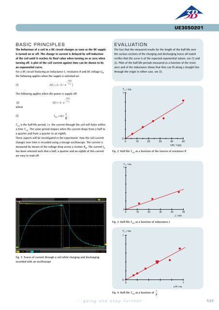
BASIC PRINCIPLES<br />
Any change in the current through a coil induces a voltage which acts such<br />
as to oppose the change in current. If an alternating current flows, an AC<br />
voltage will be induced, which is shifted in phase with respect to the current.<br />
In mathematical terms, the relationship can be expressed most easily<br />
if current, voltage and impedance are regarded as complex values, whereby<br />
the real components need to be considered.<br />
The relationship between current and voltage for a coil is as follows:<br />
EVALUATION<br />
As per equation (4), the inductive impedance X L<br />
is proportional to the<br />
frequency f and the inductance L. In the relevant graphs, the measurements<br />
therefore lie along a straight line through the origin within the<br />
measurement tolerances.<br />
The phase of the current through the coil is 90° behind that of the voltage,<br />
since every change in current induces an opposing voltage.<br />
(1)<br />
U = L⋅ dI<br />
dt<br />
I: Current, U: Voltage, L: Inductance<br />
Assume the following voltage is applied:<br />
(2)<br />
This gives rise to a current as follows:<br />
U = U 0<br />
⋅exp(i ⋅2π⋅ f ⋅t)<br />
X<br />
L<br />
/ Ù<br />
160<br />
140<br />
120<br />
EXPERIMENT<br />
PROCEDURE<br />
OBJECTIVE<br />
Determine inductive impedance as a function of inductance and frequency<br />
(3)<br />
U 0<br />
I = ⋅exp(i ⋅2π⋅ f ⋅t)<br />
i ⋅2π⋅ f ⋅L<br />
The impedance associated with the inductor L can then be defined as in the<br />
following equation:<br />
100<br />
80<br />
60<br />
• Determine the amplitude and phase<br />
of inductive impedance as a function<br />
of the inductance.<br />
• Determine the amplitude and phase<br />
of inductive impedance as a function<br />
of the frequency<br />
SUMMARY<br />
Any change in the current through a coil induces a voltage. If an alternating current flows, an AC voltage<br />
will be induced, which is shifted in phase with respect to the current. In mathematical terms, the<br />
relationship can be expressed most easily if current, voltage and impedance are regarded as complex<br />
values, whereby the real components need to be considered. In this experiment, a frequency generator<br />
supplies an alternating voltage with a frequency of up to 2 kHz. A dual-channel oscilloscope is used to<br />
record the voltage and current, so that the amplitude and phase of both can be determined. The current<br />
through the coil is given by the voltage drop across a resistor with a value which is negligible in<br />
comparison to the inductive impedance exhibited by the coil itself.<br />
Required Apparatus<br />
Quantity Description Number<br />
1 Plug-In Board for Components 1012902<br />
(4)<br />
X L<br />
= U = i ⋅2π⋅ f ⋅L<br />
I<br />
The real component of this is measurable, therefore<br />
U = U 0<br />
⋅cosωt<br />
(5a)<br />
U 0<br />
I =<br />
(6a)<br />
2π⋅ f ⋅L cos ⎛<br />
ωt − π ⎞<br />
⎝<br />
⎜<br />
2 ⎠<br />
⎟<br />
= I 0<br />
cos<br />
⎛<br />
ωt − π ⎞<br />
⎝<br />
⎜<br />
2 ⎠<br />
⎟<br />
(7a)<br />
X L<br />
= U 0<br />
= 2π⋅ f ⋅L<br />
I 0<br />
In this experiment, a frequency generator supplies an alternating voltage<br />
with a frequency of up to 2 kHz. A dual-channel oscilloscope is used to<br />
record the voltage and current, so that the amplitude and phase of both<br />
can be determined. The current through the capacitor is related to the voltage<br />
drop across a resistor with a value which is negligible in comparison to<br />
the inductive impedance exhibited by the coil itself.<br />
40<br />
20<br />
0<br />
X L / Ù<br />
300<br />
200<br />
100<br />
0 10 20 30 40 50<br />
Fig. 2: Inductive impedance X L<br />
as a function of inductance L<br />
L / mH<br />
2 Coil S with 1200 Taps 1001002<br />
1 Resistor 10 Ω, 2 W, P2W19 1012904<br />
1 Function Generator FG 100 (230 V, 50/60 Hz) 1009957 or<br />
Function Generator FG 100 (115 V, 50/60 Hz) 1009956<br />
0<br />
0 500 1000 1500 2000<br />
1 USB Oscilloscope 2x50 MHz 1017264<br />
f / Hz<br />
2 HF Patch Cord, BNC/4 mm Plug 1002748<br />
1 Set of 15 Experiment Leads, 75 cm 1 mm² 1002840<br />
Fig. 3: Inductive impedance X L<br />
as a function of frequency f<br />
2<br />
Fig. 1: Coil in an AC circuit: Current and voltage over time<br />
138 <strong>3B</strong> <strong>Scientific</strong>® <strong>Experiments</strong> ...going one step further 139