Whole report - STUK
Whole report - STUK
Whole report - STUK

You also want an ePaper? Increase the reach of your titles
YUMPU automatically turns print PDFs into web optimized ePapers that Google loves.
<strong>STUK</strong>-YTO-TR 175<br />
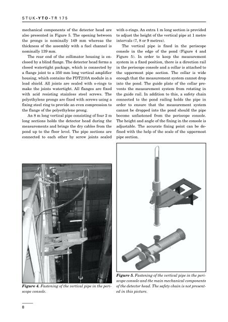
mechanical components of the detector head are<br />
also presented in Figure 5. The opening between<br />
the prongs is nominally 149 mm whereas the<br />
thickness of the assembly with a fuel channel is<br />
nominally 139 mm.<br />
The rear end of the collimator housing is enclosed<br />
by a blind flange. The detector head forms a<br />
closed watertight package, which is connected by<br />
a flange joint to a 350 mm long vertical amplifier<br />
housing, which contains the PDT210A module in a<br />
lead shield. All joints are sealed with o-rings to<br />
make the joints watertight. All flanges are fixed<br />
with acid resisting stainless steel screws. The<br />
polyethylene prongs are fixed with screws using a<br />
fixing steel ring to provide an even compression to<br />
the flange of the polyethylene prong.<br />
An 8 m long vertical pipe consisting of four 2 m<br />
long sections holds the detector head during the<br />
measurements and brings the dry cables from the<br />
pond up to the floor level. The pipe sections are<br />
connected to each other by screw joints sealed<br />
with o-rings. An extra 1 m long section is provided<br />
to adjust the height of the vertical pipe at 1 metre<br />
intervals (7, 8 or 9 metres).<br />
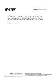
The vertical pipe is fixed in the periscope<br />
console in the edge of the pond (Figure 4 and<br />
Figure 5). In order to keep the measurement<br />
system in a fixed position, there is a direction rail<br />
in the periscope console and a collar is attached to<br />
the uppermost pipe section. The collar is wide<br />
enough that the measurement system cannot drop<br />
into the pond. The guide plate of the collar prevents<br />
the measurement system from rotating in<br />
the guide rail. In addition to this, a safety chain<br />
connected to the pond railing holds the pipe in<br />
order to ensure that the measurement system<br />
cannot be dropped into the pond should the pipe<br />
become unfastened from the periscope console.<br />
The height and angle of the fixing in the console is<br />
adjustable. The accurate fixing point can be defined<br />
with the help of the scale of the uppermost<br />
pipe section.<br />
Figure 4. Fastening of the vertical pipe in the periscope<br />
console.<br />
Figure 5. Fastening of the vertical pipe in the periscope<br />
console and the main mechanical components<br />
of the detector head. The safety chain is not presented<br />
in this picture.<br />
8