The Compleat Distiller
The Compleat Distiller
The Compleat Distiller

Create successful ePaper yourself
Turn your PDF publications into a flip-book with our unique Google optimized e-Paper software.
THE COMPLEAT DISTILLER 125<br />
APPENDIX 5<br />
CONSTANT LOAD HEATER CONTROLLER<br />
This appendix is written for those who already have practical experience in electronics, so we don't<br />
spend time explaining what all the components are and how they work. If you don't have such<br />
experience, then this appendix may perhaps stimulate interest in yet another useful and absorbing<br />
hobby. Only one small part of the circuit discussed here has any direct connection with power supply<br />
voltages, so if you get a friend who does have experience in electrical circuits to first check what you<br />
have done before connecting this part to the main power supply, then there is no reason at all why you<br />
shouldn't have a go at making the controller yourself.<br />
Operation<br />
This controller provides fully variable heater element control by means of burst fire control of two<br />
triacs, one feeding power to the heater element under control, and the other to a dummy load with the<br />
same wattage as the heater element. Another heater element of the same value as the boiler heater<br />
element is the obvious choice, heating a quantity of water in a separate container. As was noted in<br />
Chapter 4, the water in the separate container will heat up very slowly, as it's only absorbing heat<br />
energy not required for the distillation process. To save you looking that up again, it was worked out<br />
that it would take over 3 hours to heat 50 liters of water in such a "dummy load" from 20 o C to 60 o C.<br />
<strong>The</strong> reason for wanting to do it this way will be explained later.<br />
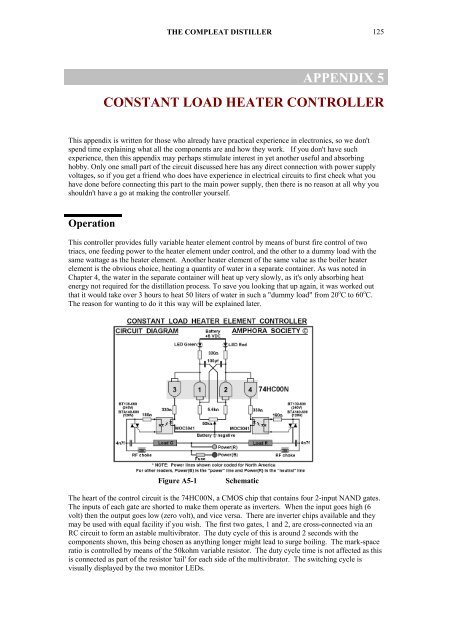
Figure A5-1<br />
Schematic<br />
<strong>The</strong> heart of the control circuit is the 74HC00N, a CMOS chip that contains four 2-input NAND gates.<br />
<strong>The</strong> inputs of each gate are shorted to make them operate as inverters. When the input goes high (6<br />
volt) then the output goes low (zero volt), and vice versa. <strong>The</strong>re are inverter chips available and they<br />
may be used with equal facility if you wish. <strong>The</strong> first two gates, 1 and 2, are cross-connected via an<br />
RC circuit to form an astable multivibrator. <strong>The</strong> duty cycle of this is around 2 seconds with the<br />
components shown, this being chosen as anything longer might lead to surge boiling. <strong>The</strong> mark-space<br />
ratio is controlled by means of the 50kohm variable resistor. <strong>The</strong> duty cycle time is not affected as this<br />
is connected as part of the resistor 'tail' for each side of the multivibrator. <strong>The</strong> switching cycle is<br />
visually displayed by the two monitor LEDs.