Icom M801E GMDSS Manual - Zanshin
Icom M801E GMDSS Manual - Zanshin
Icom M801E GMDSS Manual - Zanshin

You also want an ePaper? Increase the reach of your titles
YUMPU automatically turns print PDFs into web optimized ePapers that Google loves.
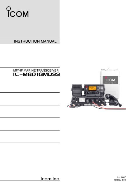
INSTRUCTION MANUAL<br />
MF/HF MARINE TRANSCEIVER<br />
iM801<strong>GMDSS</strong><br />
Jun. 2007<br />
for Rev. 1.00
FOREWORD<br />
Thank you for purchasing this <strong>Icom</strong> product. The IC-<br />
M801<strong>GMDSS</strong> MF/HF MARINE TRANSCEIVER is designed<br />
and built with <strong>Icom</strong>’s superior technology and craftsmanship.<br />
With proper care, this product should provide<br />
you with years of trouble-free operation.<br />
We want to take a couple of moments of your time to<br />
thank you for making the IC-M801<strong>GMDSS</strong> your radio of<br />
choice, and hope you agree with <strong>Icom</strong>’s philosophy of<br />
“technology first.” Many hours of research and development<br />
went into the design of your IC-M801<strong>GMDSS</strong>.<br />
D FEATURES<br />
❍Standard 4×8″ remote controller<br />
❍Built-in DSC meets ITU Class A requirement<br />
IMPORTANT<br />
READ THIS INSTRUCTION MANUAL<br />
CAREFULLY before attempting to operate the<br />
transceiver.<br />
SAVE THIS INSTRUCTION MANUAL. This<br />
manual contains important safety and operating instructions<br />
for the IC-M801<strong>GMDSS</strong>.<br />
EXPLICIT DEFINITIONS<br />
WORD<br />
RWARNING<br />
CAUTION<br />
NOTE<br />
DEFINITION<br />
Personal injury, fire hazard or electric<br />
shock may occur.<br />
Equipment damage may occur.<br />
If disregarded, inconvenience only. No<br />
risk or personal injury, fire or electric<br />
shock.<br />
PRECAUTIONS<br />
i<br />
R WARNING HIGH VOLTAGE! NEVER attach<br />
an antenna or internal antenna connector during<br />
transmission. This may result in an electrical shock or<br />
burn.<br />
RWARNING! NEVER connect the transceiver to<br />
an AC outlet directly. This may pose a fire hazard or<br />
result in an electric shock.<br />
R WARNING! NEVER mount the transceiver<br />
main unit overhead. The weight of the unit is approximately<br />
8.5 kg, but its apparent weight will increase<br />
several fold due to wave shocks or vibration. The unit<br />
must be mounted on a flat hard surface only.<br />
R NEVER connect a power source of more than<br />
31.2 V DC. This connection could cause a fire or ruin<br />
the transceiver.<br />
RNEVER place the transceiver where normal operation<br />
of the ship or vehicle may be hindered or where it<br />
could cause bodily injury.<br />
RNEVER let metal, wire or other objects touch any<br />
internal part or connectors on the rear panel of the<br />
transceiver. This may result in an electric shock.<br />
DO NOT use chemical agents such as benzine or alcohol<br />
when cleaning, as they can damage the transceiver<br />
surface.<br />
During maritime mobile operation, KEEP the transceiver<br />
and handset or microphone as far away as possible<br />
(at least 1 m) from the magnetic navigation compass<br />
to prevent erroneous indications.<br />
Use <strong>Icom</strong> handset or microphones only (supplied or optional).<br />
Other manufacturer’s handset or microphones<br />
have different pin assignments, and connection to the<br />
IC-M801<strong>GMDSS</strong> may damage the transceiver.<br />
AVOID using or placing the transceiver in areas with<br />
temperatures below –15°C or above +55°C.<br />
AVOID placing the transceiver in excessively dusty environments<br />
or in direct sunlight.<br />
AVOID placing the transceiver against walls or putting<br />
anything on top of the transceiver. This will obstruct<br />
heat dissipation.<br />
Place the unit in a secure place to avoid inadvertent<br />
use by children.<br />
BE CAREFUL! The transceiver main unit will become<br />
hot when operating the transceiver continuously for<br />
long periods.<br />
<strong>Icom</strong>, <strong>Icom</strong> Inc. and the are registered trademarks of<br />
<strong>Icom</strong> Incorporated (Japan) in the United States, the United<br />
Kingdom, Germany, France, Spain, Russia and/or other<br />
countries.<br />
IBM is a registered trademark of International Business Machines.
IN CASE OF EMERGENCY<br />
When your ship requires assistance, contact other ships and the Coast Guard by sending a distress call using digital<br />
selective calling on an emergency frequency.<br />
When immediate help is needed<br />
q Push and hold [DISTRESS] for 5 sec. until the<br />
short beeps become one long beep, to send the<br />
distress call.<br />
w After the appropriate traffic frequency is automatically<br />
selected (after an acknowledgement call is<br />
received), push and hold the PTT switch on the<br />
handset or microphone and send the following information.<br />
1. “MAY DAY, MAY DAY, MAY DAY.”<br />
2. “THIS IS……………” (name of ship)<br />
3. “LOCATED AT ……” (ship’s position)<br />
4. Give the reason for the distress call.<br />
5. Explain what assistance you need.<br />
6. Give additional information:<br />
• Ship type<br />
• Ship length<br />
• Ship color<br />
• Number of people on-board<br />
MAIN FIRMWARE REVISION NUMBER<br />
When potential problems exist<br />
q Push [DSC] to select DSC watch mode, if necessary.<br />
w Push [MODE SET] to select DSC menu, rotate [CH]<br />
to select “Geographical” then push [ENT].<br />
e Follow the guidance displayed on the LCD (bottom<br />
line), to set up the category, area, calling and traffic<br />
frequencies with [CH], [ENT] and keypad.<br />
r Push and hold [CALL] for 1 sec. until the short<br />
beeps become one long beep.<br />
t Transmit the appropriate information using voice.<br />
•DSC equipped ships may monitor your transmission.<br />
The main firmware revision number is displayed in the opening screen as below.<br />
The revision number is also displayed when MMSI code check screen is selected. (see page 43)<br />
Quick Reference<br />
1<br />
2<br />
3<br />
4<br />
5<br />
6<br />
7<br />
8<br />
9<br />
10<br />
<br />
123456789<br />
Main firmware revision<br />
number indication<br />
1.00<br />
11<br />
12<br />
13<br />
14<br />
15<br />
16<br />
17<br />
ii
TABLE OF CONTENTS<br />
FOREWORD...............................................................i<br />
IMPORTANT ............................................................. i<br />
EXPLICIT DEFINITIONS .......................................... i<br />
PRECAUTIONS ........................................................ i<br />
IN CASE OF EMERGENCY .....................................ii<br />
MAIN FIRMWARE REVISION NUMBER .................ii<br />
TABLE OF CONTENTS .......................................... iii<br />
1 OPERATING RULES AND GUIDELINES ........... 1<br />
2 PANEL DESCRIPTION ................................... 2–7<br />
■Controller (RC-25<strong>GMDSS</strong>) .............................. 2<br />
■Main unit ........................................................... 4<br />
■Handset (HS-98) .............................................. 5<br />
■LCD screen ...................................................... 6<br />
3 SELECTING A CHANNEL/FREQUENCY ...... 8–9<br />
■Selecting a channel .......................................... 8<br />
4 RECEIVE AND TRANSMIT ........................ 10–12<br />
■Basic voice transmit and receive .................. 10<br />
■Function for transmit ...................................... 10<br />
■Functions for receive ...................................... 11<br />
■FSK operation ................................................ 12<br />
5 CHANNEL NAME PROGRAMMING ................ 13<br />
6 FREQUENCY PROGRAMMING ................ 14–15<br />
■Frequency selection ....................................... 14<br />
■Programming a frequency .............................. 15<br />
7 DSC PREPARATION .................................. 16–17<br />
■MMSI code programming ............................... 16<br />
■Position and time programming ..................... 17<br />
8 CALL PROCEDURE ................................... 18–27<br />
■Distress call .................................................... 18<br />
■Individual call ................................................. 20<br />
■Group call ....................................................... 22<br />
■Geographical call ........................................... 24<br />
■Position request call ....................................... 26<br />
■Test call .......................................................... 27<br />
9 WHEN RECEIVING A CALL ...................... 28–39<br />
■To receive a DSC call ..................................... 28<br />
■Received information ..................................... 29<br />
■Deleting a memory ......................................... 30<br />
■Distress call .................................................... 31<br />
■Distress acknowledgement call ...................... 34<br />
■Distress relay call ........................................... 35<br />
■Individual call ................................................. 36<br />
■Group call ....................................................... 38<br />
■Polling call ...................................................... 38<br />
■Position request call ....................................... 39<br />
■Geographical area call ................................... 39<br />
10 MEMORY OPERATION .................................... 40<br />
■Memory description ........................................ 40<br />
■Memory writing ............................................... 40<br />
■Memory reading/transmitting/deleting ............ 40<br />
11 DSC MENU OPERATION ........................... 41–44<br />
■General .......................................................... 41<br />
■ID input ........................................................... 41<br />
■Frequency input ............................................. 42<br />
■Verifying self-ID .............................................. 43<br />
■Self testing ..................................................... 43<br />
■Scanning distress frequency setting .............. 43<br />
■Memory reading/deleting ............................... 44<br />
■Printing out the DSC memory contents .......... 44<br />
12 SET MODE ................................................. 45–49<br />
■Quick set mode .............................................. 45<br />
■Initial set mode ............................................... 46<br />
13 CONNECTION AND INSTALLATION ........ 50–63<br />
■Supplied accessories ..................................... 50<br />
■Basic connections ...........................................51<br />
■Advanced connections ................................... 52<br />
■Ground connection ......................................... 53<br />
■Power source ................................................. 54<br />
■Antenna .......................................................... 55<br />
■Mounting ........................................................ 56<br />
■Using the optional MB-108 ............................. 58<br />
■Using the optional MB-75 ............................... 59<br />
■Transceiver dimensions ................................. 60<br />
■Fuse replacement .......................................... 61<br />
■Connector information .................................... 62<br />
14 SPECIFICATIONS ............................................ 64<br />
15 OPTIONS .......................................................... 65<br />
16 TEMPLATE ................................................. 67–70<br />
■Remote controller (RC-25<strong>GMDSS</strong>) ................ 67<br />
■Speaker (SP-24E) .......................................... 69<br />
17 ANTENNA AND GROUNDING<br />
CONSIDERATIONS ................................... 71–73<br />
iii
OPERATING RULES AND GUIDELINES<br />
1<br />
Before transmitting, monitor the channel you wish to<br />
use so as to avoid interrupting transmissions already<br />
in progress.<br />
• CALL PROCEDURE<br />
Calls must be properly identified and the time limit<br />
must be respected.<br />
q Give your call sign each time you call another ship<br />
or coast guard station. If you have no call sign,<br />
identify the station by giving your ship name and the<br />
name of the licensee.<br />
w Give your call sign at the end of each transmission<br />
that lasts more than 3 min.<br />
e You must break and give your call sign at least once<br />
every 15 min. during long ship-to-shore calls.<br />
r Keep your unanswered calls short, less than<br />
30 sec. Do not repeat a call for 2 min.<br />
t Unnecessary transmissions are not allowed.<br />
• PRIORITIES<br />
q Read all rules and regulations pertaining to priorities<br />
and keep an up-to-date copy handy. Safety and<br />
distress calls take priority over all others.<br />
w False or fraudulent distress signals are prohibited<br />
and punishable by law.<br />
•PRIVACY<br />
q Information overheard but not intended for you, cannot<br />
lawfully be used in any way.<br />
w Indecent or profane language is prohibited.<br />
• LOGS<br />
q All distress, emergency and safety calls must be<br />
recorded in complete details. Log data activity is<br />
usually recorded in 24 hour time. Universal Time<br />
Coordinated (UTC) is frequently used.<br />
w Adjustments, repairs, channel frequency changes<br />
and authorized modifications affecting electrical operation<br />
of the equipment must be kept in the maintenance<br />
log; entries must be signed by the authorized<br />
licensed technician performing or supervising<br />
the work.<br />
• RADIO LICENSES<br />
(1) SHIP STATION LICENSE<br />
You must have a current radio station license before<br />
using the transceiver. It is unlawful to operate a ship<br />
station which is not licensed.<br />
Inquire through your dealer or the appropriate government<br />
agency for a Ship-Radiotelephone license application.<br />
This government-issued license states the call<br />
sign which is your craft’s identification for radio purposes.<br />
(2) OPERATOR’S LICENSE<br />
A Restricted Radiotelephone Operator Permit is the license<br />
most often held by small ship radio operators<br />
when a radio is not required for safety purposes.<br />
The Restricted Radiotelephone Operator Permit must<br />
be posted or kept with the operator. Only a licensed<br />
radio operator may operate the transceiver.<br />
However, non-licensed individuals may talk over a<br />
transceiver if a licensed operator starts, supervises,<br />
and ends the call and makes the necessary log entries.<br />
Keep a copy of the current government rules and regulation<br />
handy.<br />
Quick Reference<br />
1<br />
1
2<br />
PANEL DESCRIPTION<br />
■ Controller (RC-25<strong>GMDSS</strong>)<br />
Function display (pgs. 6, 7)<br />
!7<br />
!6<br />
!5<br />
!4<br />
q<br />
DISTRESS<br />
w<br />
!3<br />
e<br />
r<br />
!2<br />
t<br />
y u i o !0 !1<br />
q DISTRESS SWITCH [DISTRESS] (p. 18)<br />
Push and hold for 5 sec. (approx.) to make a distress<br />
call.<br />
w CALL SWITCH [CALL]<br />
Push and hold for 1 sec. to start calling after DSC<br />
contents are setup.<br />
e CANCEL SWITCH [CANCEL]<br />
Cancels a distress or DSC repeat call.<br />
r HEADPHONE JACK [ ]<br />
Accepts headphones.<br />
•Output power: 2.5 mW with a 16 Ω load<br />
(stereo/monaural)<br />
t MICROPHONE CONNECTOR [MIC]<br />
Accepts the supplied or optional microphone.<br />
• See p. 65 for appropriate microphones.<br />
• See p. 62 for microphone connector information.<br />
y GROUP SELECTOR [GRP]<br />
➥Selects groups in 20 channel steps and ITU marine<br />
channel groups. (p. 8)<br />
➥Selects items during quick/initial set mode, etc.<br />
u CHANNEL SELECTOR [CH]<br />
➥Selects an operating channel within the selected<br />
channel group such as ITU channels. (p. 8)<br />
•User channels can be selected from 1 to 160 (max.)<br />
in sequence regardless of the channel group.<br />
➥Changes setting or value of the selected item<br />
during quick/initial set mode, etc.<br />
i RX/CLARITY SWITCH [RX CLAR]<br />
➥After pushing [F], turns the clarity function ON<br />
and OFF. (p. 12)<br />
•[CH] is used for clarity control.<br />
➥During DSC watch mode, enters Received Call<br />
Log screen. (p. 29)<br />
•[CH] is used for distress and other call selection.<br />
o POWER SWITCH [POWER]<br />
➥Push to turn the power ON.<br />
➥Push and hold for 1 sec. to turn the power OFF.<br />
!0 TX/TRANSMIT FREQUENCY SWITCH [TX TXF]<br />
➥After pushing [F], displays the transmit frequency,<br />
and opens the squelch. Checks and monitors<br />
the transmit frequency while holding. (p. 10)<br />
➥During DSC watch mode, enters TX memory select<br />
screen. (p. 40)<br />
•[CH] is used for memory selection.<br />
!1 VOLUME CONTROL [VOL]<br />
Adjusts the audio output level.<br />
•Audio does not come from the speaker when:<br />
- The speaker OFF switch is turned ON.<br />
- The squelch function is turned ON and no signal is<br />
being received.<br />
-Pick the handset up with speaker switch “ ” position.<br />
(p. 5)<br />
- During DSC watch mode.<br />
2
PANEL DESCRIPTION<br />
2<br />
!2 FREQUENCY/CHANNEL SWITCH [FREQ/CH]<br />
➥Selects indication type: (p. 8)<br />
When channel comment indication is ON;<br />
switches channel comment indication ON and<br />
OFF.<br />
When channel comment indication is OFF;<br />
switches transmit frequency indication ON and<br />
OFF.<br />
➥After pushing [F], enters channel name programming<br />
mode, when channel comment indication<br />
is ON. (p. 13)<br />
!3 KEYPAD<br />
➥Inputs numeral “1” for channel number<br />
input, etc.<br />
➥Inputs “1,” “Q,” “Z,” “q,” “z” or space for<br />
channel comment input.<br />
➥After pushing [F], turns the noise<br />
blanker function ON and OFF. (p. 11)<br />
➥Inputs numeral “2” for channel number<br />
input, etc.<br />
➥Inputs “2,” “A,” “B,” “C,” “a,” “b” or “c” for<br />
channel comment input.<br />
➥After pushing [F], turns the squelch<br />
function ON and OFF. (p. 11)<br />
➥Inputs numeral “3” for channel number<br />
input, etc.<br />
➥Inputs “3,” “D,” “E,” “F,” “d,” “e” or “f” for<br />
channel comment input.<br />
➥After pushing [F], starts and stops the<br />
scan function. (p. 9)<br />
➥Inputs numeral “4” for channel number<br />
input, etc.<br />
➥Inputs “4,” “G,” “H,” “I,” “g,” “h” or “i” for<br />
channel comment input.<br />
➥After pushing [F], turns the external<br />
speaker output ON and OFF. (p. 10)<br />
➥Inputs numeral “5” for channel number<br />
input, etc.<br />
➥Inputs “5,” “J,” “K,” “L,” “j,” “k” or “l” for<br />
channel comment input.<br />
➥After pushing [F], turns the AGC OFF<br />
function ON and OFF. (p. 11)<br />
➥Inputs numeral “6” for channel number<br />
input, etc.<br />
➥Inputs “6,” “M,” “N,” “O,” “m,” “n” or “o” for<br />
channel comment input.<br />
➥After pushing [F], enters the RF gain adjustment<br />
mode. (p. 11)<br />
➥Inputs numeral “7” for channel number<br />
input, etc.<br />
➥Inputs “7,” “P,” “R,” “S,” “p,” “r” or “s” for<br />
channel comment input.<br />
➥Inputs numeral “8” for channel number<br />
input, etc.<br />
➥Inputs “8,” “T,” “U,” “V,” “t,” “u” or “v” for<br />
channel comment input.<br />
➥After pushing [F], push for 1 sec. to print<br />
out the DSC contents, etc. (p. 44)<br />
➥Inputs numeral “9” for channel number<br />
input, etc.<br />
➥Inputs “9,” “W,” “X,” “Y,” “w,” “x” or “y” for<br />
channel comment input.<br />
➥Inputs numeral “0” for channel number<br />
input, etc.<br />
➥Inputs “0” and symbols (. , ()*+-<br />
/@) for channel comment input.<br />
➥After pushing [F], selects LCD backlight<br />
brightness.<br />
➥Fixes input of channel number and channel<br />
comment, etc.<br />
➥When pushed for 1 sec., stores programmed<br />
frequency, operating mode and<br />
memory comment into a channel.<br />
➥Clears entered digits and retrieves the<br />
previous frequency, channel or channel<br />
names during setting.<br />
!4 FUNCTION SWITCH [F]<br />
After pushing, activates the secondary functions.<br />
•“ ” appears when a secondary function can be accessed.<br />
!5 TUNE/THROUGH SWITCH [TUNE THRU]<br />
➥Starts tuning the connected AT-141 HF AUTOMATIC<br />
ANTENNA TUNER.<br />
•“TUNE” appears when tuned.<br />
•When the tuner cannot tune the antenna, the tuning<br />
circuit is bypassed automatically after 15 sec.<br />
➥After pushing [F], bypasses the connected antenna<br />
tuner. (p. 12)<br />
•“THRU” appears instead of “TUNE” indication.<br />
!6 MODE/SET SWITCH [MODE SET]<br />
➥Push to select an operating mode.<br />
•J3E (USB), H3E (AM), LSB, J2B (AFSK), F1B (FSK),<br />
and A1A (CW) modes are available, depending on<br />
version or countries.<br />
➥After pushing [F], enters quick set mode. (p. 45)<br />
➥During DSC watch mode, enters DSC menu.<br />
!7 DSC SWITCH [DSC]<br />
Switches DSC watch mode and voice communication<br />
mode when pushed.<br />
2<br />
3
2 PANEL DESCRIPTION<br />
■ Main unit<br />
q w e<br />
!1<br />
!0<br />
!2<br />
o<br />
i<br />
u<br />
y<br />
t<br />
r<br />
q GROUND TERMINAL<br />
IMPORTANT! Connects a ship’s ground. See<br />
page 53 for details.<br />
w DC POWER TERMINALS (pgs. 51, 54)<br />
Accepts 24 V DC through the supplied DC power<br />
cables.<br />
Red terminal is for positive and black terminal is for<br />
negative connection.<br />
e DC ISOLATE SWITCH [DC ISOLATE] (p. 51)<br />
Turns the transceiver’s main power ON and OFF.<br />
r TUNER CONTROL SOCKET (pgs. 51, 55)<br />
Connects a control cable to the antenna tuner, AT-<br />
141.<br />
A female connector kit is supplied for antenna tuner<br />
connection.<br />
t ANTENNA CONNECTOR 1 (pgs. 51, 55)<br />
Connects a 50 Ω HF band antenna via a 50 Ω<br />
matched coaxial cable with a PL-259 plug for both<br />
transmit and receive operation.<br />
y PRINTER CONNECTOR (pgs. 52, 63)<br />
Connects an IBM ® centronics or compatible printer<br />
to print out received DSC information automatically<br />
or manually.<br />
u REMOTE CONNECTOR [REMOTE] (p. 63)<br />
Connects a cable (D-sub 9-pin) for remote control<br />
in the IEC61162-1 format.<br />
i MODEM CONNECTOR [AF/MOD] (pgs. 52, 62)<br />
Connects to an NBDP (Narrow Band Direct Printing)<br />
or FAX system via a D-sub 15-pin cable.<br />
This connector can also be used as SSB telephony<br />
interface (600 Ω).<br />
o CONTROLLER CONNECTOR [CONTROLLER]<br />
(p. 51)<br />
Connects the supplied remote controller, RC-<br />
25<strong>GMDSS</strong>.<br />
!0 GPS CONNECTOR [GPS] (p. 52)<br />
Input position and UTC data (IEC6112-1 format),<br />
such as from a GPS receiver, etc., for setting your<br />
positioning and time data automatically without<br />
manual input for DSC operation.<br />
GPS IN (+)<br />
RCA<br />
GPS IN (–)<br />
!1 SPEAKER JACK [SP] (p. 51)<br />
Connects the supplied external speaker, SP-24E.<br />
!2 ANTENNA CONNECTOR 2 (p. 51)<br />
Connects a 50 Ω HF band antenna via a 50 Ω<br />
matched coaxial cable with a PL-259 plug for DSC<br />
receiver.<br />
IMPORTANT!: An HF antenna should be connected<br />
to this antenna connector,<br />
otherwise no DSC call can be received.<br />
✔For detailed “ANTENNA AND GROUNDING CON-<br />
SIDERATIONS,” see pages 71 to 73.<br />
4
PANEL DESCRIPTION<br />
2<br />
■ Handset (HS-98)<br />
q<br />
Cradle<br />
Handset<br />
w<br />
e<br />
2<br />
q SPEAKER SWITCH<br />
Toggle the connected external speaker output ON<br />
and OFF when pick the handset up.<br />
• When the switch is set to “ ” position<br />
- Emits the receiving audio from the connected external<br />
speaker.<br />
• When the switch is set to “ ” position<br />
- Mutes the connected external speaker output.<br />
•The receiving audio can be heard from the earpiece<br />
of the handset.<br />
- Replace the handset into the cradle to emits the<br />
receiving audio from the connected external<br />
speaker.<br />
w HANDSET CONNECTOR<br />
Connects to [MIC] connector on the remote controller.<br />
(p. 51)<br />
e PTT SWITCH [PTT]<br />
Push and hold to transmit; release to receive.<br />
5
2 PANEL DESCRIPTION<br />
■ LCD screen<br />
The IC-M801<strong>GMDSS</strong> has 2 indication types, one is<br />
channel name indication and the other is frequency indication.<br />
These indication types can be switched with a<br />
push of a button, depending on set mode’s setting.<br />
See pages 8 and 47 for display type settings.<br />
• Channel name indication<br />
w e r t<br />
q<br />
!5<br />
!4<br />
!3<br />
!2<br />
RX TUNE J3E SIMP<br />
CLAR<br />
0<br />
SP<br />
TX<br />
AGC<br />
CH ---GPS---<br />
NB SQL<br />
Lat 45 59'N<br />
0 1 2 3 4A<br />
Lon134 44'E<br />
16:23<br />
y<br />
u<br />
i<br />
o<br />
!1<br />
!0<br />
• Frequency indication<br />
w e r t<br />
q<br />
RX TUNE J3E SIMP<br />
!5<br />
!4<br />
!3<br />
!2<br />
TX<br />
NB SQL<br />
CH<br />
SP<br />
AGC<br />
CLAR 0<br />
UTC 16:23<br />
u<br />
i<br />
y<br />
!1<br />
o<br />
!0<br />
!6<br />
• DSC watch mode indication<br />
@2<br />
!5<br />
q<br />
!9<br />
!8<br />
u<br />
!7<br />
2 4 6 8 12 16<br />
ACK<br />
RX<br />
MMSI 123456789<br />
12.345.5 F1B<br />
GPS 34 34.000N<br />
SP<br />
134 34.000E<br />
12:34<br />
Exit Unread MSG<br />
t<br />
@0<br />
e<br />
o<br />
@1<br />
6
PANEL DESCRIPTION<br />
2<br />
q RECEIVE INDICATOR<br />
“RX” appears when signals are received or the<br />
squelch is open.<br />
w TUNE INDICATOR<br />
“TUNE” blinks while tuning. (p. 10)<br />
•“TUNE” appears after tuning is completed with AT-141.<br />
•“THRU” appears when the tuner through function is activated.<br />
•“SWR” appears when the antenna SWR worsens during<br />
transmit, depending on the transmit output power. If it<br />
appears, check your antenna system.<br />
e OPERATING MODE INDICATOR<br />
Shows the selected operating mode.<br />
•“J3E,” “USB,” “H3E,” “AM,” “LSB,” “J2B,” “AFS,”<br />
“F1B,” “FSK,” “A1A” or “CW” appears depending on<br />
operating mode and setting.<br />
r SIMPLEX/DUPLEX INDICATOR<br />
“SIMP” appears when a simplex channel is selected.<br />
“DUP” appears when a duplex channel is selected.<br />
t FUNCTION INDICATOR<br />
“ ” appears when a secondary function can be accessed.<br />
y CLARITY INDICATOR (p. 12)<br />
“CLAR” appears when the clarity function is activated<br />
and shows shifting frequency in “Hz.”<br />
u SPEAKER OFF INDICATOR (p. 10)<br />
“ SP”<br />
appears when the speaker output is turned<br />
OFF.<br />
i AGC OFF INDICATOR (p. 11)<br />
“ AGC” appears when the AGC OFF function is<br />
turned ON.<br />
o POSITION/UTC TIME INDICATOR (p. 17)<br />
Shows position and/or UTC (or local) time. When<br />
an IEC61162-1 data is applied to [GPS], the indication<br />
is up dated automatically.<br />
•When no IEC61162-1 data is applied, the position and<br />
UTC time must be set in advance.<br />
•“GPS” appears when an IEC61162-1 data is applied to<br />
[GPS], “MNL” appears when the position is manually<br />
set.<br />
•“UTC” appears when the offset time has not been programmed.<br />
(No “UTC” indication when offset time is programmed<br />
and shows local time.)<br />
!0 CHANNEL NUMBER INDICATION<br />
Shows the selected channel number.<br />
!1 S/ANTENNA CURRENT INDICATOR<br />
Shows relative driving antenna current levels during<br />
transmit and receiving signal strength during receive.<br />
!2 NOISE BLANKER INDICATOR (p. 11)<br />
“NB” appears when the noise blanker function is activated.<br />
!3 SQUELCH INDICATOR (p. 11)<br />
“SQL” appears when the squelch is ON.<br />
!4 TRANSMIT INDICATOR<br />
➥“TX” appears during transmit.<br />
➥“TX” blinks while monitoring a transmit frequency.<br />
(p. 10)<br />
!5 CHANNEL NAME/RECEIVE FREQUENCY<br />
READOUT<br />
➥Shows the programmed channel names.<br />
➥Shows receive frequency when no channel name<br />
is programmed, or during frequency indication.<br />
➥During DSC watch mode, displays “DSC WATCH.”<br />
!6 TRANSMIT FREQUENCY READOUT<br />
Shows transmit frequency.<br />
!7 OPERATING GUIDE INDICATION<br />
During DSC watch mode operation, shows several<br />
types of guidance, according to the selected condition.<br />
!8 SCANNING FREQUENCY READOUT<br />
During DSC watch mode operation, shows the programmed<br />
scan frequency.<br />
•Decimal points blink.<br />
!9 MMSI CODE INDICATION<br />
During DSC watch mode operation, shows the programmed<br />
MMSI code.<br />
@0 AUTO ACKNOWLEDGEMENT INDICATOR<br />
Appears when the automatic acknowledgement<br />
function is set to ON. (p. 48)<br />
@1 UNREAD MESSAGE INDICATOR<br />
Appears when an unread DSC message is available.<br />
@2 SCANNING DISTRESS FREQUENCY INDICATOR<br />
Shows the scanning distress frequency initials for<br />
DSC operation. (p. 43)<br />
2<br />
7
3<br />
SELECTING A CHANNEL/FREQUENCY<br />
■ Selecting a channel<br />
The transceiver has 160 user channels and ITU channels.<br />
However, the number of user channels can be<br />
optionally restricted.<br />
DDisplay selection<br />
FREQUENCY indication<br />
RX J3E SIMP<br />
CHANNEL indication<br />
RX J3E SIMP<br />
CH<br />
16:23<br />
0 1 2 3 4A<br />
CH ---GPS---<br />
Lat 45 59'N<br />
Lon134 44'E<br />
16:23<br />
NOTE: Channel name (alphanumeric) may not appear<br />
during frequency indication depending on initial<br />
set mode setting. (p. 47)<br />
DUsing the channel selector<br />
The transceiver has two large controls for group selection<br />
and channel selection. The [GRP] changes<br />
channels in 20 channel increments and selects ITU<br />
channel groups; and the [CH] selects each channel.<br />
[EXAMPLE]: Selection with the [GRP]<br />
RX J3E SIMP<br />
CH ---GPS---<br />
Lat 45 59'N<br />
Lon134 44'E<br />
0 1 2 3 4A 16:23<br />
RX J3E SIMP<br />
RX J3E DUP<br />
CH ---GPS---<br />
Lat 45 59'N<br />
Lon134 44'E<br />
0 1 2 3 4A 16:23<br />
RX J3E SIMP<br />
CH ---GPS---<br />
Lat 45 59'N<br />
Lon134 44'E<br />
0 1 2 3 4A 16:23<br />
CH ---GPS---<br />
Lat 45 59'N<br />
Lon134 44'E<br />
0 1 2 3 4A 16:23<br />
[GRP]<br />
[CH]<br />
q Rotate [GRP] to select the desired channel group<br />
as shown at right and/or below.<br />
w Rotate [CH] to select the desired channel.<br />
RX J3E SIMP<br />
CH ---GPS---<br />
Lat 45 59'N<br />
Lon134 44'E<br />
0 1 2 3 4A 16:23<br />
RX J3E SIMP<br />
CH ---GPS---<br />
Lat 45 59'N<br />
Lon134 44'E<br />
0 1 2 3 4A 16:23<br />
RX J3E DUP<br />
CH ---GPS---<br />
Lat 45 59'N<br />
Lon134 44'E<br />
0 1 2 3 4A 16:23<br />
ITU SSB channels<br />
RX J3E SIMP<br />
RXå<br />
J3E SIMP<br />
CH ---GPS---<br />
Lat 45 59'N<br />
Lon134 44'E<br />
0 1 2 3 4A 16:23<br />
CH ---GPS---<br />
Lat 45 59'N<br />
Lon134 44'E<br />
0 1 2 3 4A 16:23<br />
8<br />
CHANNEL GROUPS<br />
* 1 [GRP] changes in 20 channels steps. * 2 SITOR use— no group separation.<br />
Channel No. Description Channel No. Description Channel No. Description<br />
1 to 160 User Ch.* 1 1201 to 1241 12 MHz ITU duplex Ch. 22-1 to 22-9 22 MHz ITU simplex Ch.<br />
401 to 427 4 MHz ITU duplex Ch. 12-1 to 12-9 12 MHz ITU simplex Ch. 2501 to 2510 25 MHz ITU duplex Ch.<br />
4-1 to 4-9 4 MHz ITU simplex Ch. 1601 to 1656 16 MHz ITU duplex Ch. 25-1 to 25-9 25 MHz ITU simplex Ch.<br />
601 to 608 6 MHz ITU duplex Ch. 16-1 to 16-9 16 MHz ITU simplex Ch. C1-1 to C1-21 C1 channels<br />
6-1 to 6-9 6 MHz ITU simplex Ch. 1801 to 1815 18 MHz ITU duplex Ch. C2-1 to C2-31 C2 channels<br />
801 to 832 8 MHz ITU duplex Ch. 18-1 to 18-9 18 MHz ITU simplex Ch. 4001 to 25040 ITU FSK duplex Ch.* 2<br />
8-1 to 8-9 8 MHz ITU simplex Ch. 2201 to 2253 22 MHz ITU duplex Ch.
SELECTING A CHANNEL/FREQUENCY<br />
3<br />
DUsing the keypad<br />
Direct channel selection via the keypad is available<br />
for quick channel selection.<br />
q Enter the desired channel number via the keypad.<br />
•Pushing [CE] clears input digits and retrieves the channel.<br />
•A user channel is selected when channel 1–160 is<br />
input (max. number may be optionally restricted).<br />
•An ITU SSB channel is selected when channel numbers<br />
higher than 401 are input.<br />
•When selecting an ITU simplex channel, push [0 DIM]<br />
three times to input “– (dash).”<br />
(e.g. When selecting the channel 4-1;<br />
— push [4 SP × ], [0 DIM], [0 DIM], [0 DIM] then [1 NB].)<br />
w Push [ENT] to select the channel.<br />
[EXAMPLE]: Selecting channel 158<br />
RX<br />
RX<br />
RX<br />
L<br />
L<br />
J3E<br />
J3E<br />
H<br />
J3E<br />
H<br />
CH ---GPS---<br />
Lat 45 59'N<br />
Lon134 44'E<br />
16:23<br />
CH ---GPS---<br />
Lat 45 59'N<br />
Lon134 44'E<br />
16:23<br />
RX J3E<br />
CH ---GPS---<br />
Lat 45 59'N<br />
Lon134<br />
SIMP<br />
44'E<br />
L<br />
H 16:23<br />
DUsing scan function<br />
The transceiver has automatic channel or frequency<br />
change capability (scan function). There are 3 types<br />
of scan functions available to suit your needs.<br />
Channel scan/Channel resume scan<br />
Ch 1<br />
Ch 2 Ch 3<br />
Ch 20<br />
Programmed scan<br />
Ch 4<br />
Ch 159 Ch 160<br />
When resume OFF;<br />
scan does not pause even<br />
if a signal is received.<br />
When resume ON;<br />
scan pauses for 10 sec.,<br />
then resumes, or resumes<br />
after 2 sec. from when the<br />
signal disappears.<br />
Scans the frequency range<br />
between the programmed<br />
frequencies on channels<br />
159 and 160.<br />
Scans fast when squelch is<br />
closed and slowly when<br />
squelch is open.<br />
CH ---GPS---<br />
Lat 45 59'N<br />
Channel scan and channel resume scan increase<br />
channels within a 20 channel range, such as Ch 1 to<br />
Ch 20, Ch 141 to Ch 160, etc., in user channels; or<br />
all channels in the group of ITU channels.<br />
Programmed scan scans frequencies within the frequency<br />
range between user channels 159 and 160.<br />
Scan type selection is available in initial set mode.<br />
See p. 46 for the selection.<br />
SCAN OPERATION<br />
q Rotate [GRP] and [CH], or use the keypad to select<br />
your desired channel group.<br />
•This operation is not necessary for programmed scan.<br />
w Push [F] then [2 SQL] to turn OFF the squelch<br />
function, if programmed scan is selected.<br />
e Push [F] then [3 SCAN] to start the scan.<br />
r To stop the scan, repeat step e again.<br />
•[CH] rotation or pushing some other switches also<br />
stops the scan.<br />
3<br />
9
4<br />
RECEIVE AND TRANSMIT<br />
■ Basic voice transmit and receive<br />
q Check the following in advance.<br />
➥Handset or microphone is connected.<br />
➥No “SQL” indication.<br />
•If “SQL” appears, push [F] then [2 SQL] to turn the<br />
squelch OFF.<br />
➥No “ SP” indication.<br />
•If “ SP” appears, push [F] then [4 SP × ] to activate<br />
the speaker.<br />
➥The clarity function is not activated.<br />
•If the clarity function is activated, push [F] then<br />
[RX CLAR] to turn the function OFF.<br />
Microphone<br />
connector<br />
[4 SP × ] [2 SQL]<br />
[F]<br />
[RX CLAR]<br />
w Rotate [GRP] and [CH] to select the desired channel<br />
to be received.<br />
•When receiving a signal, the S-meter shows the signal<br />
strength.<br />
e Adjust [VOL] to the desired audio level when receiving<br />
a signal.<br />
r Push [MODE SET] to select the desired operating<br />
mode.<br />
t Push [TUNE THRU] to tune the antenna tuner, if connected.<br />
•Skip this operation when the “AUTO TUNE” is set to ON<br />
in initial set mode (p. 46).<br />
y To transmit on the channel, push and hold the PTT<br />
switch on the handset or microphone.<br />
•“TUNE” blinks for 1 to 2 sec. for the first transmission<br />
on a channel when the automatic tuning function is activated.<br />
u Speak into the handset or microphone at your normal<br />
voice level.<br />
•The RF meter shows the output power according to your<br />
voice level.<br />
•If “SWR” appears, check your antenna system.<br />
i Release the PTT switch to return to receive.<br />
■ Function for transmit<br />
DTransmit frequency check<br />
When “DUP” appears in the display such as for a<br />
ship-to-ship channel, the transmit frequency differs<br />
from the receive frequency.<br />
In such cases, the transmit frequency should be monitored<br />
before transmitting to prevent interference to<br />
other stations.<br />
➥Push [F] then push and hold [TX TXF] to monitor<br />
the transmit frequency.<br />
[F][TX TXF]<br />
•“TX” blinks and the display shows the transmit frequency.<br />
10
RECEIVE AND TRANSMIT<br />
4<br />
■ Functions for receive<br />
DSquelch function<br />
The squelch function detects signals with voice components<br />
and squelches (mutes) unwanted signals<br />
such as unmodulated beat signals. This provides<br />
quiet stand-by.<br />
When you need to receive weak signals, the squelch<br />
should be turned OFF.<br />
➥Push [F] then [2 SQL] to switch the function ON<br />
and OFF.<br />
•See page 45 for the squelch level adjustment.<br />
[F]<br />
[2 SQL]<br />
•“SQL” appears when the squelch function is turned ON.<br />
DNoise blanker<br />
The noise blanker function reduces pulse type noise<br />
such as that coming from engine ignitions, etc.<br />
The noise blanker may distort reception of strong signals.<br />
In such cases, the noise blanker should be<br />
turned OFF.<br />
➥Push [F] then [1 NB] to switch the function ON and<br />
OFF.<br />
•See page 45 for the noise blanker level adjustment.<br />
[F] [1 NB]<br />
•“NB” appears when the NB function is turned ON.<br />
4<br />
DAGC OFF function<br />
The receive gain is automatically adjusted according<br />
to received signal strength with the AGC (Automatic<br />
Gain Control) function to prevent distortion from<br />
strong signals and to obtain a constant output level.<br />
When receiving weak signals with adjacent strong<br />
signals or noise, the AGC function may reduce the<br />
sensitivity. In this situation, the AGC function should<br />
be deactivated.<br />
➥Push [F] then [5 AGC × ] to switch the function ON<br />
and OFF.<br />
•“<br />
[F] [5 AGC × ]<br />
AGC” appears when the AGC function is turned OFF.<br />
DRF gain setting<br />
The receiver gain can be reduced with the RF gain<br />
setting. This may help to remove undesired weak signals<br />
while monitoring strong signals.<br />
q Push [F] then [6 RF-G] to select the RF gain set<br />
mode, as shown below.<br />
Usually, the AGC function reduces the RF gain according<br />
to the receive signal strength and these weak<br />
signals are removed. However, during no signal reception,<br />
these weak signals may not be heard.<br />
In such cases, the RF gain may be useful for setting a<br />
minimum level at which to hear signals.<br />
w Rotate [CH] to set the desired minimum cutting<br />
level.<br />
•“0 (low sensitivity)” to “9 (max. sensitivity)” are available.<br />
•S-meter shows the minimum permitted level.<br />
e Push any key to exit the RF gain set mode.<br />
11
4 RECEIVE AND TRANSMIT<br />
■ Functions for receive (continued)<br />
DClarity control<br />
Voice signals received from other stations may be difficult<br />
to receive. This may sometimes happen if a station<br />
is transmitting slightly off frequency. In such cases,<br />
you can compensate by using the clarity control.<br />
q Push [F] then [RX CLAR] to switch the function ON<br />
and OFF.<br />
•“CLAR” and shifting value with direction appear.<br />
w Rotate [CH] to improve the audio readability.<br />
•Adjustable between ±150 Hz in 10 Hz steps.<br />
[CH]<br />
[F]<br />
[RX CLAR]<br />
DTuner through function<br />
In the combination with IC-M801<strong>GMDSS</strong> and optional<br />
AT-141, the tuner through function can be used.<br />
By bypassing the tuner unit, the receiver gain in particular<br />
frequency band may be improved depending<br />
on your antenna element length.<br />
➥While “TUNE” is displayed, push [F] then<br />
[TUNE THRU] to tuner through function ON.<br />
•“THRU” appears instead of “TUNE” indicator.<br />
•Push [TUNE THRU] to turn the function OFF.<br />
[TUNE THRU] [F]<br />
■ FSK operation<br />
The transceiver has AFSK operation capability when<br />
an AFSK terminal unit is connected— use J2B for<br />
AFSK operation.<br />
q Connect an AFSK terminal unit to the [AF/MOD]<br />
socket as shown at right.<br />
w Select the desired channel to operate AFSK mode.<br />
e Push [MODE SET] several times to select J2B.<br />
r Operate the AFSK terminal unit.<br />
NOTE:<br />
Some transceivers may operate 1.7 kHz higher<br />
than the IC-M801<strong>GMDSS</strong>’s J2B mode even when<br />
the same displayed frequencies are in use.<br />
AFSK terminal unit connection<br />
5<br />
15<br />
11<br />
To pin 5<br />
To pins 3, 4<br />
1<br />
To pins 1, 2<br />
To pin 9<br />
Tx/Rx control<br />
AF ground<br />
AF input<br />
MOD ground<br />
MOD output<br />
Ground<br />
AFSK terminal unit<br />
12
CHANNEL NAME PROGRAMMING<br />
5<br />
Up to 8-character channel names can be assigned for<br />
each user and ITU channel. This may be helpful for indicating<br />
the frequency usage, ship name, etc.<br />
NOTE: The display type must be set to “CH-<br />
NAME” to display/program the channel names in initial<br />
set mode. (p. 47).<br />
D Programming<br />
q Select the desired channel to be programmed.<br />
w Push [FREQ/CH] to select channel indication<br />
mode, if desired.<br />
e Push [F] then [FREQ/CH].<br />
•The 1st character for the channel names blinks.<br />
RX J3E DUP<br />
0 1 2 3 4A<br />
CH ---GPS---<br />
Lat 45 59'N<br />
Lon134 44'E<br />
16:23<br />
r Rotate [CH] selector to select the character for<br />
channel names.<br />
•See the table below for available characters.<br />
t Push the keypad several times to enter that character.<br />
RX J3E DUP<br />
0 1 2 3 4A<br />
y Repeat steps r and t to enter the channel name.<br />
u Push [ENT] for 1 sec. to program the channel<br />
name.<br />
RX J3E DUP<br />
0 1 2 3 4A<br />
CH ---GPS---<br />
Lat 45 59'N<br />
Lon134 44'E<br />
16:23<br />
CH ---GPS---<br />
Lat 45 59'N<br />
Lon134 44'E<br />
16:23<br />
4<br />
5<br />
•Available characters<br />
KEY CHARACTERS KEY CHARACTERS<br />
(space)<br />
13
6<br />
FREQUENCY PROGRAMMING<br />
■ Frequency selection<br />
DUsing the channel selector<br />
q Select a channel which is programmed near the<br />
frequency you want to receive.<br />
w Push [RX CLAR] to select the frequency selection<br />
mode.<br />
•“≈” appears in the display.<br />
RXÇ<br />
J3E SIMP<br />
0 1 2 3 4A<br />
CH ---GPS---<br />
Lat 45 59'N<br />
Lon134 44'E<br />
16:23<br />
“Ç” and frequency show that the<br />
frequency can be changed.<br />
e Rotate [GRP] to select the digit for tuning.<br />
•Under-bar shows the selected digit.<br />
RXÇ<br />
J3E SIMP<br />
0 1 2 3 4A<br />
CH ---GPS---<br />
Lat 45 59'N<br />
Lon134 44'E<br />
16:23<br />
The under-bar is moved by rotating<br />
[GRP].<br />
r Rotate [CH] to tune the frequency.<br />
•Pushing [Y]/[Z] on the microphone also tunes the frequency.<br />
t Repeat steps e and r to complete the frequency<br />
selection.<br />
y To return to the previous frequency, push<br />
[RX CLAR].<br />
•“≈” disappears.<br />
DUsing the keypad<br />
CAUTION: A frequency can be programmed into a<br />
user or e-mail channel by pushing and holding<br />
[ENT] for 1 sec. after entering a frequency. An ITU<br />
simplex frequency can only be programmed on a<br />
temporary basis. Keypad entry should be used only<br />
on spare (or blank) channels.<br />
[EXAMPLE]: Setting 12.3450 MHz<br />
Select blank channel.<br />
Push [RX CLAR] Ç<br />
q Rotate [GRP] and [CH], or enter a 1 to 4 digit number<br />
via the keypad, then push [ENT] to select the<br />
memory channel to be used for general coverage<br />
use.<br />
[1 NB]<br />
[2 SQL], [3 SCAN],<br />
[4 SP × ], [5 AGC × ]<br />
Ç<br />
Ç<br />
0 1 2 3 4A<br />
CH ---GPS---<br />
Lat 45 59'N<br />
Lon134 44'E<br />
16:23<br />
[0 DIM]<br />
[ENT]<br />
Ç<br />
RXÇ<br />
J3E SIMP<br />
When a blank channel is selected, operating frequency,<br />
mode and channel name do not appear.<br />
w Push [RX CLAR] to select the frequency selection<br />
mode.<br />
•“≈” appears in the display.<br />
e Enter 4 to 6 digits of the desired frequency via the<br />
keypad.<br />
r Push [ENT] momentarily to input the frequency.<br />
•DO NOT hold [ENT] for more than 1 sec., otherwise the<br />
frequency will be programmed into the channel.<br />
0 1 2 3 4A<br />
CH ---GPS---<br />
Lat 45 59'N<br />
Lon134 44'E<br />
16:23<br />
•The set frequency can be cleared when [RX CLAR] is<br />
pushed while setting.<br />
14
FREQUENCY PROGRAMMING<br />
6<br />
■ Programming a frequency<br />
DReceive frequency<br />
q Select the desired channel to be programmed.<br />
•Channel 1 to 160 (maximum) are programmable.<br />
w Push [RX CLAR] to select the frequency selection<br />
mode.<br />
RXÇ<br />
J3E SIMP<br />
0 1 2 3 4A<br />
“Ç” indicator appears.<br />
CH ---GPS---<br />
Lat 45 59'N<br />
Lon134 44'E<br />
16:23<br />
e Enter 4 to 6 digits of the desired frequency via the<br />
keypad.<br />
•Or rotate [GRP] and [CH] to change the frequency.<br />
•Pushing [Y]/[Z] on the microphone also tunes the frequency.<br />
DTransmit frequency<br />
q Select the desired channel to be programmed.<br />
w Push [TX TXF].<br />
TX<br />
e Enter the desired 5 or 6 digit frequency via the keypad.<br />
•[GRP] and [CH], as well as [Y]/[Z] on the microphone<br />
cannot be used.<br />
RX<br />
TX<br />
0 1 2 3 4A<br />
“TX” indicator blinks.<br />
J3E<br />
0 1 2 3 4A<br />
CH ---GPS---<br />
Lat 45 59'N<br />
Lon134 44'E<br />
16:23<br />
SIMP<br />
CH ---GPS---<br />
Lat 45 59'N<br />
Lon134 44'E<br />
16:23<br />
r Push [MODE SET] several times to select the desired<br />
operating mode (type of emission).<br />
RXÇ<br />
J3E SIMP<br />
0 1 2 3 4A<br />
t Push [ENT] for 1 sec. to program the user channel.<br />
•3 beeps sound and “≈” disappears.<br />
RX J3E SIMP<br />
0 1 2 3 4A<br />
CH ---GPS---<br />
Lat 45 59'N<br />
Lon134 44'E<br />
16:23<br />
CH ---GPS---<br />
Lat 45 59'N<br />
Lon134 44'E<br />
16:23<br />
“Ç” indicator disappears when programming is completed.<br />
r Push and hold [ENT] for 1 sec. to program the user<br />
channel.<br />
•3 beeps sound.<br />
RX J3E SIMP<br />
0 1 2 3 4A<br />
“TX” indicator disappears.<br />
CH ---GPS---<br />
Lat 45 59'N<br />
Lon134 44'E<br />
16:23<br />
Quick Reference<br />
1<br />
2<br />
3<br />
4<br />
5<br />
6<br />
7<br />
8<br />
9<br />
10<br />
11<br />
12<br />
13<br />
14<br />
15<br />
16<br />
17<br />
15
7<br />
DSC PREPARATION<br />
■ MMSI code programming<br />
The 9-digit MMSI (Maritime Mobile Service Identity:<br />
DSC self ID) code can be programmed.<br />
This operation is not available when the MMSI code<br />
has been programmed by your dealer. The code reprogramming<br />
cannot be performed. This code is displayed<br />
during DSC watch mode.<br />
DProgramming<br />
[MODE SET][ENT]<br />
e Enter the specified 9-digit MMSI code via the keypad.<br />
•Make sure the correct code is entered.<br />
•Rotate [CH] to move the cursor.<br />
******** Set up ********<br />
--------- MMSI ---------<br />
ID:123456789<br />
[DSC]<br />
q The following screen will be displayed briefly at<br />
power ON when no MMSI code is programmed.<br />
<br />
No MMSI !<br />
1.00<br />
w Push [DSC] to select MMSI code programming<br />
condition.<br />
OK<br />
r Push [ENT] to program the code.<br />
•After pushing [ENT], DSC menu is displayed as below.<br />
******** Set up ********<br />
-------- Select --------<br />
Group ID<br />
Call frequency<br />
Traffic frequency<br />
Scan frqeuency<br />
Watch keeping receiver<br />
ÇMMSI check<br />
SEL OK<br />
t Push [MODE SET] to exit the DSC menu.<br />
******** Set up ********<br />
--------- MMSI ---------<br />
ID:† ________<br />
OK<br />
16
DSC PREPARATION<br />
7<br />
■ Position and time programming<br />
When no position and the UTC (Universal Time Coordinated)<br />
time data in IEC61162-1 format, such as from a<br />
GPS receiver, etc., is applied to [GPS] connector, your<br />
position and the UTC time should be input for DSC operation.<br />
q While pushing and holding [MODE SET] push<br />
[POWER] to enter initial set mode.<br />
•Turn the power OFF in advance.<br />
w Rotate [GRP] to select the “GPS DISPLAY” then<br />
rotate [CH] to select the desired position indication<br />
type from simple and detail.<br />
ÇÇ<br />
[MODE SET] [POWER]<br />
*** SET MODE ***<br />
SIMPLE<br />
DETAIL<br />
ITEM<br />
e Rotate [GRP] to select the “OFFSET TIME” then<br />
rotate [CH] to set the time difference between local<br />
and the UTC times within –12 to +12 hours in<br />
10 minute steps.<br />
*** SET MODE ***<br />
ITEM<br />
SEL<br />
SEL<br />
r Turn the power OFF once, then ON again to exit<br />
quick set mode.<br />
• Simple position indication<br />
2 4 6 8 12 16<br />
ACK<br />
IMPORTANT!<br />
<strong>Manual</strong>ly programmed position and time data will be<br />
held for 23.5 hours only, and “?” symbol is displayed<br />
for all digits instead of the programmed data after 4<br />
hours from programming.<br />
They are never renewed during the voyage when<br />
the position is set manually.<br />
✔When a position and the UTC time data<br />
(IEC61162-1 format) is applied to [GPS], the following<br />
steps are not necessary.<br />
t Push [DSC] to select DSC watch mode.<br />
y Push [MODE SET] to enter the DSC menu.<br />
•DSC menu is displayed as below.<br />
u Rotate [CH] to select “Position,” then push<br />
[ENT].<br />
******* DSC MENU *******<br />
-------- Select --------<br />
ÇPosition<br />
Auto ACK<br />
Individual<br />
Group<br />
Geographical<br />
Position REQ<br />
SEL OK<br />
i Enter your position and the UTC time via the keypad,<br />
then push [ENT].<br />
•Push [3 SCAN] for the ‘East,’ [9] for the ‘West,’ [6 RF-G]<br />
for the ‘North’ and [7] for the ‘South’ setting.<br />
•Rotate [CH] to move the cursor.<br />
******* Position *******<br />
--- Position & time ----<br />
Latitude<br />
Longitude<br />
UTC<br />
Null<br />
34 34.343N<br />
135 34.343E<br />
12:34<br />
o Push [ENT] to program the position and time.<br />
•Return to the “DSC MENU” indication as in step u.<br />
!0 Push [MODE SET] to exit the DSC menu.<br />
•Rotate [CH] to select “Exit” then push [ENT] also<br />
exits set mode.<br />
•“MNL” appears instead of “GPS.”<br />
MMSI 123456789 MMSI 123456789<br />
12.345.0 F1B<br />
12.345.0 F1B<br />
GPS<br />
SP<br />
Lat 34 34'N<br />
Lon135 34'E<br />
12:34<br />
GPS<br />
SP<br />
34 34.000N<br />
135 34.000E<br />
12:34<br />
Exit Unread MSG<br />
Exit Unread MSG<br />
OK<br />
• Detail position indication<br />
2 4 6 8 12 16<br />
ACK<br />
Quick Reference<br />
1<br />
2<br />
3<br />
4<br />
5<br />
6<br />
7<br />
8<br />
9<br />
10<br />
11<br />
12<br />
13<br />
14<br />
15<br />
16<br />
17<br />
17
8<br />
CALL PROCEDURE<br />
■ Distress call<br />
NEVER USE THE DISTRESS CALL WHEN YOUR<br />
SHIP OR A PERSON IS NOT IN AN EMERGENCY.<br />
DISTRESS CALLS CAN BE USED ONLY WHEN<br />
IMMEDIATE HELP IS NEEDED.<br />
• Simple distress call<br />
DSC WATCH screen<br />
2 4 6 8 12 16<br />
ACK<br />
Push and hold<br />
[DISTRESS]<br />
for 5 sec.<br />
DISTRESS<br />
DISTRESS screen<br />
RX<br />
MMSI 123456789<br />
12.345.0 F1B<br />
GPS Lat 34 34'N<br />
SP<br />
Lon135 34'E<br />
12:34<br />
Exit<br />
RX<br />
< Push 5sec. ><br />
8.414.5<br />
F1B<br />
34 56.789N<br />
123 45.678W<br />
12:34<br />
• Regular distress call<br />
Rotate<br />
DSC menu<br />
******* DSC MENU *******<br />
-------- Select --------<br />
Position<br />
Auto ACK<br />
Individual<br />
Group<br />
Geographical<br />
Position REQ<br />
ÇDistress<br />
Distress RLY<br />
Test<br />
Received Call Log<br />
TX memory<br />
Set up<br />
Self test<br />
Exit<br />
SEL OK<br />
Push and hold<br />
[DISTRESS]<br />
for 5 sec.<br />
******* Distress *******<br />
Push DISTRESS for 5sec<br />
DISTRESS<br />
Distress nature selection<br />
Call frequency selection<br />
Rotate<br />
******* Distress *******<br />
-------- Nature --------<br />
ÇUndesignated<br />
Fire,Explosion<br />
Flooding<br />
Collision<br />
Grounding<br />
Capsizing<br />
Sinking<br />
Adrift<br />
Abandoning ship<br />
Piracy<br />
Man overboard<br />
SEL OK<br />
Rotate<br />
******* Distress *******<br />
-------- Attempt -------<br />
ÇSingle;six frequency<br />
Single; 2187.5kHz<br />
Single; 4207.5kHz<br />
Single; 6312.0kHz<br />
Single; 8414.5kHz<br />
Single;12577.0kHz<br />
Single;16804.5kHz<br />
SEL OK<br />
Position & UTC time confirmation/setting<br />
Subsequent selection<br />
Rotate<br />
******* Distress *******<br />
--- Position & time ----<br />
Latitude<br />
Longitude<br />
UTC<br />
†4 34.343N<br />
135 34.343E<br />
12:34<br />
Rotate<br />
******* Distress *******<br />
------ Subsequent ------<br />
ÇTelephony<br />
Telex-FEC<br />
Null<br />
OK<br />
SEL<br />
OK<br />
18
CALL PROCEDURE<br />
8<br />
After 5 sec.,<br />
starts distress call.<br />
DISTRESS CALLING screen<br />
TX<br />
8.414.5<br />
Exit<br />
F1B<br />
34 56.789N<br />
123 45.678W<br />
12:34<br />
While waiting for the acknowledgement<br />
RX<br />
< Wait for ACK ><br />
Exit<br />
J3E<br />
34 56.789N<br />
123 45.678W<br />
12:34<br />
When “Simple distress call” is made;<br />
The distress call is made with the following condition<br />
Nature : Undesignated<br />
Subsequence : Telephony (J3E)<br />
Call frequency : Six frequency<br />
When the acknowledgement call is received.<br />
RX < ACK received ><br />
J3E<br />
Exit<br />
34 56.789N<br />
123 45.678W<br />
12:34<br />
8<br />
DWhen no acknowledgement is received<br />
If no acknowledgement is received, the IC-<br />
M801<strong>GMDSS</strong> automatically transmits the distress call<br />
again every 3.5 to 4.5 minutes.<br />
CAUTION!<br />
DO NOT push [CANCEL] while waiting for an acknowledgement,<br />
otherwise the distress call repeat<br />
is cancelled.<br />
Push [CANCEL] only when you want to cancel repeated<br />
transmission.<br />
19
8 CALL PROCEDURE<br />
■ Individual call<br />
When you use DSC for general selective calling, perform<br />
as follows.<br />
DSC WATCH screen<br />
RX<br />
2 4 6 8 12 16<br />
ACK<br />
MMSI 123456789<br />
12.345.0 F1B<br />
GPS Lat 34 34'N<br />
SP<br />
Lon135 34'E<br />
12:34<br />
Exit Unread MSG<br />
Rotate<br />
Call frequency selection<br />
****** Individual ******<br />
---- Call frequency ----<br />
<strong>Manual</strong> set<br />
ÇT: 2177.0kHz IC-M801-1<br />
R: 2177.0kHz<br />
T: 2189.5kHz INTER2-1<br />
R: 2177.0kHz<br />
SEL OK<br />
Rotate<br />
DSC menu<br />
******* DSC MENU *******<br />
-------- Select --------<br />
Position<br />
Auto ACK<br />
ÇIndividual<br />
Group<br />
Geographical<br />
Position REQ<br />
Distress<br />
Distress RLY<br />
Test<br />
Received Call Log<br />
TX memory<br />
Set up<br />
Self test<br />
Exit<br />
SEL OK<br />
Rotate<br />
<strong>Manual</strong> setting<br />
****** Individual ******<br />
---- Call frequency ----<br />
TX:†2177.0kHz<br />
RX:_2177.0kHz<br />
OK<br />
1st telecommand selection<br />
Rotate<br />
Category selection<br />
****** Individual ******<br />
------- Category -------<br />
ÇRoutine<br />
Safety<br />
Urgency<br />
Rotate<br />
****** Individual ******<br />
--- 1st telecommand ----<br />
ÇTelephony<br />
Telex-FEC<br />
Telex-ARQ<br />
DATA<br />
SEL<br />
OK<br />
SEL<br />
OK<br />
Rotate<br />
Address ID selection<br />
****** Individual ******<br />
------ Address ID ------<br />
Ç<strong>Manual</strong> set<br />
IC-M801-1 123456789<br />
IC-M801-2 123456788<br />
IC-M801-3 123456787<br />
IC-M801-4 123456786<br />
IC-M801-5 123456785<br />
SEL OK<br />
Rotate<br />
Traffic frequency selection<br />
****** Individual ******<br />
-- Traffic frequency ---<br />
<strong>Manual</strong> set<br />
ÇT: 2134.0kHz Traffic-1<br />
R: 2134.0kHz<br />
T:12345.0kHz Traffic-2<br />
R:12345.0kHz<br />
SEL OK<br />
Rotate<br />
<strong>Manual</strong> setting<br />
****** Individual ******<br />
------ Address ID ------<br />
Rotate<br />
<strong>Manual</strong> setting<br />
****** Individual ******<br />
-- Traffic frequency ---<br />
†________<br />
TX:_2134.0kHz<br />
RX:_2134.0kHz<br />
OK<br />
OK<br />
20
CALL PROCEDURE<br />
8<br />
Confirmation screen<br />
****** Individual ******<br />
--------- Call ---------<br />
To:IC-M801_1<br />
Category:Routine<br />
Call Freq:TX 2177.0kHz<br />
RX 2177.0kHz<br />
Traffic:Telephony<br />
TX 2134.0kHz<br />
RX 2134.0kHz<br />
Call Write-Menu<br />
Push and hold<br />
for 1 sec.<br />
Push and hold<br />
for 1 sec.<br />
TX memory<br />
channel<br />
See p. 23 for details.<br />
✔INFORMATION<br />
The IC-M801<strong>GMDSS</strong> will not transmit the DSC call (except<br />
emergency call) even [CALL] is pushed and held when the set<br />
calling frequency is in busy. The transceiver waits the DSC call<br />
transmission until the calling frequency becomes clear in this<br />
case.<br />
Start calling<br />
TX<br />
Individual<br />
< Calling ><br />
Exit<br />
GPS<br />
F1B<br />
Lat 34 34'N<br />
Lon135 34'E<br />
12:34<br />
When receiving an acknowledgement, the display shows<br />
the received ID code, or the called station name.<br />
************************<br />
* Individual ACK *<br />
* IC-M801 *<br />
* Able to comply *<br />
************************<br />
Exit<br />
Traffic<br />
≥<br />
After the call<br />
RX<br />
Individual<br />
< Wait for ACK ><br />
F1B<br />
Start communication...<br />
8<br />
Exit<br />
GPS<br />
Lat 34 34'N<br />
Lon135 34'E<br />
12:34<br />
When no acknowledgement is received;<br />
z Wait for 5 min., then call again on the same or a<br />
different frequency.<br />
x If no acknowledgement is received after a 2nd<br />
call, wait for at least 15 min. before repeating<br />
the call.<br />
✔ For your information<br />
When an acknowledgement call with “New traffic”<br />
selection is received, the voice communication<br />
cannot be started until the communication<br />
frequency (=traffic frequency) is decided<br />
between both stations.<br />
When the called station is unable to comply to the call,<br />
the reason may be displayed.<br />
************************<br />
* Individual ACK *<br />
* IC-M801 *<br />
* Unable to comply *<br />
* Operator unavailable *<br />
************************<br />
Exit<br />
When receiving an acknowledgement with “New traffic”<br />
selection, the display shows as the brand new individual<br />
call reception.<br />
************************<br />
* Individual *<br />
* ICOM M801 *<br />
************************<br />
Exit<br />
ACK<br />
≥<br />
≥<br />
21
8 CALL PROCEDURE<br />
■ Group call<br />
When you use DSC for calling the desired ship’s<br />
group, use “Group” menu.<br />
DSC WATCH screen<br />
RX<br />
2 4 6 8 12 16<br />
ACK<br />
MMSI 123456789<br />
12.345.0 F1B<br />
GPS Lat 34 34'N<br />
SP<br />
Lon135 34'E<br />
12:34<br />
Exit<br />
Rotate<br />
Call frequency selection<br />
********* Group ********<br />
---- Call frequency ----<br />
<strong>Manual</strong> set<br />
ÇT: 2177.0kHz Group-1<br />
R: 2177.0kHz<br />
T: 2189.0kHz INTER2-1<br />
R: 2177.0kHz<br />
SEL OK<br />
Rotate<br />
<strong>Manual</strong> setting<br />
********* Group ********<br />
---- Call frequency ----<br />
DSC menu<br />
TX:†2177.0kHz<br />
RX:_2177.0kHz<br />
Rotate<br />
******* DSC MENU *******<br />
-------- Select --------<br />
Position<br />
Auto ACK<br />
Individual<br />
ÇGroup<br />
Geographical<br />
Position REQ<br />
Distress<br />
Distress RLY<br />
Test<br />
Received Call Log<br />
TX memory<br />
Set up<br />
Self test<br />
Exit<br />
SEL OK<br />
Rotate<br />
OK<br />
1st telecommand selection<br />
******** Group *********<br />
--- 1st telecommand ----<br />
ÇTelephony<br />
Telex-FEC<br />
SEL<br />
OK<br />
Rotate<br />
Group ID selection<br />
********* Group ********<br />
------- Group ID -------<br />
<strong>Manual</strong> set<br />
ÇGroup-1 023456789<br />
Group-2 023456788<br />
Group-3 023456787<br />
Group-4 023456786<br />
Group-5 023456785<br />
SEL OK<br />
Rotate<br />
Traffic frequency selection<br />
********* Group ********<br />
-- Traffic frequency ---<br />
<strong>Manual</strong> set<br />
ÇT: 2134.0kHz Traffic-1<br />
R: 2134.0kHz<br />
T:12345.0kHz Traffic-2<br />
R:12345.0kHz<br />
SEL OK<br />
Rotate<br />
<strong>Manual</strong> setting<br />
********* Group ********<br />
------- Group ID -------<br />
Rotate<br />
<strong>Manual</strong> setting<br />
********* Group ********<br />
-- Traffic frequency ---<br />
0†_______<br />
TX:†2134.0kHz<br />
RX:_2134.0kHz<br />
OK<br />
OK<br />
22
CALL PROCEDURE<br />
8<br />
Confirmaition screen<br />
********* Group ********<br />
--------- Call ---------<br />
To:Group-1<br />
Category:Routine<br />
Call Freq:TX 2177.0kHz<br />
RX 2177.0kHz<br />
Traffic:Telephony<br />
TX 2134.0kHz<br />
RX 2134.0kHz<br />
Call Write-Menu<br />
Push and hold<br />
for 1 sec.<br />
Start calling...<br />
TX<br />
Group<br />
< Calling ><br />
Exit<br />
GPS<br />
Push and hold<br />
for 1 sec.<br />
J3E<br />
Lat 34 34'N<br />
Lon135 34'E<br />
12:34<br />
TX memory channel<br />
See right for details.<br />
✔CONVENIENT!<br />
The IC-M801<strong>GMDSS</strong> has DSC TX memory. You can store often<br />
used DSC calling conditions for quick and simple re-call.<br />
Up to 10 conditions can be stored into the memory with the<br />
following instructions.<br />
Rotate<br />
Rotate<br />
TX memory write channel selection<br />
********* Group ********<br />
--- TX memory write ----<br />
Ç0:<br />
1:<br />
2:<br />
3:<br />
4:<br />
5:<br />
SEL Write<br />
Push and hold<br />
for 1 sec.<br />
TX memory channel selection<br />
******* TX memory ******<br />
--------- Select -------<br />
Ç0:Group<br />
Group-1<br />
1:<br />
2:<br />
3:<br />
4:<br />
5:<br />
SEL OK<br />
RX<br />
Group<br />
< Traffic ><br />
Exit<br />
GPS<br />
J3E<br />
Lat 34 34'N<br />
Lon135 34'E<br />
12:34<br />
Confirmaition screen<br />
******* TX memory ******<br />
--------- Group --------<br />
To:Group-1<br />
Category:Routine<br />
Call Freq:TX 2177.0kHz<br />
RX 2177.0kHz<br />
Traffic:Telephony<br />
TX 2134.0kHz<br />
RX 2134.0kHz<br />
Call DEL<br />
8<br />
Push and hold<br />
for 1 sec.<br />
Announce the information<br />
Start calling...<br />
23
8 CALL PROCEDURE<br />
■ Geographical call<br />
Use the geographical call when urgency or safety message<br />
announcement is necessary to the ships in the<br />
particular area.<br />
DSC WATCH screen<br />
RX<br />
2 4 6 8 12 16<br />
ACK<br />
MMSI 123456789<br />
12.345.0 F1B<br />
GPS Lat 34 34'N<br />
SP<br />
Lon135 34'E<br />
12:34<br />
Exit<br />
Rotate<br />
Area selection<br />
***** Geographical *****<br />
--------- Area ---------<br />
ÇCentre-point<br />
Area<br />
SEL OK<br />
Rotate<br />
Centre-point input<br />
***** Geographical *****<br />
----- Centre-point -----<br />
Latitude †_ __'N<br />
Longitude ___ __'W<br />
Range:_500nm<br />
OK<br />
Area input<br />
DSC menu<br />
Rotate<br />
***** Geographical *****<br />
--------- Area ---------<br />
Rotate<br />
******* DSC MENU *******<br />
-------- Select --------<br />
Position<br />
Auto ACK<br />
Individual<br />
Group<br />
ÇGeographical<br />
Position REQ<br />
Distress<br />
Distress RLY<br />
Test<br />
Received Call Log<br />
TX memory<br />
Set up<br />
Self test<br />
Exit<br />
SEL OK<br />
Rotate<br />
Latitude †_ N-H:__<br />
Longitude ___ W-V:__<br />
OK<br />
Call frequency selection<br />
***** Geographical *****<br />
---- Call frequency ----<br />
Ç 2187.5kHz<br />
4207.5kHz<br />
6312.0kHz<br />
8414.5kHz<br />
12577.0kHz<br />
16804.5kHz<br />
SEL OK<br />
Category selection<br />
1st telecommand selection<br />
Rotate<br />
***** Geographical *****<br />
------- Category -------<br />
ÇSafety<br />
Urgency<br />
Rotate<br />
***** Geographical *****<br />
--- 1st telecommand ----<br />
ÇTelephony<br />
Telex-FEC<br />
SEL<br />
OK<br />
SEL<br />
OK<br />
24
CALL PROCEDURE<br />
8<br />
Rotate<br />
Traffic frequency selection<br />
***** Geographical *****<br />
-- Traffic frequency ---<br />
<strong>Manual</strong> set<br />
ÇT: 2134.0kHz Traffic-1<br />
R: 2134.0kHz<br />
T:12345.0kHz Traffic-2<br />
R:12345.0kHz<br />
SEL OK<br />
✔ For your information 1— Area input<br />
When using the ‘Geographical’ call with “Area” selection,<br />
your original position is always the upper left hand corner in<br />
the world map as in the following illustration.<br />
• Area setting example 1<br />
Latitude 20 N-H:10<br />
Longitude 100 W-V:20<br />
Rotate<br />
Maual setting<br />
***** Geographical *****<br />
-- Traffic frequency ---<br />
20˚N/100˚W<br />
20˚N<br />
80˚W<br />
TX:†2182.0kHz<br />
RX:_2182.0kHz<br />
OK<br />
10˚N<br />
100˚W<br />
10˚N<br />
80˚W<br />
• Area setting example 2<br />
Latitude 20 S-H:10<br />
Longitude 100 E-V:20<br />
Confirmation screen<br />
***** Geographical *****<br />
--------- Call ---------<br />
To area: 14 N-H: 3<br />
125 W-V: 3<br />
Category:Safety<br />
Call Freq:TX 2187.5kHz<br />
RX 2187.5kHz<br />
Traffic:Telephony<br />
TX 2182.0kHz<br />
RX 2182.0kHz<br />
Call Write-Menu<br />
20˚S/100˚E<br />
30˚S<br />
100˚E<br />
20˚S<br />
120˚E<br />
30˚S<br />
120˚E<br />
8<br />
Push and hold<br />
for 1 sec.<br />
Start calling...<br />
Geographical<br />
TX < Calling ><br />
Push and hold<br />
for 1 sec.<br />
TX memory<br />
channel<br />
See p. 23 for details.<br />
✔ For your information 2— Centre-point input<br />
When using the ‘Geographical’ call with “Centre-point” selection,<br />
calls vessels in the square area (“ ” area; not<br />
only round; “ ” area) are called.<br />
• Centre-point setting example<br />
Exit<br />
GPS<br />
F1B<br />
Lat 34 34'N<br />
Lon135 34'E<br />
12:34<br />
Range<br />
Centre-point<br />
RX<br />
Geographical<br />
< Traffic ><br />
Exit<br />
GPS<br />
J3E<br />
Lat 34 34'N<br />
Lon135 34'E<br />
12:34<br />
Announce the safety or<br />
urgency information<br />
25
8 CALL PROCEDURE<br />
■ Position request call<br />
The position request call is used to confirm the specified<br />
ship’s position. This calling system uses digital signals<br />
only, therefore a voice reply is not necessary.<br />
DSC WATCH screen<br />
RX<br />
2 4 6 8 12 16<br />
ACK<br />
MMSI 123456789<br />
12.345.0 F1B<br />
GPS Lat 34 34'N<br />
SP<br />
Lon135 34'E<br />
12:34<br />
Exit<br />
Confirmation screen<br />
***** Position REQ *****<br />
--------- Call ---------<br />
To:IC-M801_1<br />
Category:Safety<br />
Call Freq:TX 2187.5kHz<br />
RX 2187.5kHz<br />
Call<br />
Write-Menu<br />
Push and hold<br />
for 1 sec.<br />
Push and hold<br />
for 1 sec.<br />
Rotate<br />
DSC menu<br />
******* DSC MENU *******<br />
-------- Select --------<br />
Position<br />
Auto ACK<br />
Individual<br />
Group<br />
Geographical<br />
ÇPosition REQ<br />
Distress<br />
SEL<br />
OK<br />
Start calling...<br />
Position REQ<br />
TX < Calling ><br />
Exit<br />
GPS<br />
TX memory<br />
channel<br />
See p. 23 for details.<br />
F1B<br />
Lat 34 34'N<br />
Lon135 34'E<br />
12:34<br />
Rotate<br />
Address ID selection<br />
***** Position REQ *****<br />
------ Address ID ------<br />
Ç<strong>Manual</strong> set<br />
IC-M801-1 001234567<br />
While waitng for the acknowledgement<br />
Position REQ<br />
< Wait for ACK ><br />
RX<br />
F1B<br />
SEL<br />
OK<br />
Exit<br />
GPS<br />
Lat 34 34'N<br />
Lon135 34'E<br />
12:34<br />
Rotate<br />
<strong>Manual</strong> setting<br />
***** Position REQ *****<br />
------ Address ID ------<br />
†________<br />
OK<br />
When the acknowledgement call is received<br />
************************<br />
* Position ACK *<br />
* IC-M801-1 *<br />
* Lat 34 34'N *<br />
* Lon135 12'E *<br />
************************<br />
Rotate<br />
Call frequency selection<br />
***** Position REQ *****<br />
---- Call frequency ----<br />
Ç 2187.5kHz<br />
4207.5kHz<br />
6312.0kHz<br />
8414.5kHz<br />
12577.0kHz<br />
16804.5kHz<br />
SEL OK<br />
Exit<br />
✔ When no acknowledgement is received<br />
q Wait for 5 min., then call again on the same or a<br />
different frequency.<br />
w If no acknowledgement is received after a 2nd<br />
call, wait for at least 15 min. before repeating the<br />
call.<br />
≥<br />
26
CALL PROCEDURE<br />
8<br />
■ Test call<br />
Testing on the exclusive DSC distress and safety calling<br />
frequencies (such as 2187.5 kHz) should be avoided<br />
as much as possible by using other methods. When<br />
testing on the distress/safety frequency is unavoidable,<br />
it should be indicated that these are test transmissions.<br />
Rotate<br />
Rotate<br />
DSC WATCH screen<br />
RX<br />
2 4 6 8 12 16<br />
******* DSC MENU *******<br />
-------- Select --------<br />
Position<br />
Auto ACK<br />
Individual<br />
Group<br />
Geographical<br />
Position REQ<br />
Distress<br />
Distress RLY<br />
ÇTest<br />
Received Call Log<br />
TX memory<br />
Set up<br />
Self test<br />
Exit<br />
SEL OK<br />
********* Test *********<br />
------ Address ID ------<br />
Ç<strong>Manual</strong> set<br />
Port ICOM 001234567<br />
Port ABC 001234566<br />
Port M801 001234565<br />
SEL<br />
OK<br />
********* Test *********<br />
------ Address ID ------<br />
00†______<br />
ACK<br />
MMSI 123456789<br />
12.345.0 F1B<br />
GPS Lat 34 34'N<br />
SP<br />
Lon135 34'E<br />
12:34<br />
Exit<br />
DSC menu<br />
Address ID selection<br />
Rotate<br />
<strong>Manual</strong> setting<br />
Normally the test call would require no further communications<br />
between the two stations involved.<br />
Rotate<br />
Call frequency selection<br />
********* Test *********<br />
---- Call frequency ----<br />
Ç<strong>Manual</strong> set<br />
2187.5kHz<br />
Rotate<br />
SEL<br />
OK<br />
********* Test *********<br />
---- Call frequency ----<br />
TX:†2187.5kHz<br />
RX:_2187.5kHz<br />
OK<br />
********* Test *********<br />
--------- Call ---------<br />
To:Port ICOM<br />
Category:Safety<br />
Call Freq:TX 2187.5kHz<br />
RX 2187.5kHz<br />
Call<br />
After the call<br />
<strong>Manual</strong> setting<br />
Confirmation screen<br />
Test<br />
< Wait for ACK ><br />
Exit<br />
Start calling...<br />
GPS<br />
Test ACK screen<br />
F1B<br />
Lat 34 34'N<br />
Lon135 34'E<br />
12:34<br />
When receiving an acknowledgement,<br />
the display shows the received ID code,<br />
or ID name, if programmed.<br />
************************<br />
* Test ACK *<br />
* Port *<br />
************************<br />
Push and hold<br />
for 1 sec.<br />
Quick Reference<br />
1<br />
2<br />
3<br />
4<br />
5<br />
6<br />
7<br />
8<br />
9<br />
10<br />
11<br />
12<br />
13<br />
14<br />
15<br />
16<br />
17<br />
OK<br />
Exit<br />
≥<br />
27
9<br />
WHEN RECEIVING A CALL<br />
■ To receive a DSC call<br />
The independent built-in DSC receiver circuit in the IC-<br />
M801<strong>GMDSS</strong> scans all distress/safety frequencies,<br />
therefore, the “distress,” “urgency” and “safety” calls on<br />
those frequencies can be decoded at all times.<br />
However, “routine” and “group” calls on the other frequencies<br />
are received via the transceiver’s receiver<br />
circuit. Therefore, the transceiver must set to DSC<br />
watch mode by pushing [DSC] to decode these calls.<br />
DWhen receiving a DSC call<br />
One of the following actions should be performed<br />
when a DSC call is received depending on the received<br />
DSC format (or category):<br />
•Wait for a voice transmission on the traffic frequency.<br />
•Transmit an acknowledgement with DSC or voice.<br />
DDisplay example and operation<br />
•Monitoring the traffic frequency<br />
Monitor the communication between the calling ship<br />
and a coast station, or the calling station transmission<br />
via voice on the traffic frequency.<br />
•Emergency alarm sounds until pushing some key, or<br />
beeps sound, depending on the calling format or category.<br />
************************<br />
* Distress ACK *<br />
* 001234567 *<br />
************************<br />
************************<br />
* Distress RLY *<br />
* 123456789 *<br />
************************<br />
************************<br />
Exit Traffic<br />
* Distress *<br />
* 123456789 *<br />
************************<br />
************************<br />
Exit Traffic<br />
* Group *<br />
* ICOM M801 *<br />
************************<br />
************************<br />
Exit Traffic<br />
************************<br />
Geographical *<br />
* Geographic 123456789 *<br />
************************<br />
123456789 *<br />
************************<br />
•Transmit an acknowledgement<br />
When the following DSC is received, an acknowledgement<br />
must be sent back to the calling station.<br />
•Beeps, or an emergency alarm sounds until pushing<br />
some key, depending on the category.<br />
************************<br />
* Individual *<br />
* ICOM M801 *<br />
************************<br />
************************<br />
Exit Traffic<br />
* Position REQ *<br />
* ICOM M801 *<br />
************************<br />
************************<br />
Exit ACK<br />
* Polling REQ *<br />
* 001234567 *<br />
************************<br />
Exit<br />
ACK<br />
✔ For your information<br />
By rotating [CH], the received information can be read<br />
(not all contents in some calling category) without entering<br />
DSC memory screen as described in the next page.<br />
≥<br />
Exit<br />
Traffic<br />
≥<br />
28
WHEN RECEIVING A CALL<br />
9<br />
■ Received information<br />
When receiving a DSC call, the received format specifier<br />
and its contents are memorized into the received<br />
call log. Distress calls (including other calls with a distress<br />
category) are stored separately from other calls.<br />
q During DSC watch mode, push [RX CLAR] to enter<br />
the received DSC memory select screen.<br />
•Or, push [MODE SET], rotate [CH] to select “Received<br />
Call Log” then push [ENT].<br />
w Rotate [CH] to select the desired category from<br />
“Distress” and “Others” then push [ENT].<br />
•“Unread message” is displayed beside category<br />
when a message have not been read is available in the<br />
category.<br />
•“” is displayed beside category when no<br />
received message is stored in the category.<br />
** Received Call Log ***<br />
-------- Select --------<br />
ÇDistress<br />
Unread message<br />
Others Unread message<br />
SEL<br />
e Rotate [CH] to select the desired DSC message.<br />
•“*” means the DSC messages have not been read.<br />
•“DTRS RLY” stands for distress relay.<br />
•Distress memory screen<br />
** Received Call Log ***<br />
-------- Select --------<br />
Ç*<br />
Distress 123456789<br />
* DTRS ACK 111111111<br />
* DTRS RLY 123123123<br />
* Distress 123123123<br />
DTRS ACK 123123123<br />
Distress 123234234<br />
SEL OK<br />
•Others memory screen<br />
** Received Call Log ***<br />
-------- Select --------<br />
Ç*<br />
Individual 123456789<br />
* Individual 111111111<br />
Geographic 123123123<br />
Individual 123456788<br />
SEL<br />
OK<br />
OK<br />
r Push [ENT] to indicate the contents.<br />
•Rotate [CH] to scroll text to see hidden lines information.<br />
** Received Call Log ***<br />
------- Distress -------<br />
Distress ID:123456789<br />
Undesignated<br />
Position:Lat 34 34'N<br />
Lon134 34'W<br />
UTC 12:34<br />
Angle:123<br />
Distance:1234nm<br />
RX Freq:TX 2187.5kHz<br />
RX 2187.5kHz<br />
Traffic:Telephony<br />
TX 2182.0kHz<br />
RX 2182.0kHz<br />
DEL Cancel OK<br />
Up to 20 distress and up to 20 other calls can be memorized.<br />
t Push [ENT] to selects the traffic screen and monitor<br />
the traffic frequency.<br />
RX<br />
y Push [RX CLAR] to dispaly the DSC message<br />
under the traffic frequency indication.<br />
•Rotate [CH] to scroll text to see hidden lines information.<br />
•Push [RX CLAR] to return to the indication as step t.<br />
RX<br />
< Traffic ><br />
Exit<br />
GPS<br />
< Traffic ><br />
J3E<br />
Lat 34 34'N<br />
Lon135 34'E<br />
12:34<br />
MSG<br />
J3E<br />
------- Distress -------<br />
Distress ID:123456789<br />
Undesignated<br />
Position:Lat 34 34'N<br />
Lon134 34'W<br />
UTC 12:34<br />
RX Freq:TX 2187.5kHz<br />
RX 2187.5kHz<br />
Traffic:Telephony<br />
TX 2182.0kHz<br />
RX 2182.0kHz<br />
Exit Traffic<br />
u Push [FREQ/CH] to return to DSC watch mode.<br />
NOTE:<br />
When the DSC message with “?” symbol is selected<br />
in step e, the message “DATA ERROR” is<br />
displayed at the bottom of the line in memory contents<br />
screen in step r.<br />
Quick Reference<br />
1<br />
2<br />
3<br />
4<br />
5<br />
6<br />
7<br />
8<br />
9<br />
10<br />
11<br />
12<br />
13<br />
14<br />
15<br />
16<br />
17<br />
29
9 WHEN RECEIVING A CALL<br />
■ Deleting a memory<br />
➥ When the desired memory contents to be deleted<br />
are displayed as at right, push and hold [CE] for<br />
1 sec.<br />
•After erasing, the receive memory select screen, as in<br />
step e of “■ Received information,” is selected automatically.<br />
•The DSC memory, which 48 hours or more have been<br />
passed from received, can only be deleted.<br />
** Received Call Log ***<br />
------- Distress -------<br />
Distress ID:123456789<br />
Undesignated<br />
Position:Lat 34 34'N<br />
Lon134 34'W<br />
UTC 12:34<br />
Angle:123<br />
Distance:1234nm<br />
RX Freq:TX 2187.5kHz<br />
RX 2187.5kHz<br />
Traffic:Telephony<br />
TX 2182.0kHz<br />
RX 2182.0kHz<br />
DEL Cancel OK<br />
30
WHEN RECEIVING A CALL<br />
9<br />
■ Distress call<br />
When a distress call is received<br />
************************<br />
* Distress *<br />
* 123456789 *<br />
************************<br />
RX<br />
Exit<br />
Monitoring<br />
< Traffic ><br />
Exit<br />
GPS<br />
Traffic<br />
≥<br />
J3E<br />
Lat 34 34'N<br />
Lon135 34'E<br />
12:34<br />
MSG<br />
Received DSC message indication<br />
RX<br />
< Traffic ><br />
J3E<br />
------- Distress -------<br />
Distress ID:123456789<br />
Undesignated<br />
Position:Lat 34 34'N<br />
Lon134 34'W<br />
UTC 12:34<br />
RX Freq:TX 2187.5kHz<br />
RX 2187.5kHz<br />
Traffic:Telephony<br />
TX 2182.0kHz<br />
RX 2182.0kHz<br />
Exit Traffic<br />
Quick Reference<br />
1<br />
2<br />
3<br />
4<br />
5<br />
D Distress relay call operation<br />
Distress call reception should stop after one<br />
sequence since the coast station should<br />
send back an ‘acknowledgement’ to the ship.<br />
If the distress call continues, the coast station<br />
may not be receiving the call. In such cases,<br />
you should contact the ship via the phone.<br />
When the ship requires a ‘distress relay’ call<br />
or the ship appears not to reply, proceed as<br />
follows for ‘distress relay’ transmission.<br />
Rotate<br />
DSC menu<br />
******* DSC MENU *******<br />
-------- Select --------<br />
Position<br />
Auto ACK<br />
Individual<br />
Group<br />
Geographical<br />
Position REQ<br />
Distress<br />
ÇDistress RLY<br />
Test<br />
Received Call Log<br />
TX memory<br />
Set up<br />
Self test<br />
Exit<br />
SEL OK<br />
6<br />
7<br />
8<br />
9<br />
10<br />
11<br />
DSC WATCH screen<br />
RX<br />
2 4 6 8 12 16<br />
ACK<br />
MMSI 123456789<br />
12.345.0 F1B<br />
GPS Lat 34 34'N<br />
SP<br />
Lon135 34'E<br />
12:34<br />
Exit Unread MSG<br />
Rotate<br />
Distress relaly call selection<br />
***** Distress RLY *****<br />
----- Select Call ------<br />
ÇAddress ID<br />
Area<br />
SEL<br />
OK<br />
12<br />
13<br />
14<br />
15<br />
16<br />
Continue to the next page<br />
17<br />
31
9 WHEN RECEIVING A CALL<br />
DDistress relay call operation— continued<br />
Rotate<br />
Distress relay call selection<br />
***** Distress RLY *****<br />
----- Select Call ------<br />
ÇAddress ID<br />
Area<br />
Rotate<br />
Address ID selection<br />
***** Distress RLY *****<br />
------ Address ID ------<br />
Ç<strong>Manual</strong> set<br />
SEL<br />
OK<br />
Port <strong>Icom</strong>1 001234567<br />
Port <strong>Icom</strong>2 001234568<br />
Port <strong>Icom</strong>3 001234569<br />
SEL<br />
OK<br />
<strong>Manual</strong> setting<br />
Rotate<br />
Area selection<br />
***** Distress RLY *****<br />
--------- Area ---------<br />
ÇCentre-point<br />
Area<br />
Rotate<br />
***** Distress RLY *****<br />
------ Address ID ------<br />
00†______<br />
OK<br />
SEL<br />
OK<br />
Centre-point setting<br />
Rotate<br />
***** Distress RLY *****<br />
----- Centre-point -----<br />
Rotate<br />
Latitude †_ __'N<br />
Longitude ___ __'W<br />
Range:_500nm<br />
Area setting<br />
OK<br />
***** Distress RLY *****<br />
--------- Area ---------<br />
Rotate<br />
Distress relay selection<br />
***** Distress RLY *****<br />
-------- Select --------<br />
Ç123456789<br />
987654321<br />
<strong>Manual</strong> set<br />
Latitude †_ N-H:__<br />
Longitude ___ W-V:__<br />
SEL<br />
OK<br />
OK<br />
Rotate<br />
<strong>Manual</strong> setting<br />
***** Distress RLY *****<br />
----- Distress ID ------<br />
Are you sure?<br />
†________<br />
OK<br />
Rotate<br />
Distress nature selection<br />
***** Distress RLY *****<br />
-------- Nature --------<br />
ÇUndesignated<br />
Fire,Explosion<br />
Flooding<br />
Collision<br />
Grounding<br />
Capsizing<br />
32
WHEN RECEIVING A CALL<br />
9<br />
Rotate<br />
Position & UTC time confirmation/setting<br />
***** Distress RLY *****<br />
--- Position & time ----<br />
Latitude<br />
Longitude<br />
UTC<br />
Null<br />
†4 34.343N<br />
135 34.343E<br />
12:34<br />
OK<br />
Quick Reference<br />
1<br />
Rotate<br />
Subsequent selection<br />
***** Distress RLY *****<br />
------ Subsequent ------<br />
ÇTelephony<br />
Telex-FEC<br />
2<br />
3<br />
SEL<br />
OK<br />
4<br />
5<br />
Rotate<br />
Call frequency selection<br />
***** Distress RLY *****<br />
---- Call frequency ----<br />
Ç 2187.5kHz<br />
4207.5kHz<br />
6312.0kHz<br />
8414.5kHz<br />
12577.0kHz<br />
16804.5kHz<br />
SEL OK<br />
6<br />
7<br />
8<br />
9<br />
10<br />
Confirmation screen<br />
***** Distress RLY *****<br />
--------- Call ---------<br />
Selected distress<br />
call is received<br />
11H 34min<br />
before<br />
To:001234567<br />
Distress ID:123456789<br />
Undesignated<br />
Position:Lat 34 34.000N<br />
Lon134 34.000W<br />
UTC 12:34<br />
Call Freq:TX 2187.5kHz<br />
RX 2187.5kHz<br />
Traffic:Telephony<br />
TX 2182.0kHz<br />
RX 2182.0kHz<br />
Call<br />
Push and hold<br />
for 1 sec.<br />
Start calling...<br />
Distress RLY<br />
TX < Calling ><br />
Distress RLY<br />
< Traffic ><br />
F1B<br />
RX<br />
GPS Lat 34 34'N<br />
Lon135 34'E<br />
J3E<br />
Exit GPS<br />
12:34<br />
Lat 34 34'N<br />
Lon135 34'E<br />
12:34<br />
Exit<br />
11<br />
12<br />
13<br />
14<br />
15<br />
16<br />
17<br />
33
9 WHEN RECEIVING A CALL<br />
■ Distress acknowledgement call<br />
When a distress acknowledgement call is received<br />
Monitoring<br />
************************<br />
* Distress ACK *<br />
* 123456789 *<br />
************************<br />
Exit<br />
Traffic<br />
≥<br />
RX<br />
Exit<br />
< Traffic ><br />
GPS<br />
J3E<br />
Lat 34 34'N<br />
Lon135 34'E<br />
12:34<br />
MSG<br />
DSC WATCH screen<br />
2 4 6 8 12 16<br />
ACK<br />
RX<br />
MMSI 123456789<br />
12.345.0 F1B<br />
GPS Lat 34 34'N<br />
SP<br />
Lon135 34'E<br />
12:34<br />
Exit Unread MSG<br />
D Distress acknowledgement call operation<br />
Distress call reception should stop after one sequence<br />
since the coast station should send back<br />
an ‘acknowledgement’ to the ship. If the distress<br />
call continues even the coast station send back an<br />
‘acknowledgement,’ the ship in distress may not<br />
be receiving the call.<br />
In such cases, you should contact the coast station<br />
via the phone and send back an<br />
‘acknowledgement’ on be half of the coast station<br />
if the coast station requires.<br />
NOTE: The distress acknowledgement call can be<br />
made for the distress call received on<br />
2187.5 MHz only.<br />
The “Distress ACK” selection in DSC<br />
menu screen will not be displayed when a<br />
distress call on another frequency, such as<br />
8414.5 MHz, is received.<br />
Rotate<br />
Rotate<br />
DSC menu<br />
******* DSC MENU *******<br />
-------- Select --------<br />
Position<br />
Auto ACK<br />
Individual<br />
Group<br />
Geographical<br />
Position REQ<br />
Distress<br />
ÇDistress ACK<br />
Distress RLY<br />
Test<br />
Received Call Log<br />
TX memory<br />
Set up<br />
Self test<br />
Exit<br />
SEL OK<br />
Address ID selection<br />
***** Distress ACK *****<br />
-------- Select --------<br />
Ç123456789<br />
123456788<br />
Confirmation screen<br />
***** Distress ACK *****<br />
--------- Call ---------<br />
Distress ID:123456789<br />
Undesignated<br />
Position:Lat 34 34.000N<br />
Lon134 34.000W<br />
UTC 12:34<br />
Call Freq:TX 2187.5kHz<br />
RX 2187.5kHz<br />
Traffic:Telephony<br />
TX 2182.0kHz<br />
RX 2182.0kHz<br />
Call<br />
Start calling...<br />
Distress ACK<br />
TX < Calling ><br />
RX<br />
< Traffic ><br />
F1B<br />
GPS Lat 34 34'N<br />
Lon135 34'E<br />
J3E<br />
Exit GPS<br />
12:34<br />
Lat 34 34'N<br />
Lon135 34'E<br />
12:34<br />
Exit<br />
Push and hold<br />
for 1 sec.<br />
SEL<br />
OK<br />
34
WHEN RECEIVING A CALL<br />
9<br />
■ Distress relay call<br />
When a distress relay call is received<br />
************************<br />
* Distress RLY *<br />
* 001234567 *<br />
************************<br />
RX<br />
Exit<br />
Received DSC contents screen<br />
RX<br />
DSC WATCH screen<br />
RX<br />
Exit<br />
Traffic<br />
< Traffic ><br />
GPS<br />
< Traffic ><br />
2 4 6 8 12 16<br />
ACK<br />
≥<br />
J3E<br />
Lat 34 34'N<br />
Lon135 34'E<br />
12:34<br />
MSG<br />
J3E<br />
----- Distress RLY -----<br />
From:001234567<br />
Distress ID:123456789<br />
Undesignated<br />
Position:Lat 34 34'N<br />
Lon134 34'W<br />
UTC 12:34<br />
RX Freq:TX 2187.5kHz<br />
RX 2187.5kHz<br />
Traffic:Telephony<br />
TX 2182.0kHz<br />
RX 2182.0kHz<br />
Exit Traffic<br />
MMSI 123456789<br />
12.345.0 F1B<br />
GPS Lat 34 34'N<br />
SP<br />
Lon135 34'E<br />
12:34<br />
Exit MSG<br />
D Distress relay acknowledgement call<br />
operation (available only when individual distress<br />
relay call is received)<br />
Rotate<br />
Rotate<br />
DSC menu<br />
******* DSC MENU *******<br />
-------- Select --------<br />
Position<br />
Auto ACK<br />
Individual<br />
Group<br />
Geographical<br />
Position REQ<br />
Distress<br />
Distress RLY<br />
ÇDistress RLY ACK<br />
Test<br />
Received Call Log<br />
TX memory<br />
Set up<br />
Self test<br />
Exit<br />
SEL OK<br />
Distress relay call selection<br />
*** Distress RLY ACK ***<br />
-------- Select --------<br />
Ç001234567<br />
007654321<br />
SEL<br />
OK<br />
Confirmation screen<br />
*** Distress RLY ACK ***<br />
--------- Call ---------<br />
To:001234567<br />
Distress ID:123456789<br />
Undesignated<br />
Position:Lat 34 34'N<br />
Lon134 34'W<br />
UTC 12:34<br />
Call Freq:TX 2187.5kHz<br />
RX 2187.5kHz<br />
Traffic:Telephony<br />
TX 2182.0kHz<br />
RX 2182.0kHz<br />
Call<br />
Start calling...<br />
Push and hold<br />
for 1 sec.<br />
Quick Reference<br />
1<br />
2<br />
3<br />
4<br />
5<br />
6<br />
7<br />
8<br />
9<br />
10<br />
11<br />
12<br />
13<br />
14<br />
15<br />
16<br />
17<br />
35
9 WHEN RECEIVING A CALL<br />
■ Individual call<br />
When receiving an Individual call, beeps may sound<br />
(or the emergency alarm depending on the category)<br />
and the display below appears.<br />
When an individual call is received<br />
************************<br />
* Individual *<br />
* ICOM M801 *<br />
************************<br />
Exit<br />
ACK<br />
Calling station’s name appears when<br />
the same ID is preprogrammed.<br />
≥<br />
Rotate<br />
New traffic frequency selection<br />
**** Individual ACK ****<br />
-- Traffic frequency ---<br />
Ç<strong>Manual</strong> set<br />
T: 2134.0kHz SHIP<br />
R: 2134.0kHz<br />
T:12345.0kHz IC-M801-2<br />
R:12345.0kHz<br />
SEL OK<br />
Rotate<br />
<strong>Manual</strong> setting<br />
**** Individual ACK ****<br />
-- Traffic frequency ---<br />
TX:_2134.0kHz<br />
RX:_2134.0kHz<br />
Received call log screen<br />
** Received Call Log ***<br />
------ Individual ------<br />
From:ICOM M801<br />
Category:Routine<br />
RX Freq:TX 12345.0kHz<br />
RX 12345.0kHz<br />
Traffic:Telephony<br />
TX 2345.0kHz<br />
RX 2345.0kHz<br />
DEL Cancel ACK<br />
OK<br />
Go to “Confirmation screen”<br />
on p. 21.<br />
Confirmation screen<br />
Rotate<br />
Comply selection<br />
**** Individual ACK ****<br />
-------- Comply --------<br />
ÇAble<br />
Unable<br />
New traffic<br />
DEL<br />
Cancel<br />
ACK<br />
**** Individual ACK ****<br />
--------- Call ---------<br />
To:ICOM M801<br />
Category:Routine<br />
Call Freq:TX 12345.0kHz<br />
RX 12345.0kHz<br />
Traffic:Telephony<br />
TX 2345.0kHz<br />
RX 2345.0kHz<br />
Call<br />
Start calling...<br />
Push and hold<br />
for 1 sec.<br />
✔ For your information<br />
When an acknowledgement call with “New traffic”<br />
selection is made, the voice communication<br />
cannot be started until the communication<br />
frequency (=traffic frequency) is decided between<br />
both stations.<br />
RX<br />
Individual ACK<br />
< Traffic ><br />
Exit<br />
GPS<br />
J3E<br />
Lat 34 34'N<br />
Lon135 34'E<br />
12:34<br />
Start communication...<br />
36
WHEN RECEIVING A CALL<br />
9<br />
Rotate<br />
“Unable” reason selection<br />
**** Individual ACK ****<br />
-------- Comply --------<br />
ÇNo reason given<br />
Busy<br />
Channel unable<br />
Mode unable<br />
Operator unavailable<br />
No operator<br />
Station barred<br />
Equipment disable<br />
Congestion<br />
Queue indication<br />
SEL OK<br />
D Auto ACK setting<br />
DSC WATCH screen<br />
RX<br />
2 4 6 8 12 16<br />
ACK<br />
MMSI 123456789<br />
12.345.0 F1B<br />
GPS Lat 34 34'N<br />
SP<br />
Lon135 34'E<br />
12:34<br />
Exit MSG<br />
Confirmation screen<br />
**** Individual ACK ****<br />
--------- Call ---------<br />
To:ICOM M801<br />
Category:Routine<br />
Unable to comply<br />
Reason:<br />
Operator unavailable<br />
Call Freq:TX 12345.0kHz<br />
RX 12345.0kHz<br />
Call<br />
Start calling...<br />
Push and hold<br />
for 1 sec.<br />
Rotate<br />
DSC menu<br />
******* DSC MENU *******<br />
-------- Select --------<br />
Position<br />
ÇAuto ACK<br />
Individual<br />
Group<br />
Geographical<br />
Position REQ<br />
Distress<br />
Distress RLY<br />
Test<br />
Received Call Log<br />
TX memory<br />
Set up<br />
Self test<br />
Exit<br />
SEL OK<br />
DSC WATCH screen<br />
RX<br />
2 4 6 8 12 16<br />
ACK<br />
MMSI 123456789<br />
12.345.0 F1B<br />
GPS Lat 34 34'N<br />
SP<br />
Lon135 34'E<br />
12:34<br />
Exit MSG<br />
Rotate<br />
ACK selection<br />
******* Auto ACK *******<br />
-------- Select --------<br />
<strong>Manual</strong> set<br />
Able to comply<br />
ÇUnable to comply<br />
9<br />
✔ About “Auto ACK” setting<br />
When “Able to comply” or “Unable to comply”<br />
is selected with Auto ACK setting as at right,<br />
the acknowledgement call is made automatically—<br />
no acknowledgement call operation is<br />
necessary.<br />
When “<strong>Manual</strong> set” is selected, acknowledgement<br />
call operation is necessary, however, the<br />
acknowledgement call with the reason “No operator”<br />
is made automatically when no operation<br />
is performed for 25 sec. from the call reception.<br />
Rotate<br />
SEL<br />
OK<br />
“Unable” reason selection<br />
******* Auto ACK *******<br />
-------- Reason --------<br />
No reason given<br />
Busy<br />
ÇChannel unable<br />
Mode unable<br />
Operator unavailable<br />
No operator<br />
Station barred<br />
Equipment disable<br />
Congestion<br />
Queue indication<br />
SEL OK<br />
37
9 WHEN RECEIVING A CALL<br />
■ Group call<br />
When a group call is received<br />
************************<br />
* Group *<br />
* ICOM M801 *<br />
************************<br />
Exit<br />
Traffic<br />
≥<br />
Traffic screen<br />
RX<br />
Group<br />
< Traffic ><br />
Exit<br />
J3E<br />
GPS Lat 34 34'N<br />
Lon135 34'E<br />
12:34<br />
MSG<br />
Calling station’s name appear when<br />
the same ID is preprogrammed.<br />
DSC WATCH screen<br />
2 4 6 8 12 16<br />
ACK<br />
RX<br />
MMSI 123456789<br />
12.345.0 F1B<br />
GPS Lat 34 34'N<br />
SP<br />
Lon135 34'E<br />
12:34<br />
Exit Unread MSG<br />
■ Polling call<br />
When a polling request call is received<br />
************************<br />
* Polling REQ *<br />
* 001234567 *<br />
************************<br />
Exit<br />
ACK<br />
≥<br />
Start calling...<br />
Received call log screen<br />
** Received Call Log ***<br />
----- Polling REQ ------<br />
From:001234567<br />
Category:Routine<br />
RX Freq:TX 2177.0kHz<br />
RX 2177.0kHz<br />
Cancel<br />
ACK<br />
DSC WATCH screen<br />
2 4 6 8 12 16<br />
RX<br />
ACK<br />
MMSI 123456789<br />
12.345.0 F1B<br />
GPS Lat 34 34'N<br />
SP<br />
Lon135 34'E<br />
12:34<br />
Exit MSG<br />
Conrimation screen<br />
***** Polling ACK ******<br />
--------- Call ---------<br />
To:001234567<br />
Category:Routine<br />
RX Freq:TX 2177.0kHz<br />
RX 2177.0kHz<br />
Call<br />
Push and hold<br />
for 1 sec.<br />
38
WHEN RECEIVING A CALL<br />
9<br />
■ Position request call<br />
When a position request is received<br />
************************<br />
* Position REQ *<br />
* ICOM M801 *<br />
************************<br />
Appears and operation is necessary<br />
only when “<strong>Manual</strong> set” is selected<br />
for Auto ACK setting. (p. 48)<br />
Exit<br />
ACK<br />
Received call log screen<br />
** Received Call Log ***<br />
----- Position REQ -----<br />
From:ICOM M801<br />
Category:Safety<br />
RX Freq:TX 12345.0kHz<br />
RX 12345.0kHz<br />
≥<br />
Confirmation screen<br />
***** Position ACK *****<br />
--------- Call ---------<br />
To:ICOM M801<br />
Category:Safety<br />
Position:Lat 34 34.567N<br />
Lon134 34.567W<br />
UTC 12:34<br />
Call Freq:TX 12345.0kHz<br />
RX 12345.0kHz<br />
Call<br />
Push and hold<br />
for 1 sec.<br />
Cancel<br />
ACK<br />
Start calling...<br />
Rotate<br />
Position & UTC time confirmation<br />
***** Position ACK *****<br />
--- Position & time ----<br />
Latitude<br />
Longitude<br />
UTC<br />
Null<br />
34 34.567N<br />
134 34.567W<br />
12:34<br />
OK<br />
DSC WATCH screen<br />
RX<br />
2 4 6 8 12 16<br />
ACK<br />
MMSI 123456789<br />
12.345.0 F1B<br />
GPS Lat 34 34'N<br />
SP<br />
Lon135 34'E<br />
12:34<br />
Exit Unread MSG<br />
■ Geographical area call<br />
NOTE: The IC-M801<strong>GMDSS</strong> will not function for the<br />
geographical call when your position is out of the<br />
specified area.<br />
9<br />
When a geographical call is received<br />
************************<br />
************************<br />
Geographical *<br />
* Geographic 123456789 *<br />
************************<br />
123456789 *<br />
************************<br />
≥<br />
Exit<br />
Traffic<br />
Monitoring<br />
RX<br />
Geographical<br />
< Traffic ><br />
Exit<br />
J3E<br />
GPS Lat 34 34'N<br />
Lon134 34'E<br />
12:34<br />
MSG<br />
DSC WATCH screen<br />
2 4 6 8 12 16<br />
ACK<br />
RX<br />
MMSI 123456789<br />
12.345.0 F1B<br />
GPS Lat 34 34'N<br />
SP<br />
Lon135 34'E<br />
12:34<br />
Exit MSG<br />
39
10<br />
MEMORY OPERATION<br />
■ Memory description<br />
The IC-M801<strong>GMDSS</strong> has several kinds of memories<br />
as follows:<br />
•Address and group ID code memories (p. 41)<br />
•Call, traffic and scan frequency memories (p. 42)<br />
•DSC transmission memory (described in this section)<br />
•Received message memory (p. 29)<br />
■ Memory writing<br />
q During DSC watch mode, select the desired format<br />
category (except distress and test), and set the<br />
message, call and traffic frequencies until the call<br />
stand-by screen is displayed as described in the<br />
CALL PROCEDURE section (pgs. 18–27).<br />
w Push and hold [ENT] for 1 sec. to select the TX<br />
memory write condition.<br />
e Rotate [CH] to select the desired memory channel.<br />
--- TX memory write ----<br />
Ç0:<br />
1:<br />
2:<br />
3:<br />
4:<br />
5:<br />
SEL Write<br />
10 DSC transmission memory channels allow you to<br />
set often used format specifiers and contents such as<br />
for routine calls, group calls, etc.<br />
r Push and hold [ENT] for 1 sec. again to store the<br />
condition into the selected memory channel.<br />
•The set DSC format and calling station ID/name appear.<br />
--- TX memory write ----<br />
Ç0:Individual 987654321<br />
1:<br />
2:<br />
3:<br />
4:<br />
5:<br />
SEL OK<br />
t Push [ENT] to return to the calling stand-by condition,<br />
or push [MODE SET] to return to DSC watch<br />
mode.<br />
■ Memory reading/transmitting/deleting<br />
q Push [DSC] to select DSC watch mode, if necessary.<br />
w Push [TX TXF] to enter the DSC transmit memory<br />
screen.<br />
•Or, push [MODE SET], rotate [CH] to select “TX<br />
memory” then push [ENT], also selects the transmit<br />
memory screen.<br />
e Rotate [CH] to select the selected memory channel<br />
to be read.<br />
****** TX memory *******<br />
-------- Select --------<br />
Ç0:Individual 987654321<br />
1:<br />
2:<br />
3:<br />
4:<br />
5:<br />
SEL OK<br />
r Push [ENT] to display the memory contents.<br />
****** TX memory *******<br />
------ Individual ------<br />
To:987654321<br />
Category:Routine<br />
Call Freq:TX 2187.5kHz<br />
RX 2187.5kHz<br />
Traffic:Telephony<br />
TX 2134.0kHz<br />
RX 2134.0kHz<br />
Call DEL<br />
t Operate as follows:<br />
➥When reading the memory contents only;<br />
•Push [MODE SET] to return to DSC watch<br />
mode.<br />
➥When transmitting the memory contents;<br />
•Push and hold [CALL] for 1 sec.<br />
➥When clearing the memory contents;<br />
•Push and hold [CE] for 1 sec.<br />
40
DSC MENU OPERATION<br />
11<br />
■ General<br />
Up to 100 ID codes with frequency and name can be<br />
programmed in MENU mode for easy recall during<br />
DSC call setting.<br />
■ ID input<br />
A total of 100 ID codes can be programmed as “Address<br />
ID” (for ships and coast stations) and “Group ID”<br />
(for group stations).<br />
D SETTING PROCEDURES:<br />
q During DSC menu indication, rotate [CH] to select<br />
“Set up” then push [ENT] to select setup menu.<br />
•The select screen is displayed as below.<br />
******** Set up ********<br />
-------- Select --------<br />
ÇAddress ID<br />
Group ID<br />
Call frqeuency<br />
Traffic frqeuency<br />
Scan frqeuency<br />
Watch keeping receiver<br />
MMSI check<br />
SEL OK<br />
w Rotate [CH] to select the “Address ID” or<br />
“Group ID,” then push [ENT].<br />
•The address/group ID list screen is displayed.<br />
******** Set up ********<br />
------ Address ID ------<br />
******** Set up ********<br />
------- Group ID -------<br />
Ç<br />
SEL<br />
Cancel<br />
When the memory is full:<br />
“Memory full” is displayed beside “”<br />
indication when 100 ID codes have been programmed.<br />
Delete any unnecessary IDs in such cases (see<br />
p. 44 for delete).<br />
e Rotate [CH] to select “” then push [ENT].<br />
•The address/group ID setup screen is displayed.<br />
******** Set up ********<br />
------ Address ID ------<br />
******** Set up ********<br />
------- Group ID -------<br />
Name:†_________<br />
ID:0________<br />
TX:_____._kHz<br />
RX:_____._kHz<br />
Cancel<br />
OK<br />
OK<br />
In addition, the following settings/operation are available<br />
in DSC setup menu.<br />
•<strong>Manual</strong> position/time setting (p. 17)<br />
•Self-ID (MMSI code) indication (described in this section;<br />
p. 43)<br />
A pair of frequencies (both transmit and receive) and<br />
ID name are also programmed together with the ID<br />
code which are used as call frequencies when using<br />
the ID code.<br />
r Push the numeral keys to input the desired 10-digit<br />
ID name, 9-digit code and both transmit and receive<br />
frequencies, then push [ENT].<br />
•Rotate [CH] to move the cursor.<br />
•When entering group code, enter “0 (zero)” for the first<br />
digit.<br />
•The frequencies entered should be within the marine<br />
frequency ranges as follows.<br />
1.6– 2.9999 MHz 4.0– 4.9999 MHz<br />
6.0– 6.9999 MHz 8.0– 8.9999 MHz<br />
12.0–13.9999 MHz 16.0–17.9999 MHz<br />
18.0–19.9999 MHz 22.0–22.9999 MHz<br />
25.0–27.5000 MHz<br />
******** Set up ********<br />
------ Address ID ------<br />
******** Set up ********<br />
------- Group ID -------<br />
Name:ICOM_M801_<br />
ID:012345678<br />
TX:_2345.0kHz<br />
RX:_2345.0kHz<br />
t Push [ENT] to program the contents into the address<br />
or group ID.<br />
•Returns to the address/group ID list screen automatically.<br />
•The ID list is displayed in alphabetical order for ID<br />
name, so [CH] rotation may be necessary for the programmed<br />
ID confirmation.<br />
******** Set up ********<br />
------ Address ID ------<br />
******** Set up ********<br />
------- Group ID -------<br />
Ç<br />
ICOM M801 012345678<br />
SEL<br />
Cancel<br />
Cancel<br />
y Push [MODE SET] to return to DSC watch mode,<br />
or push [FREQ/CH] to return to the select screen.<br />
OK<br />
OK<br />
Quick Reference<br />
1<br />
2<br />
3<br />
4<br />
5<br />
6<br />
7<br />
8<br />
9<br />
10<br />
11<br />
12<br />
13<br />
14<br />
15<br />
16<br />
17<br />
41
11 DSC MENU OPERATION<br />
■ Frequency input<br />
A total of 50 frequency pairs can be programmed as<br />
“Call frequency,” “Traffic frequency” or “Scan frequency.”<br />
The frequency usage and frequency name<br />
are also programmed together with the frequency.<br />
D SETTING PROCEDURES:<br />
q During DSC menu indication, rotate [CH] to select<br />
“Set up” then push [ENT] to select setup menu.<br />
•The select screen is displayed.<br />
w Rotate [CH] to select the “Call frequency,”<br />
“Traffic frequency” or “Scan<br />
frequency,” then push [ENT].<br />
•The call/traffic/scan frequency list screen is displayed.<br />
******** Set up ********<br />
---- Call frequency ----<br />
******** Set up ********<br />
-- Traffic frequency ---<br />
******** Set up ********<br />
---- Scan frequency ----<br />
Ç<br />
SEL<br />
Cancel<br />
When the memory is full:<br />
“Memory full” is displayed beside “”<br />
indication when a total of 50 pairs of frequencies<br />
(6 pairs for scan frequency) have been programmed.<br />
Delete any unnecessary frequency in such cases<br />
(see p. 44 for delete).<br />
e Rotate [CH] to select “” then push [ENT].<br />
•The call/traffic/scan frequency setup screen is displayed.<br />
******** Set up ********<br />
---- Call frequency ----<br />
******** Set up ********<br />
-- Traffic frequency ---<br />
******** Set up ********<br />
---- Scan frequency ----<br />
Comment:†_________<br />
TX:_____._kHz<br />
RX:_____._kHz<br />
Cancel<br />
OK<br />
OK<br />
NOTE: Up to 6 pairs of frequencies only can be assigned<br />
as a scan frequency. They are scanned during<br />
DSC watch mode only. (Different from the distress/safety<br />
frequencies.)<br />
r Push the numeral keys to input the desired 10-<br />
character frequency name, and both transmit and<br />
receive frequencies, then push [ENT].<br />
•Rotate [CH] to move the cursor.<br />
•The frequencies entered should be within the marine<br />
frequency ranges as follows.<br />
1.6– 2.9999 MHz 4.0– 4.9999 MHz<br />
6.0– 6.9999 MHz 8.0– 8.9999 MHz<br />
12.0–13.9999 MHz 16.0–17.9999 MHz<br />
18.0–19.9999 MHz 22.0–22.9999 MHz<br />
25.0–27.5000 MHz<br />
******** Set up ********<br />
---- Call frequency ----<br />
******** Set up ********<br />
-- Traffic frequency ---<br />
******** Set up ********<br />
---- Scan frequency ----<br />
Comment:ICOM_Group<br />
TX:_4567.0kHz<br />
RX:_4567.0kHz<br />
t Push [ENT] to program the contents into a call,<br />
traffic or scan frequency.<br />
•Returns to the call/traffic/scan frequency list screen.<br />
•The programmed frequency is displayed at the bottom<br />
line, so [CH] rotation is necessary for the programmed<br />
frequency confirmation.<br />
******** Set up ********<br />
---- Call frequency ----<br />
******** Set up ********<br />
-- Traffic frequency ---<br />
******** Set up ********<br />
---- Scan frequency ----<br />
Ç<br />
T: 4567.0kHz ICOM Group<br />
R: 4567.0kHz<br />
SEL<br />
Cancel<br />
Cancel<br />
y Push [MODE SET] to return to DSC watch mode,<br />
or push [FREQ/CH] to return to the select screen.<br />
OK<br />
OK<br />
42
DSC MENU OPERATION<br />
11<br />
■ Verifying self-ID<br />
➥ During setup select menu indication, rotate [CH] to<br />
select “MMSI check” then push [ENT] to display<br />
the programmed MMSI ID (self-ID).<br />
➥Push [DSC] to select DSC watch mode.<br />
➥Push [MODE SET] to select DSC menu.<br />
➥Rotate [CH] to select “Set up” then push [ENT].<br />
•Push [MODE SET] to return to DSC watch mode, or<br />
push [FREQ/CH] to return to the select screen.<br />
******** Set up ********<br />
------ MMSI check ------<br />
ID:123456789<br />
Cancel<br />
OK<br />
1.00<br />
■ Self testing<br />
According to regulations, the IC-M801<strong>GMDSS</strong> has a<br />
self testing capability to check the internal AFSK encoder<br />
and decoder circuits without signal transmission<br />
via the transceiver.<br />
q During DSC watch mode, push [MODE set] to select<br />
DSC menu.<br />
w Rotate [CH] to select “Self test” then push<br />
[ENT] to start the self test.<br />
****** Self test *******<br />
Testing...<br />
Cancel<br />
e “OK” is displayed when both encoder and decoder<br />
functioning correctly.<br />
OK<br />
****** Self test *******<br />
If the circuit has a problem, the following message<br />
is displayed.<br />
•Both or either message is/are displayed depending on<br />
problem.<br />
DSC-RX NG : DSC receiver’s decoder circuit has a<br />
problem.<br />
TRANSC NG : Transceiver’s encoder or decoder<br />
circuit has a problem.<br />
****** Self test *******<br />
DSC-RX NG<br />
TRANSC NG<br />
Cancel<br />
OK<br />
OK<br />
Cancel<br />
OK<br />
■ Scanning distress frequency selection<br />
11<br />
q During DSC menu indication, rotate [CH] to select<br />
“Set up” then push [ENT] to select setup menu.<br />
•The select screen is displayed.<br />
w Rotate [CH] to select the “Watch keeping<br />
receiver,” then push [ENT].<br />
•Six distress frequencies for DSC operation are displayed.<br />
******** Set up ********<br />
-Watch keeping receiver-<br />
Ç2187.5kHz<br />
4207.5kHz<br />
6312.0kHz<br />
8414.5kHz<br />
12577.0kHz<br />
16804.5kHz<br />
SEL OK<br />
e Rotate [CH] to select the desired distress<br />
frequency then push [ENT].<br />
r Rotate [CH] to turn the selected frequency then<br />
push [ENT].<br />
•“2187.5 kHz” and “8414.5 kHz” cannot be turned OFF.<br />
*Watch keeping receiver*<br />
------ 4207.5kHz -------<br />
OFF<br />
ÇON<br />
SEL<br />
OK<br />
t Push [MODE SET] to return to DSC watch mode,<br />
or push [FREQ/CH] to return to the select screen.<br />
43
11 DSC MENU OPERATION<br />
■ Memory reading/deleting<br />
q During setup select menu indication, rotate [CH] to<br />
select the desired memory item then push [ENT].<br />
•Push [DSC] to select DSC watch mode.<br />
•Push [MODE SET] to select DSC menu.<br />
•Rotate [CH] to select “Set up” then push [ENT].<br />
w Rotate [CH] to select the desired memory, then<br />
push [ENT].<br />
******** Set up ********<br />
------ Address ID ------<br />
******** Set up ********<br />
------- Group ID -------<br />
e Operate as follows:<br />
➥When reading the memory contents only;<br />
•Push [ENT] to return to the appropriate memory<br />
list screen.<br />
➥When deleting the memory contents;<br />
•Push and hold [CE] for 1 sec.<br />
-After deleting, the appropriate memory list screen<br />
is displayed automatically.<br />
Name:ICOM M801<br />
ID:012345678<br />
TX: 2345.0kHz<br />
RX: 2345.0kHz<br />
DEL<br />
OK<br />
******** Set up ********<br />
---- Call frequency ----<br />
******** Set up ********<br />
-- Traffic frequency ---<br />
******** Set up ********<br />
---- Scan frequency ----<br />
Comment:ICOM Group<br />
TX: 4567.0kHz<br />
RX: 4567.0kHz<br />
DEL<br />
OK<br />
■ Printing out the DSC memory contents<br />
The received DSC call contents can be printed out<br />
when a printer (IBM ® centronics or compatible) is connected<br />
to the transceiver.<br />
The automatic print out capability when a DSC call is<br />
received is available in initial set mode. (p. 48)<br />
q Select the desired received DSC memory as described<br />
in “Received information” (p. 29).<br />
➥During DSC watch mode, push [RX CLAR] to<br />
enter the received DSC memory select screen.<br />
•Or, push [MODE SET], rotate [CH] to select “Received<br />
Call Log” then push [ENT].<br />
➥Rotate [CH] to select the desired category from<br />
“Distress” and “Others” then push<br />
[ENT].<br />
•“Unread message” is displayed beside category<br />
when an unread message is stored in the category.<br />
•“” is displayed beside category when<br />
no received message is stored in the category.<br />
➥Rotate [CH] to select the desired DSC message.<br />
•“*” means the DSC messages have not been read.<br />
•“DTRS RLY” stands for distress relay.<br />
w Push [ENT] to indicate the contents.<br />
e After pushing [F], push [8 PRN] for 1 sec. to print<br />
out the selected DSC memory contents.<br />
[F]<br />
[8 PRN]<br />
44
SET MODE<br />
12<br />
■ Quick set mode<br />
DEntering quick set mode<br />
q Push [F] then [MODE SET] to enter quick set mode.<br />
• Select voice or e-mail operation mode in advance.<br />
w Rotate [GRP] to select the desired item.<br />
e Rotate [CH] to set the values or conditions for the<br />
selected item.<br />
r Push any key to exit quick set mode.<br />
[GRP]<br />
[F]<br />
[CH]<br />
[MODE SET]<br />
Quick Reference<br />
DQuick set mode items<br />
Noise blanker level<br />
This item adjusts the noise blanker level to protect a<br />
signal from various pulse-type noises from 1 to 10.<br />
(default: 5)<br />
The set level is effective when the noise blanker is activated.<br />
ITEM SEL<br />
Squelch level<br />
This item adjusts the squelch threshold level from 1<br />
to 100. (default: 30)<br />
When the squelch is activated, signals stronger than<br />
this set level only are received.<br />
Dimmer<br />
This item sets the LCD backlight brightness for dimmer<br />
selection from 0 (dark) to 10 (bright).<br />
By pushing [F] then [0 DIM], the set brightness is selected<br />
to provide easy visibility during night time operation,<br />
etc. (default: 6)<br />
ITEM SEL<br />
LCD contrast<br />
This item sets the LCD contrast from 1 to 10.<br />
(default: 7)<br />
ITEM<br />
SEL<br />
1<br />
2<br />
3<br />
4<br />
5<br />
6<br />
7<br />
8<br />
9<br />
10<br />
11<br />
12<br />
13<br />
ITEM<br />
SEL<br />
14<br />
15<br />
16<br />
17<br />
45
12 SET MODE<br />
■ Initial set mode<br />
Initial set mode operation is used for programming infrequently<br />
changed values, conditions or functions.<br />
DEntering set mode<br />
q Turn the power OFF, if the transceiver is powered<br />
ON.<br />
w While pushing [MODE SET], push [POWER] to turn<br />
the power ON to enter initial set mode.<br />
e Rotate [GRP] to select the desired item.<br />
r Rotate [CH] to set the values or conditions for the<br />
selected item.<br />
t Turn the power OFF and ON again to exit set mode.<br />
DInitial set mode items<br />
Number of user channels<br />
This item sets the number of user channels. Up to<br />
160 channels can be set. (default: 160)<br />
NOTE: Selection of some of the set mode items described<br />
here are not available on some transceiver<br />
versions.<br />
[MODE SET] [POWER]<br />
*** SET MODE ***<br />
ITEM<br />
SEL<br />
FSK ITU channel selection<br />
This item sets the capability of the ITU channels for<br />
FSK from ON and OFF.<br />
This item will not appear when ITU channels are inhibited.<br />
(default: ON)<br />
ÇÇ<br />
*** SET MODE ***<br />
OFF<br />
ON<br />
ITEM<br />
SEL<br />
Automatic tune<br />
When an optional automatic antenna tuner is connected,<br />
tuning can be started automatically without<br />
pushing [TUNE THRU], for instant operation.<br />
If manual tuning is required, this automatic operation<br />
can be deactivated.<br />
(default: OFF)<br />
ÇÇ<br />
*** SET MODE ***<br />
OFF<br />
ON<br />
ITEM<br />
SEL<br />
Scan type<br />
This item selects one of the following scan functions.<br />
Programmed scan searches signals within the frequency<br />
range and activates slowly while squelch is<br />
open and fast while squelch is closed.<br />
ÇÇ<br />
*** SET MODE ***<br />
CH SCAN<br />
CH-RESUME SCAN<br />
PROGRAM SCAN<br />
Channel scan and channel resume scan searches 20<br />
channels around a user selected channel, or<br />
searches all ITU channels in the band when an ITU<br />
channel is selected.<br />
(default: CH SCAN)<br />
ITEM<br />
SEL<br />
46
SET MODE<br />
12<br />
DInitial set mode items (continued)<br />
Scan speed<br />
This item adjusts the scan speed (rate at which channels<br />
are searched). The scan speed can be set from 1<br />
to 10 with “1” being the fastest and “10” being the<br />
slowest. (default: 4)<br />
*** SET MODE ***<br />
ITEM<br />
SEL<br />
Display type<br />
The upper half of the display can be set to display a<br />
programmable channel name or a receive frequency<br />
according to your needs.<br />
(default: CH-FREQUENCY)<br />
ÇÇ<br />
*** SET MODE ***<br />
CH-FREQUENCY<br />
CH-NAME<br />
ITEM<br />
SEL<br />
Microphone keys<br />
This item activates/deactivates the keys on the optional<br />
HM-135 HAND MICROPHONE ([P], [∫] and [√]).<br />
Refer below on how to program the [P] key.<br />
(default: OFF)<br />
ÇÇ<br />
*** SET MODE ***<br />
OFF<br />
ON<br />
ITEM<br />
SEL<br />
[P] key function<br />
✔This item appears only when “ON” is selected in<br />
MIC KEY setting as above.<br />
This item assigns a function to the [P] key on the optional<br />
HM-135 HAND MICROPHONE to activate it the<br />
same as if making the key operation for [TUNE THRU],<br />
[MODE SET], [F]+[1 NB], [F]+[2 SQL], [F]+[3 SCAN],<br />
[F]+[4 SP × ] or [F]+[5 AGC × ]. (default: MODE)<br />
*** SET MODE ***<br />
TUNE<br />
ÇÇ MODE<br />
NB<br />
SQL<br />
ITEM<br />
SEL<br />
Voice squelch<br />
This item turns the voice squelch function ON and<br />
OFF when operating in J3E and H3E modes.<br />
When the function is set to OFF, the squelch acts as<br />
an S-meter squelch for J3E and H3E modes.<br />
(default: ON)<br />
ÇÇ<br />
*** SET MODE ***<br />
OFF<br />
ON<br />
ITEM<br />
SEL<br />
12<br />
REMOTE ID<br />
This item selects the ID for the transceiver from 1 to<br />
99. (default: 11)<br />
*** SET MODE ***<br />
ITEM<br />
SEL<br />
47
12 SET MODE<br />
DInitial set mode items (continued)<br />
Position indication type<br />
Select the position indicating type from simple and detail.<br />
*** SET MODE ***<br />
•SIMPLE<br />
•DETAIL<br />
: Hides second digits (default)<br />
: Shows second digits<br />
ÇÇ<br />
SIMPLE<br />
DETAIL<br />
ITEM<br />
SEL<br />
Offset time<br />
Set the offset time between the UTC and local time<br />
within –12:00 to +12:00 in 10 minutes steps.<br />
(default: 0:00)<br />
*** SET MODE ***<br />
ITEM<br />
SEL<br />
Automatic print out<br />
This item turns the automatic print out function ON<br />
and OFF when receiving a DSC call.<br />
*** SET MODE ***<br />
•OFF<br />
•ON<br />
: Prints out the received DSC contents<br />
manually.<br />
: Prints out the received DSC contents<br />
automatically. (default)<br />
ÇÇ<br />
OFF<br />
ON<br />
ITEM<br />
SEL<br />
Automatic acknowledgement<br />
This item turns the automatic acknowledgement function<br />
ON and OFF when receiving a DSC call.<br />
*** SET MODE ***<br />
•OFF<br />
•ON<br />
: Sends back an acknowledgement call<br />
manually.<br />
: Sends back an acknowledgement call<br />
automatically when a DSC call is received.<br />
(default)<br />
ÇÇ<br />
OFF<br />
ON<br />
ITEM<br />
SEL<br />
Medical transport<br />
This item enables medical transport call.<br />
*** SET MODE ***<br />
•OFF<br />
•ON<br />
: No medical transport call is available.<br />
(default)<br />
: Medical transpot call is available.<br />
ÇÇ<br />
OFF<br />
ON<br />
ITEM<br />
SEL<br />
Neutral ship<br />
This item enables neutral ship call.<br />
*** SET MODE ***<br />
•OFF<br />
•ON<br />
: No neutral ship call is available. (default)<br />
: Neutral ship call is available.<br />
ÇÇ<br />
OFF<br />
ON<br />
ITEM<br />
SEL<br />
48
SET MODE<br />
12<br />
DSC data out<br />
This item selects the DSC and DSE data output to the<br />
connected external unit, such as plotter, to [REMOTE]<br />
when receiving a DSC call.<br />
•OFF : No data is output even when a DSC call<br />
is received. (default)<br />
•ADDRESS ID<br />
: DSC and DSE data is output when the<br />
DSC call includes the stored address ID<br />
or group code is received.<br />
•ALL : DSC and DSE data is output when a<br />
DSC call is received, even the call for<br />
other stations.<br />
ÇÇ<br />
*** SET MODE ***<br />
OFF<br />
ADDRESS ID<br />
ALL<br />
ITEM<br />
SEL<br />
Quick Reference<br />
1<br />
2<br />
3<br />
4<br />
5<br />
6<br />
7<br />
8<br />
9<br />
10<br />
11<br />
12<br />
13<br />
14<br />
15<br />
16<br />
17<br />
49
13<br />
CONNECTION AND INSTALLATION<br />
■ Supplied accessories<br />
The following accessories are supplied with IC-<br />
M801<strong>GMDSS</strong>.<br />
q Handset …………………………………………… 1<br />
w External speaker ………………………………… 1<br />
e Mounting bracket kit for remote controller … 1 set<br />
r Mounting bracket kit for speaker …………… 1 set<br />
t Mounting angles for main unit ……………… 1 set<br />
y DC power cable (Red and Black) …………… 1 pair<br />
u RCA cable (for GPS connection) ………………… 1<br />
i Remote control cable (OPC-1466) ……………… 1<br />
o Hex head bolts (M6×50) ………………………… 6<br />
!0 Hex head bolts (M6×15) ………………………… 6<br />
!1Spring washers (M6) …………………………… 18<br />
!2Flat washers (M6) ……………………………… 18<br />
!3Hex nuts (M6) ……………………………………… 6<br />
!4Spare fuses (FGB 5 A) …………………………… 2<br />
!5Weatherproof caps ……………………………… 2<br />
!6Tuner connector kit …………………………… 1 set<br />
!7Ferrite core (for power cable) …………………… 1<br />
!8Ferrite core (for antenna tuner receptacle) …… 1<br />
q<br />
w<br />
e<br />
r<br />
t<br />
y<br />
u<br />
i<br />
o<br />
!0<br />
!1<br />
!2 !3<br />
!4 !5 !6<br />
!7 !8<br />
50
CONNECTION AND INSTALLATION<br />
13<br />
■ Basic connections<br />
HF antenna<br />
(for DSC reception)<br />
External<br />
speaker<br />
Grounding<br />
(see p. 53)<br />
Ferrite core<br />
(see pgs. 54, 55)<br />
24 V<br />
battery<br />
[DC ISOLATE]<br />
Transceiver’s<br />
main unit<br />
AT-141<br />
Quick Reference<br />
1<br />
2<br />
Remote<br />
controller<br />
CAUTION:<br />
•After connecting the external speaker, antenna and<br />
tuner control cables, cover the connectors with a<br />
rubber vulcanizing tape, etc., as shown below, to<br />
prevent water seeping into the connector.<br />
Rubber vulcanizing tape<br />
•DO NOT pull the antenna and control cable receptacles.<br />
This may cause cable disconnection (in the<br />
tuner unit), inside connector damaged or a bad<br />
connection.<br />
Grounding<br />
(see p. 53)<br />
NOTE:<br />
Turn [DC ISOLATE] (on the IC-M801<strong>GMDSS</strong> main unit)<br />
OFF, or charge the battery during anchor, otherwise<br />
the battery may be exhausted.<br />
The IC-M801<strong>GMDSS</strong> has a high-stability ovenheater<br />
type crystal oscillator, and the oscillator’s<br />
heater is connected to the DC power terminals directly,<br />
it keeps its temperature to at the specified<br />
level even if the transceiver power with the remote<br />
controller has turned OFF.<br />
IMPORTANT!: Antenna for DSC reception should be<br />
connected, otherwise no DSC call can be received.<br />
IC-M801<strong>GMDSS</strong><br />
NOTE: MUST BE USED WITH ICOM<br />
AT-141.<br />
3<br />
4<br />
5<br />
6<br />
7<br />
8<br />
9<br />
10<br />
11<br />
12<br />
13<br />
14<br />
15<br />
16<br />
17<br />
51
13 CONNECTION AND INSTALLATION<br />
■ Advanced connections<br />
24 V<br />
battery<br />
Position and<br />
UTC time data<br />
(IEC61162-1:2000)<br />
Printer<br />
(IBM ® centronics or compatible)<br />
Modem, NBDP (Narrow<br />
Band Direct Printing),<br />
FAX systems<br />
Remote controller<br />
(IEC61162-1: 2000 data input)<br />
CAUTION: Any connected external unit, such as<br />
printer, etc., must be properly grounded. We suggest<br />
using a wide copper strap. (p. 53)<br />
52
CONNECTION AND INSTALLATION<br />
13<br />
■ Ground connection<br />
The transceiver and antenna tuner MUST have an<br />
adequate RF ground connection. Otherwise, the overall<br />
efficiency of the transceiver and antenna tuner installation<br />
will be reduced. Electrolysis, electrical<br />
shocks and interference from other equipment could<br />
also occur.<br />
For best results, use 50 or 75 mm (2 or 3 inches) wide<br />
copper strap and make the connection as short as<br />
possible. Ground the transceiver and antenna tuner<br />
to one ground point, otherwise the voltage difference<br />
(in RF level) between 2 ground points may cause<br />
electrolysis.<br />
RWARNING— When grounding to a metal hull<br />
Use Zinc anodes to protect the hull from electrolysis.<br />
Ask your technical dealer, installer or refer to a<br />
technical book, etc., for RF grounding details.<br />
CAUTION: NEVER connect the transceiver to a<br />
“positive-grounded ship,” otherwise the transceiver<br />
will not function.<br />
Ground system example<br />
Copper pipe Metal object Copper screen<br />
Best ground points<br />
•External ground plate<br />
•Copper screen<br />
•Copper foil<br />
Acceptable ground point<br />
•Stainless steel stanchion<br />
•Through mast<br />
•Through hull<br />
•Metal water tank<br />
Undesirable ground points<br />
•Engine block<br />
•Ship’s DC battery ground<br />
Un-usable ground points<br />
(these connections may cause an explosion or electrical<br />
shock)<br />
•Gas or electrical pipe<br />
•Fuel tank or oil-catch pan<br />
See antenna and grounding considerations section<br />
(pgs. 71–73) for more details.<br />
Quick Reference<br />
1<br />
2<br />
3<br />
4<br />
5<br />
6<br />
7<br />
8<br />
9<br />
10<br />
11<br />
12<br />
13<br />
14<br />
15<br />
16<br />
17<br />
53
13 CONNECTION AND INSTALLATION<br />
■ Power source<br />
The transceiver requires a regulated DC power of<br />
26.4 V and at least 30 A.<br />
•Direct connection to 24 V battery in your ship<br />
through the supplied DC power cable.<br />
RWARNING! NEVER connect the transceiver to a<br />
battery using reverse polarity. This will damage the<br />
transceiver.<br />
CATION: Before connecting the transceiver main<br />
unit to a battery, make sure the transceiver input<br />
voltage suits to the battery voltage.<br />
DC power cable connection<br />
NOTE: Use terminals for the cable connection.<br />
•Weatherproof cap attachment<br />
Attach the supplied weatherproof cap for each positive<br />
and negative line at the DC power terminal as<br />
shown below.<br />
Bend the<br />
lug 90°<br />
Weatherproof<br />
cap<br />
_ black<br />
+ red<br />
Crimp<br />
24 V<br />
battery<br />
Supplied<br />
DC power cable<br />
Solder<br />
•Ferrite core attachment<br />
The DC power cables should be connected to the<br />
transceiver’s main unit through the supplied ferrite core<br />
as described below.<br />
And the ferrite core must be placed as near as possible<br />
to the main unit.<br />
DC power cables<br />
Ferrite core<br />
54
CONNECTION AND INSTALLATION<br />
13<br />
■ Antenna<br />
Most stations operate with a whip or long wire (insulated<br />
backstay) antenna. However, these antennas<br />
cannot be connected directly to the transceiver since<br />
their impedance will not be matched with the transceiver<br />
antenna connector.<br />
RDANGER: HIGH VOLTAGE!<br />
NEVER touch the antenna element/wire while tuning<br />
or transmitting.<br />
Antenna wire<br />
AT-141<br />
•Ferrite core attachment<br />
Attach the supplied ferrite core to the antenna tuner receptacle<br />
as the illustration below.<br />
13<br />
55
13 CONNECTION AND INSTALLATION<br />
■ Mounting<br />
DMounting location<br />
Select a location that provides easy access to the controller<br />
for navigation safety, has good ventilation and is<br />
not subject to sea spray. The controller should be at 90<br />
degrees to your line of sight when operating it.<br />
CAUTION: KEEP the transceiver and handset or<br />
microphone at least 1 meter away from your ship’s<br />
magnetic navigation compass.<br />
Check the installation angle; the display may not be<br />
easy to read at some angles.<br />
DMounting the controller/speaker<br />
56
CONNECTION AND INSTALLATION<br />
13<br />
D Mounting angle attachment<br />
q Attach the supplied rubber feet to the mounting<br />
angle, if desired.<br />
w Attach the mounting angles using with the supplied<br />
hex head bolts (M6×15), flat and spring washers as<br />
illustrated below.<br />
Hex head bolt (M6×15)<br />
Spring washer<br />
Flat washer<br />
Mounting angle<br />
D Mounting the main unit<br />
Hex head bolt (M6×50)<br />
Spring washer<br />
Flat washer<br />
R WARNING! NEVER mount<br />
the transceiver main unit overhead.<br />
The weight of the unit is approximately<br />
8.5 kg, but its apparent weight<br />
will increase several fold due to wave<br />
shocks or vibration. The unit must be<br />
mounted on a flat hard surface only.<br />
Flat washer<br />
Spring washer<br />
Nut (M6)<br />
Drill six holes of 6 mm ( 1 ⁄4 in)<br />
in diameter.<br />
13<br />
57
13 CONNECTION AND INSTALLATION<br />
■ Using the optional MB-108<br />
The optional MB-108 mounting bracket is available for<br />
mounting the transceiver’s main unit. The MB-108 allows<br />
you to one-touch attachment/detachment capabilities.<br />
q Attach the mounting handles with the supplied hex<br />
head bolts (M6×15), spring and flat washers as<br />
below.<br />
CAUTION! WEAR GLOBES when installing<br />
the MB-108.<br />
Edges of the MB-108 may be sharp and may easily<br />
cut your fingers, hands, etc.<br />
r Mount the transceiver main unit (mounting handles<br />
has attached) onto the mounting base.<br />
Hex head bolt (M6×15)<br />
Spring washer<br />
Flat washer<br />
Mounting<br />
handle<br />
w Drill 7 holes of 6–8 mm ( 1 ⁄4– 5 ⁄16 in) in diameter,<br />
using the template supplied with the MB-108.<br />
e Attach the mounting base onto a flat surface using<br />
with the hex head bolts (M6×50), spring and flat<br />
washers, and nuts, supplied with the MB-108, as<br />
below.<br />
t Fix the main unit by locking 4 latches on the<br />
mounting handles.<br />
Hex head bolt (M6×50)<br />
Spring washer<br />
Flat washer<br />
Mounting<br />
base<br />
x<br />
z<br />
Flat washer<br />
Spring washer<br />
Nut (M6)<br />
58
CONNECTION AND INSTALLATION<br />
13<br />
■ Using the optional MB-75<br />
The optional MB-75 flush mount is available for mounting<br />
the controller and speaker to a flat surface such as<br />
an instrument panel.<br />
q Using the template on the page 67 for the remote<br />
controller (RC-25<strong>GMDSS</strong>), and page 69 for the<br />
speaker (SP-24E), carefully cut a hole into the instrument<br />
panel (or wherever you plan to mount the<br />
controller or the speaker).<br />
w Slide the controller or the speaker through the hole<br />
as shown below.<br />
e Attach the supplied 2 screws (M5×8) and spacers<br />
on either side of the controller or speaker.<br />
r Attach the clamps on either side of the controller<br />
or speaker.<br />
•Make sure that the clamps align parallel to the body.<br />
✔ For your reference<br />
When flush mounting the controller and speaker side<br />
by side as below, screw and spacer attachment for<br />
the facing side will be impossible with the instructions<br />
above.<br />
In this case, refer to the instructions at right for reference.<br />
CAUTION: KEEP the transceiver and handset or<br />
microphone at least 1 meter away from your ship’s<br />
magnetic navigation compass.<br />
t Tighten the end screws on the clamps (rotate<br />
clockwise) so that the clamps press firmly against<br />
the inside of the instrument control panel.<br />
y Tighten the locking nuts (rotate counterclockwise)<br />
so that the controller or speaker is securely<br />
mounted in position as below.<br />
u Connect the control cable then return the instrument<br />
control panel to its original place.<br />
q Carefully cut the holes with at least 25 mm (1 in)<br />
space between them into the instrument panel.<br />
w Install the speaker as instructed above, first.<br />
e Attach the screw and spacer on the speaker side<br />
of the controller.<br />
r Slide the controller through the hole as shown<br />
below.<br />
t Attach the screw and spacer on the other side of<br />
the controller, then attach the clamps and follow<br />
steps t to u as above.<br />
Quick Reference<br />
1<br />
2<br />
3<br />
4<br />
5<br />
6<br />
7<br />
8<br />
9<br />
10<br />
11<br />
12<br />
13<br />
14<br />
15<br />
16<br />
17<br />
59
110 mm; 4 11 ⁄32″<br />
13 CONNECTION AND INSTALLATION<br />
■ Transceiver dimensions<br />
84.4 mm<br />
; 3 5 ⁄16″<br />
220 mm; 8 21 ⁄32″<br />
95 mm<br />
; 3 17 ⁄32″<br />
110 mm; 4 11 ⁄32″<br />
367 mm; 14 7 ⁄16″<br />
260 mm; 10 7 ⁄32″<br />
84.4 mm<br />
; 3 5 ⁄16″<br />
110 mm; 4 11 ⁄32″<br />
60
CONNECTION AND INSTALLATION<br />
13<br />
■ Fuse replacement<br />
The transceiver has 2 fuses to protect internal circuitry.<br />
If the transceiver stops functioning, check the fuses<br />
below.<br />
•DC-DC converter unit ……………………… FGB 5 A<br />
•PA unit ……………………………………… FGB 5 A<br />
CAUTION:DISCONNECT the DC power cable from<br />
the transceiver when changing a fuse.<br />
DFuse replacement<br />
q Unscrew 4 cap-bolts from the top case.<br />
•Use 6 mm ( 1 ⁄4″) allen wrench.<br />
e Unscrew 32 screws from the shield covers, then<br />
open the covers.<br />
w Open the transceiver’s main unit, then disconnect<br />
1 flat and 2 coaxial cables as shown below.<br />
Flat cable<br />
r Replace the circuitry fuse as shown in the diagram<br />
below.<br />
•Use the supplied FGB 5 A fuse.<br />
Fuse in DC-DC converter unit<br />
Fuse in PA unit<br />
Coaxial cables<br />
t Attach the shield covers, flat cable, coaxial cables<br />
and top case to their original position.<br />
13<br />
61
13 CONNECTION AND INSTALLATION<br />
■ Connector information<br />
MICROPHONE Pin Pin name Description Specification<br />
q<br />
w i<br />
u<br />
y<br />
e t<br />
r<br />
Front panel view<br />
1 MIC+ Audio input from the mic element. Input impedance : 2.4kΩ<br />
2 NC No connection.<br />
3 AF1 AF output controlled with [VOL].<br />
4 AF2 Ground for AF1.<br />
5 PTT PTT switch input. When grounded, transmits.<br />
6 GND Connected to the ground.<br />
7 MIC– Coaxial ground for MIC+.<br />
8 AF– Coaxial ground for AF1 and AF2.<br />
AF/MOD Pin Pin name Description Specification<br />
5<br />
1<br />
15 11<br />
Front panel view<br />
1 † MOD+ Modulation input from an NBDP. Input impedance : 600 Ω<br />
(J2B operation only) Input level : Approx. 0.77 V rms.<br />
2 † MOD– Coaxial ground for MOD+.<br />
3* AF+ AF detector output for an NBDP. Output impedance: 600 Ω<br />
(J2B operation only) Output level : 0.25–2.5 V rms<br />
4* AF– Coaxial ground for AF+.<br />
5 SEND Transmission control line for an Output level : –0.5 to 0.8 V<br />
NBDP (transmits when grounded: Input level : Less than 20 mA<br />
J2B operation only).<br />
6 NC No connection.<br />
7 13.6 Outputs 13.6 V DC.<br />
8 NC No connection.<br />
9, 10 GND Ground terminals.<br />
11 † MOD+ Modulation input from an external Input impedance : 600 Ω<br />
terminal unit for SSB. Input level : Approx. 0.77 V rms.<br />
12 † MOD– Coaxial ground for MOD+.<br />
13* AF+ AF detector output for an external Output impedance: 600 Ω<br />
terminal unit for SSB. Output level : 0.25–2.5 V rms<br />
14* AF– Coaxial ground for AF+.<br />
15 SEND Transmission control line for an Output level : –0.5 to 0.8 V<br />
external unit for SSB (transmits Input level : Less than 20 mA<br />
when grounded).<br />
*NOTE: Onput signal levels between pins 3/4 and 13/14, will influence each other because these pins are connected in parallel.<br />
When a 2nd 600 Ω impedance device is additionally connected, adjust the 2nd device to the specified signal levels<br />
for the output (pins 3/4 and 13/14) signal levels of the connected 600 Ω impedance device (reception).<br />
†<br />
Input signal from pins 1/2 or 11/12 are acceptable only when transmitted with the SEND signal from 5 or 15, respectively.<br />
62
CONNECTION AND INSTALLATION<br />
13<br />
■ Connector information (continued)<br />
PRINTER Pin Pin name Description<br />
1 STROBE Outputs a strobe pulse after data output.<br />
2–9 DATA1–8 Outputs 8-bit parallel data.<br />
10 ACKNLG<br />
Input port for the connected printer.<br />
“Low” pulse signal is applied from the printer during the printer accepts data input.<br />
13..........................1<br />
25.......................14<br />
Front panel view<br />
Input port for the connected printer.<br />
11 BUSY “High” level signal is applied from the printer during the printer cannot accept data<br />
input, such as when off line.<br />
12–14 NC No connection.<br />
15 ERROR<br />
Input port for the connected printer.<br />
The printer output becomes “Low” when an printer error, such as no paper, occurs.<br />
16, 17 NC No connection.<br />
18–25 GND Ground terminals.<br />
REMOTE Pin Pin name Description Specification<br />
1 DATA-OUT (–) Ground (not transceiver’s ground) for<br />
DATA-OUT (+) terminal.<br />
2 DATA-OUT (+) IEC61162-1: 2000 data output. Output level : 40 mA max. (as a talker)<br />
5<br />
1<br />
3 DATA-IN (+) IEC61162-1: 2000 data input. Input level : Less than 2 mA (when 2 V<br />
applied; as a listener)<br />
4 DATA-IN (–) Ground (not transceiver’s ground) for<br />
DATA-IN (+) terminal.<br />
9<br />
6<br />
Front panel view<br />
5 GND Connected to the ground.<br />
6 NC No connection.<br />
7 NC No connection.<br />
8 NC No connection.<br />
9 NC No connection.<br />
NOTE: The IC-M801<strong>GMDSS</strong> supports IEC61162-1: 2000 data with FSI, SFI DSC and DSE sentences only.<br />
RCA Pin name Description Specification<br />
GPS IN (+)<br />
RCA<br />
GPS IN (–)<br />
GPS IN (+) GPS data input in IEC61162-1: 2000 format. Input level : Less than 2 mA (when 2 V applied;<br />
as a listener)<br />
GPS IN (–) Ground (not transceiver’s ground) for GPS-<br />
IN (+) terminal.<br />
NOTE: The IC-M801<strong>GMDSS</strong> supports IEC61162-1: 2000 GPS data with GGA, GNS, GLL and RMC sentences, and UTC of<br />
position (excludes second unit or less), latitude and longitude information only.<br />
13<br />
63
14<br />
SPECIFICATIONS<br />
•General<br />
•Frequency coverage : (Unit: MHz)<br />
Receive 0.5–29.9999<br />
Transmit 1.6–2.9999 4.0–4.9999<br />
6.0–6.9999 8.0–8.9999<br />
12.0–13.9999 16.0–17.9999<br />
18.0–19.9999 22.0–22.9999<br />
25.0–27.5000<br />
•DSC channels : 2187.5 kHz, 4207.5 kHz,<br />
6312.0 kHz, 8414.5 kHz,<br />
12577.0 kHz, 16804.5 kHz<br />
•Type of emission :<br />
Transceiver J3E (USB/LSB*), H3E,* J2B (AFSK),<br />
F1B (FSK; receive only), A1A* (CW)<br />
DSC receiver F1B<br />
*Receive only<br />
•No. of memory Ch. : 1195 channels (max.)<br />
160 user programmable, 249 ITU<br />
SSB duplex, 124 ITU SSB<br />
simplex and 662 ITU FSK duplex<br />
channels<br />
•Antenna connector : SO-239×2 (50 Ω)<br />
•Usable temp. range : –15˚C to +55˚C<br />
•Frequency stability : ±10 Hz<br />
(Approx. 5 min. after [DC ISOLATE] is turned ON.)<br />
•Power supply : 21.6–31.2 V DC (floating ground)<br />
•Current drain :<br />
Transmit at max. power 30 A<br />
Receive at max. audio Less than 3.0 A<br />
•Dimensions (projections not incl.):<br />
Main unit<br />
367(W)×95(H)×260(D) mm<br />
Controller (RC-25<strong>GMDSS</strong>)<br />
220(W)×110(H)×84.4(D) mm<br />
Speaker (SP-24E)<br />
110(W)×110(H)×84.4(D) mm<br />
•Weight (approx.) :<br />
Main unit<br />
8.5 kg<br />
Controller (RC-25<strong>GMDSS</strong>)<br />
570 g<br />
Speaker (SP-24E)<br />
370 g<br />
• CONTROLLER connector : 8-pin connector<br />
•GPS connector : RCA (IEC61162-1: 2000)<br />
•REMOTE connector : D-sub 9-pin (IEC61162-1: 2000)<br />
•AF/MOD connector : D-sub 15-pin<br />
•PRINTER connector : D-sub 25-pin<br />
•Transmitter<br />
•Output power :<br />
1.6–3.9999 MHz 85 W p-p<br />
4.0–27.5000 MHz 125 W p–p<br />
•Spurious emission : 43dB below peak output power<br />
•Carrier suppression : 40dB below peak output power<br />
•Unwanted sideband : 55dB below peak output power<br />
suppression<br />
(w/1 kHz AF input; at max power)<br />
•Mic. connector : 8-pin connector (2.4 kΩ)<br />
•Receiver<br />
•Sensitivity :<br />
Transceiver<br />
J3E, A1A<br />
30 dBµV emf (0.5–1.5999 MHz)<br />
(20 dB SINAD) 13 dBµV emf (1.6–1.7999 MHz)<br />
8 dBµV emf (1.8–29.9999 MHz)<br />
J2B, F1B<br />
13 dBµV emf (1.6–1.7999 MHz)<br />
(20 dB SINAD) 8 dBµV emf (1.8–29.9999 MHz)<br />
H3E<br />
44 dBµV emf (0.5–1.5999 MHz)<br />
(20 dB SINAD) 30 dBµV emf (1.6–1.7999 MHz)<br />
24 dBµV emf (1.8–3.9999 MHz)<br />
DSC receiver (J2B) 0 dBµV emf (all channels)<br />
•Spurious response rejection ratio:<br />
Transceiver More than 70 dB<br />
(0.5–29.9999 MHz)<br />
DSC receiver More than 60 dB (1st image)<br />
More than 50 dB (except 1st image)<br />
•AF output power : More than 4.0 W at 10% distortion<br />
(at 24 V DC)<br />
with a 4 Ω load<br />
• CLARITY variable range : ±150 Hz<br />
•Headphone connector : 3-conductor 3.5 (d) mm ( 1 ⁄8″)<br />
•SP connector : 2-conductor 3.5 (d) mm ( 1 ⁄8″)/4Ω<br />
64
OPTIONS<br />
15<br />
AT-141 HF AUTOMATIC ANTENNA TUNER<br />
Matches the transceiver to a long wire<br />
antenna with a minimum of insertion loss.<br />
RC-25<strong>GMDSS</strong> REMOTE CONTROLLER<br />
Same as that supplied remote with the<br />
transceiver. Mounting bracket, MB-81, is<br />
supplied with the controller.<br />
SP-24E EXTERNAL SPEAKER<br />
Same as that supplied with the transceiver.<br />
Mounting bracket, MB-82 is supplied<br />
with the speaker.<br />
Max. AF input/impedance: 5 W/4 Ω<br />
Quick Reference<br />
1<br />
HS-98 HANDSET<br />
HM-135 HAND MICROPHONE<br />
MB-75 FLUSH MOUNT KIT<br />
2<br />
3<br />
4<br />
5<br />
Same as that supplied with the IC-<br />
M801<strong>GMDSS</strong>.<br />
Equipped with channel up/down and<br />
user-programmable keys.<br />
For mounting the remote controller (RC-<br />
25<strong>GMDSS</strong>) or the SP-24E to a panel.<br />
6<br />
7<br />
MB-108 MOUNTING BRACKET<br />
8<br />
9<br />
10<br />
One-touch bracket. Transceiver main unit<br />
easily attached or removed.<br />
11<br />
12<br />
OPC-1465 SHIELDED CONTROL CABLE<br />
Shielded control cable protects the transceiver<br />
from RF feedback and extends the<br />
separation between AT-141 and transceiver<br />
up to 10 m .<br />
OPC-1466 SEPARATION CABLE<br />
Same as that supplied with the transceiver.<br />
Cable length: 5 m<br />
OPC-1575 SEPARATION CABLE<br />
For extended remote controller installation.<br />
Cable length: 10 m<br />
OPC-1610 SPEAKER EXTENSION CABLE<br />
For extended speaker installation.<br />
Cable length: 5 m<br />
13<br />
14<br />
15<br />
16<br />
17<br />
65
TEMPLATE<br />
16<br />
■ Remote controller (RC-25<strong>GMDSS</strong>)<br />
110 mm; 4 11 ⁄32″<br />
92 mm; 3 5 ⁄8″<br />
4–R11<br />
Quick Reference<br />
1<br />
2<br />
3<br />
4<br />
5<br />
6<br />
<br />
204 mm; 8 1 ⁄32″<br />
220 mm; 8 21 ⁄32″<br />
7<br />
8<br />
9<br />
10<br />
11<br />
12<br />
13<br />
14<br />
15<br />
16<br />
17<br />
67
TEMPLATE<br />
16<br />
■ Speaker (SP-24E)<br />
110 mm; 4 11 ⁄32″<br />
92 mm; 3 5 ⁄8″<br />
4–R11<br />
<br />
92 mm; 3 5 ⁄8″<br />
110 mm; 4 11 ⁄32″<br />
16<br />
69
ANTENNA AND GROUNDING CONSIDERATIONS<br />
17<br />
ANTENNAS & TUNERS<br />
If your <strong>Icom</strong> SSB transceiver is going aboard a sailboat, you<br />
may either use an insulated backstay an insulated sidestay,<br />
or a non-resonant white fiber glass whip antenna off the stern<br />
to make up your antenna system. Your best range will be<br />
from an insulated backstay because of the long length of the<br />
antenna “radiator” which is that portion within the top and<br />
bottom insulators. Have your rigger put the top insulator<br />
about at least 3 feet down from the tip of the mast. Have your<br />
rigger install the bottom insulator at about eye-level when<br />
you’re standing back aft. (This length between insulators<br />
should not exceed 120′ or be less than 23′.) If you decide to<br />
go for the non-resonant whip antenna, the antenna usually<br />
goes at the extreme stern and mounts either vertically or<br />
raked back at about a 45-degree angle.<br />
These non-resonant antennas may be tuned by the ICOM<br />
automatic antenna tuner that matches the <strong>Icom</strong> SSB transceiver.<br />
The tuner goes back aft, in the lazarette, or as close<br />
to the antenna as possible. It is completely weather-protected<br />
and can easily take the punishment of being aft and<br />
below deck where you’re probably also going to store wet life<br />
preservers, foul weather gear and the like. The tuner interconnects<br />
with the <strong>Icom</strong> SSB. Full details are in the tuner instruction<br />
(installation) manual. We suggest you use<br />
“GTO-15” high voltage lead-in wire from the single wire output<br />
of the tuner to your insulated backstay or to your nonresonant<br />
whip. This high voltage wire won’t break down in<br />
wet weather or sunlight. Use stainless steel hose clamps to<br />
attach the wire to the insulated backstay. If you decide to use<br />
a non-resonant whip, attach the single wire with a lug to the<br />
feedpoint at the base of the whip.<br />
More about the importance of grounding in a moment.<br />
For those of you with a powerboat, a whip antenna approximately<br />
16 to 20 feet long is what you’ll be using with your<br />
new <strong>Icom</strong> SSB. The most common set-up consists of the<br />
white fiber glass non-resonant whip antenna that is automatically<br />
tuned with the ICOM automatic antenna tuner. Similar<br />
to sailboat installations, the tuner is hidden out of the way<br />
in the flying bridge area or below deck near the base of the<br />
whip. GTO-15 wire interconnects the whip to the automatic<br />
tuner. The tuner is fed with coax (RG 213) and a control line<br />
from the back of the <strong>Icom</strong> SSB wherever you plan to hide the<br />
auto-tuner. Remember, the ICOM automatic tuner is fully automatic,<br />
so you can put it completely out of sight!<br />
We suggest you check with the dealer that sold you your<br />
transceiver to purchase the ICOM automatic tuner as well as<br />
a resonant or non-resonant whip antenna assembly. Dealers<br />
that sell ICOM equipment usually have these accessories on<br />
hand.<br />
THE IMPORTANCE OF GROUNDING<br />
Please read this! If you are looking for “super range” with<br />
your new <strong>Icom</strong> SSB transceiver, we have some tricks that<br />
will give you the same kind of range as globe-circling cruise<br />
ships, super tankers, solo sailors, the Navy and the Coast<br />
Guard. Surface area to the sea water and the use of copper<br />
foil exclusively throughout your RF ground system is the<br />
combination that gives you commercial-type “super range.”<br />
The sea water acts like a diving board or side of a pool for a<br />
diver and a swimmer— it gives your signal a solid surface to<br />
push off from. This is technically called a “counterpoise”, and<br />
it’s the absolute necessary “other-half” of your antenna system<br />
that must be achieved for your overall single sideband<br />
system to work well.<br />
It’s not that hard to develop your own sideband RF ground<br />
system in just about a day’s time, and you may even find that<br />
most of the RF ground system is already installed so you<br />
have little to do but to tie everything together with copper foil.<br />
Read on, please, and let us show you how easy it can be.<br />
NON-TECHNICALLY SPEAKING<br />
If you plan to have a technician or a technical friend install<br />
your sideband system, have him skip this part and begin<br />
reading at “Antenna Ground Principles, Technically Speaking.”<br />
If you plan to do the installation yourself, and this is the<br />
first one you’ve done, read on!<br />
The water that your boat sits in is the ultimate ground counterpoise.<br />
There’s none better. Commercial AM broadcast stations<br />
on the coast usually put their giant antenna system in<br />
the mud flats of a local bay for good range.<br />
Some boat suppliers put ground foil and ground screen in<br />
the cabin overhead. This is true on expensive powerboats,<br />
and is sometimes found in a few sailboats. While this type of<br />
overhead RF ground system is better than nothing, it still<br />
lacks the capability of coupling with the ocean or lake as the<br />
ultimate water ground system. A far better RF ground system<br />
would be the following:<br />
•9.3 sq. meter; 100 sq. ft. area of foil below water line<br />
•Metal water tanks<br />
•Lead keel<br />
•Foil radials<br />
•Interconnected through-hull<br />
The whole idea is surface area— and this is why a keel bolt,<br />
underwater tanks, through-hulls, and anything else flat and<br />
next to the water does such a good job. Now we know your<br />
next question, “But doesn’t a good ground actually have to<br />
be in contact with the water?” Not at all! At radio frequencies<br />
(RF), your underwater ground counterpoise sees the water<br />
in a capacitive way, which gives just as good a ground effect<br />
as if it were actually touching the water!<br />
Now here’s another very important point, no round wires for<br />
RF ground! Even if you use welding wire the size of your<br />
thumb, you cannot achieve a good ground counterpoise with<br />
round wire. In our “Technically Speaking” section, we’ll tell<br />
you why, but, in non-technical terms, round wires tend to<br />
cancel out at radio frequencies, and they look invisible as a<br />
ground counterpoise interconnect. This is why copper foil<br />
must be used between the chassis of your transceiver to<br />
your ship’s RF ground, as the chassis of the automatic antenna<br />
tuner to ship’s RF ground.<br />
Your better marine electronic stores that sell ICOM equipment<br />
will also sell three-inch wide, super-thin, copper foil for<br />
grounding. In a pinch, you can use one-inch wide copper<br />
plumber’s tape. Three-inch is better. Note: A three inch strip<br />
mounted three inches away from another three inch strip of<br />
copper foil looks like a nine inch strip to a radio wave.<br />
It’s going to take you about a day to work this foil below<br />
decks and below the water line picking up anything and<br />
Quick Reference<br />
1<br />
2<br />
3<br />
4<br />
5<br />
6<br />
7<br />
8<br />
9<br />
10<br />
11<br />
12<br />
13<br />
14<br />
15<br />
16<br />
17<br />
71
17 ANTENNA AND GROUNDING CONSIDERATIONS<br />
everything of ground potential. If you can get at your keel<br />
bolt, or tap a screw into the keel, your grounding is done.<br />
Lead incapsulated keels are the ultimate in grounds, and you<br />
may need nothing further.<br />
In powerboats, since there's no keel, you’re going to need to<br />
come up with at least 100 square feet of RF ground surface<br />
below the water line. This means you must pick up as many<br />
ground potentials below the water line as possible. We usually<br />
use a stainless steel hose clamp to grab each underwater<br />
metal source.<br />
Now let’s take a look at grounding from a slightly more technical<br />
point of view. Don’t worry, we won’t get over-technical,<br />
and it’s easy to read and understand. If you’re letting a technical<br />
friend of technician put in your equipment, make sure<br />
they read over this section several times. The facts here are<br />
based on hundreds of hours of doing and undoing, different<br />
types of ground systems. In all cases, following these techniques<br />
will give you the results that you want and that’s long<br />
range and the loudest signal on the band.<br />
ANTENNA GROUND PRINCIPLES,<br />
TECHNICALLY SPEAKING<br />
The marine antenna system for low, medium, and high frequency<br />
applications will utilize both the seawater as well as<br />
radiator for its entire operation. Like two kids on a teeter-totter,<br />
the system works well if there is a balance between the<br />
antenna radiator and the seawater ground. This balanced<br />
antenna system may electrically be compared to a dipole antenna<br />
system— one-half wavelength long on the frequency<br />
band of operation with voltage and current loops equally distributed<br />
throughout the half-wave length system. In marine<br />
applications where a vertical antenna is used, this system is<br />
more precisely referred to as a Hertz antenna set-up. The<br />
white fiber glass whip is tuned to an electrical one-quarter<br />
wavelength and the ground system will make up the other<br />
one-quarter wavelength. We technically call the RF ground<br />
system a “counterpoise,” and the antenna the “radiator.”<br />
If either a one-quarter wavelength antenna or ground system<br />
is missing or inadequate, radio reception and transmission<br />
range will be severely reduced. How good was your car radio<br />
reception when someone broke off your whip antenna? The<br />
same degradation of range also takes place when there is<br />
little or no RF ground system for antenna to work against in a<br />
marine installation.<br />
Imagine a swimmer making a flip turn, but not having the<br />
side of the pool to push off from. The same thing happens<br />
with radio wave transmissions on single sideband. The most<br />
powerful antenna will not radiate a signal if it has not counterpoise<br />
to push off the signal from.<br />
In technical terms, the less RF ground, the higher the radiation<br />
resistance of the antenna system. This radiation resistance<br />
will lead to substantial power loss and single sideband<br />
equipment will not only perform poorly, but also get quite hot<br />
in the transmitter section. An inadequate single sideband RF<br />
ground will also lead to “hot mikes” where the operator actually<br />
receives a radio frequency burn each time the mike is<br />
held next to his mouth. Poor RF grounding will also lead to<br />
erratic movement of analogue dial instruments, bizarre behavior<br />
of automatic pilots while transmitting on the sideband<br />
set, and may even cause burn-outs of tiny integrated circuits<br />
in companion marine electronic gear aboard. ISOLATING<br />
YOUR RF GROUNDING SYSTEM FROM YOUR DC<br />
GROUNDING SYSTEM WILL PREVENT THESE UN-<br />
WANTED OCCURRENCES.<br />
SURFACE AREA<br />
For marine SSB radios a good radio frequency ground system<br />
will consist of a minimum of 100 square feet of metal<br />
below the waterline. Now we know you’re going to jump out<br />
of your chairs when you read this, but don’t be overwhelmed.<br />
There are plenty of underwater metals that we might attach<br />
to in order to obtain this amount of counterpoise below the<br />
waterline. Lead keels incapsulated within fiber glass will<br />
make excellent surface area grounds in sailboat applications.<br />
The tough part will be getting to the lead keel or the exposed<br />
keel bolt.<br />
In other marine installations, stainless steel tanks, copper hydraulic<br />
lines, and through-hulls, will help make up the RF<br />
ground counterpoise system.<br />
Boat manufacturers have the capabilities of adding a terrific<br />
RF ground system when the hull is being laid up. Lightweight<br />
copper screen is one of the best ways to provide a good surface<br />
area ground. Copper screen could be laminated inside<br />
the fiber glass layers as the hull is under construction. Thin<br />
sheets of copper foil could also be used in the manufacturing<br />
process of the hull. Even the conducting mesh that holds together<br />
cement hulls can be used quite nicely as a ground<br />
counterpoise system.<br />
Copper foil and grounding screen is available from most marine<br />
electronic distributors as well as marine electronic dealers.<br />
Thickness of the screen and foil is not important, the<br />
most common foil is generally one to four mills thick and<br />
comes in three-inch wide rolls of just about any length you<br />
want. Copper window screen (if you can find it) is usable,<br />
thickness is not important. Radio frequency energy travels<br />
on the outside of this conducting surface called skin effect,<br />
eliminating the need for thick grounding materials.<br />
Since grounding foil and screen is relatively expensive, most<br />
boat builders will simply leave out this grounding process<br />
and expect the customer to provide their own RF ground<br />
once the boat is finished. This is a shame— it’s so easy to<br />
build in when the hull is under construction, and far more difficult<br />
to add after the vessel is fully completed.<br />
The copper foil and screen does not actually need to contact<br />
seawater in order to create the ground system. Radio frequency<br />
energy passes through fibreglass, so an incapsulated<br />
ground system works just as well as one that is actually<br />
exposed to the seawater. Incapsulated lead keels with a halfinch<br />
of resin also work well. Any RF ground system that is<br />
capacitively coupled to the seawater is enhanced by the seawater<br />
itself.<br />
Developing the ground system for radio frequency applications<br />
(as opposed to DC grounding systems) requires that all<br />
ground connections be interlaced using copper foil. Round<br />
ground wires are out! Wires actually look like inductive trapcircuits<br />
at certain radio frequencies, and will appear invisible<br />
as an effective way of coupling your set to your ground system.<br />
That’s right, copper foil must be run from below the wa-<br />
72
ANTENNA AND GROUNDING CONSIDERATIONS<br />
17<br />
terline ground system and attached directly to each piece of<br />
low and high frequency radio gear.<br />
While this may also seem to be an insurmountable problem in<br />
running foil, rather than wire, foil handles quite nicely, even in<br />
tight places. The foil is easily soldered to the below waterline<br />
ground system, and then routed up the side of the hull into<br />
the area of the NAV station. It may be glassed into the hull,<br />
painted over, glued in, or even left resting on the side of the<br />
hull. The foil may be bent in order to accomplish a 90-degree<br />
turn. If the foil must absolutely pass through a small hole, it<br />
may be rolled up in a not-so-tight configuration and squeezed<br />
through the orifice. Avoid a concentric type, for that type tends<br />
to cancel oscillating radio frequencies. Flat is best.<br />
There are several sticky marine compounds that will allow<br />
the foil to adhere to the underside of a hatch, or to the side of<br />
a hull. Almost anything will work, and there is little danger of<br />
any substantial amounts of voltage developing on your<br />
ground foil run. The ground foil and your complete RF<br />
ground system, which run inside the hull, also will not substantially<br />
change your corrosion exposure to the seawater.<br />
Galvanic corrosion problems occur when dissimilar metals<br />
are immersed in seawater. The ground system is not actually<br />
immersed, its coupling is only capacitive.<br />
Electrolysis is another form of corrosion where stray currents<br />
may begin to eat up underwater metals. Good wiring techniques<br />
for your 12-volt system independent of your RF<br />
ground system will eliminate electrolysis.<br />
Now let’s get back to finding a spot to terminate that threeinch<br />
wide copper foil that emanates from the below waterline<br />
ground system. Most manufacturers of Loran weather fax<br />
and marine single sideband sets don’t provide an easy way<br />
of adding ground foil to the stern end of their electronics! The<br />
best method is to run the foil up to the back of the equipment<br />
and use existing sheet metal screws to make a firm connection.<br />
Where a ground post stud with nuts and a washer are<br />
provided, all the better— run the foil up to the stud, double it<br />
back on itself several times for strength, punch a hole in it,<br />
and then make the connection. Never negate all your hard<br />
work of running the foil by using a small jumper wire to interconnect<br />
the foil to the radio set-up. You will be putting a<br />
“weak link” in your ground system at radio frequencies.<br />
We usually accordion up the excess foil in back of the equipment<br />
so that we might remove the equipment for servicing<br />
with the foil attached. If you put the bends in the right spot,<br />
the foil will resume its natural collapsed state when the<br />
equipment is put back in place. Watch out for the sharp corners<br />
on the ground foil, they are capable of piercing through<br />
the plastic protective covering on electrical wires. Make sure<br />
that red and black voltage carrying wires are not allowed to<br />
rub up against the side of the ground foil.<br />
We usually ground everything with foil at the navigation station.<br />
This would include the casing of the wind<br />
and speed equipment, pilot control box, GPS, sideband,<br />
radar, VHF, and just about everything else that lights up. The<br />
more grounding you provide for your central electronics, the<br />
less problems you will have with stray RF.<br />
The ground foil must also run to remote tuners. This includes<br />
the ICOM single sideband tuner that’s usually several feet<br />
away from the equipment. These tuners may be all the way<br />
back aft, adding another dimension to your ground foil run.<br />
It’s best to run the foil from the RF ground source directly to<br />
your tuner, rather than stringing everything out in series like<br />
Christmas tree lights. Now picture one ground foil run from<br />
the keel bolt to the electronics, and a second ground foil run<br />
from the keel bolt back aft to the sideband tuner and your<br />
stern-mounted Loran whip. These tuner ground circuits are<br />
mandatory for any type of reliable operation. If you try to run<br />
an ICOM sideband set with a remote tuner that is undergrounded,<br />
you stand the chance of not only burning up your<br />
equipment, but also damaging other electronics onboard with<br />
stray RF. If it’s not easy to run ground foil from your central<br />
below the waterline ground source back aft, then try to figure<br />
out another way to do it. It has to be done!<br />
You can also pick up additional ground counterpoise surface<br />
area by adding substantial metals along the way in your copper<br />
foil run. Stainless steel hose clamps make it easy to pick<br />
up through-hull bronze fittings, water tanks, copper hydraulic<br />
lines, and anything else that may give you some additional<br />
underwater surface area.<br />
Mariners with sailboats with poured incapsulated lead keels<br />
as well as metal hull vessels have the easiest time in obtaining<br />
a good ground counterpoise. If the keel is visible, a second<br />
nut on the exposed thread will anchor on the ground foil.<br />
We usually seal this connection to prevent deterioration from<br />
the bilge water. It may also be recommended by local experts<br />
to tie in the aluminum mast to this close proximity keel<br />
bolt for lightning protection. The run from the mast to the keel<br />
bolt must be smooth, direct, and without sharp turns in order<br />
to pass lightning energy effectively into the underwater lead.<br />
Again, consult local lightning experts.<br />
Steel-hulled vessels are easily attached to with foil by scraping<br />
away any protective coating from the hull, and making a<br />
low resistant good surface area contact. Again, seal this connection<br />
well. Non-metal hull or keel boats require yards and<br />
yards of foil to be run below the waterline, anywhere you<br />
can, and picking up any other large below the waterline tanks<br />
and tubes.<br />
SUMMARY<br />
If you follow these steps, you will have an outstanding single<br />
sideband signal that can be heard around the world. The difference<br />
between a good and bad ground is easily noticed on<br />
transmission as well as reception. Since your ground counterpoise<br />
is actually a part of your complete antenna system,<br />
pay just as much attention to RF grounding as you did to<br />
putting up that white fiber glass whip or installing to your insulated<br />
backstay.<br />
Quick Reference<br />
1<br />
2<br />
3<br />
4<br />
5<br />
6<br />
7<br />
8<br />
9<br />
10<br />
11<br />
12<br />
13<br />
14<br />
15<br />
16<br />
17<br />
73
74<br />
MEMO
MEMO<br />
Quick Reference<br />
1<br />
2<br />
3<br />
4<br />
5<br />
6<br />
7<br />
8<br />
9<br />
10<br />
11<br />
12<br />
13<br />
14<br />
15<br />
16<br />
17<br />
75
<strong>Icom</strong> America Inc.<br />
<br />
2380 116th Avenue NE, Bellevue, WA 98004, U.S.A.<br />
Phone: +1 (425) 454-8155 Fax: +1 (425) 454-1509<br />
URL: http://www.icomamerica.com<br />
E-mail: sales@icomamerica.com<br />
<br />
Phone: (425) 454-7619<br />
<strong>Icom</strong> Canada<br />
Glenwood Centre #1150-6165 Highway 17, Delta,<br />
B.C., V4K 5B8, Canada<br />
Phone: +1 (604) 952-4266 Fax: +1 (604) 952-0090<br />
URL: http://www.icomcanada.com<br />
E-mail: info@icomcanada.com<br />
<strong>Icom</strong> (Europe) GmbH<br />
Communication Equipment<br />
Himmelgeister Str. 100,<br />
D-40225 Dusseldorf, Germany<br />
Phone: +49 (0211) 346047 Fax: +49 (0211) 333639<br />
URL: http://www.icomeurope.com<br />
E-mail: info@icomeurope.com<br />
<strong>Icom</strong> Spain S.L.<br />
Ctra. Rubi, No. 88 “Edificio Can Castanyer”<br />
08190, Sant Cugat del Valles, Barcelona, Spain<br />
Phone: +34 (93) 590 26 70 Fax: +34 (93) 589 04 46<br />
URL: http://www.icomspain.com<br />
E-mail: icom@icomspain.com<br />
<strong>Icom</strong> (Australia) Pty. Ltd.<br />
Unit 1/103 Garden Road, Clayton Victoria, 3168,<br />
Australia<br />
Phone: +61 (03) 9549 7500<br />
Fax: +61 (03) 9549-7505<br />
URL: http://www.icom.net.au<br />
E-mail: sales@icom.net.au<br />
<strong>Icom</strong> New Zealand<br />
146A Harris Road, East Tamaki, Auckland,<br />
New Zealand<br />
Phone: +64 (09) 274-4062 Fax: +64 (09) 274-4708<br />
URL: http://www.icom.co.nz<br />
E-mail: inquiries@icom.co.nz<br />
Asia <strong>Icom</strong> Inc.<br />
6F No. 68, Sec. 1 Cheng-Teh Road, Taipei, Taiwan,<br />
R.O.C.<br />
Phone: +886 (02) 2559 1899<br />
Fax: +886 (02) 2559 1874<br />
URL: http://www.asia-icom.com<br />
E-mail: sales@asia-icom.com<br />
<strong>Icom</strong> (UK) Ltd.<br />
Unit 9, Sea St., Herne Bay, Kent, CT6 8LD, U.K.<br />
Phone: +44 (01227) 741741<br />
Fax: +44 (01227) 741742<br />
URL: http://www.icomuk.co.uk<br />
E-mail: info@icomuk.co.uk<br />
<strong>Icom</strong> France s.a.s.<br />
Zac de la Plaine,<br />
1 Rue Brindejonc des Moulinais, BP 45804,<br />
31505 Toulouse Cedex 5, France<br />
Phone: +33 (5) 61 36 03 03<br />
Fax: +33 (5) 61 36 03 00<br />
URL: http://www.icom-france.com<br />
E-mail: icom@icom-france.com<br />
<strong>Icom</strong> Polska<br />
Sopot, 3 maja 54, Poland<br />
Phone: +48 (58) 550 7135 Fax: +48 (58) 551 0484<br />
URL: http://www.icompolska.com.pl<br />
E-mail: icompolska@icompolska.com.pl<br />
A-6609H-1ME<br />
Printed in Japan<br />
© 2007 <strong>Icom</strong> Inc.<br />
Printed on recycled paper with soy ink.<br />
1-1-32 Kamiminami, Hirano-ku, Osaka 547-0003, Japan