

Download the July/August 2002 Issue in PDF format - Gear ...
Download the July/August 2002 Issue in PDF format - Gear ...
Download the July/August 2002 Issue in PDF format - Gear ...

Create successful ePaper yourself
Turn your PDF publications into a flip-book with our unique Google optimized e-Paper software.
of lead are usually <strong>in</strong>corporated,<br />
Each l<strong>in</strong>e has<br />
Inmeasur<strong>in</strong>g po<strong>in</strong>ts.<br />
Figure 3 compares data of a tooth flank 'form<br />
measured by boih <strong>the</strong> scann<strong>in</strong>g and po<strong>in</strong>t-to-po<strong>in</strong>t<br />
method. The objective 100111 Hank form has<br />
some wav<strong>in</strong>ess (high-frequency components).<br />
That wav<strong>in</strong>ess was found (0 be <strong>the</strong> ma<strong>in</strong> cause of<br />
unpleasant gear noise, The scann<strong>in</strong>g method, can<br />
detect <strong>the</strong> detail of a tooth flank form. but <strong>the</strong><br />
po<strong>in</strong>t-to-polnt method could not do so.<br />
Two K<strong>in</strong>ds 'Of Method-.S 110 Defme<br />
Reference Tooth Su-.rface<br />
Direct approacf' (Machir"e' setl<strong>in</strong>g base],<br />
Exist<strong>in</strong>g CMMs normally <strong>in</strong>corporate <strong>the</strong> nom<strong>in</strong>al<br />
surface calculated by cutt<strong>in</strong>g mach<strong>in</strong>e sett<strong>in</strong>g<br />
parameters and cutter geometry for both r<strong>in</strong>g gear<br />
and p<strong>in</strong>ion as <strong>the</strong> reference surface to def<strong>in</strong>e tooth<br />
flank: form deviation. It is good <strong>in</strong> practice 1:0<br />
check whe<strong>the</strong>r <strong>the</strong> tooth cutt<strong>in</strong>g i performed CO[-<br />
reetly 01' not. But hypoid gears are heat treated,<br />
usually case hardened, and <strong>the</strong>n lapped. Aller<br />
heat treatment or lapp<strong>in</strong>g. tooth surfaces are distorted<br />
or deformed from that of <strong>the</strong> cutt<strong>in</strong>g stage,<br />
That mean gears have lost <strong>the</strong>ir datum and it is<br />
<strong>the</strong>refore often not useful to mea lire <strong>the</strong> tooth<br />
flank form deviation of hypoid gears accord<strong>in</strong>g to<br />
<strong>the</strong> reference based on We mach<strong>in</strong>e sett<strong>in</strong>g.<br />
Conjugate app.roach. In <strong>the</strong> case of <strong>the</strong> scann<strong>in</strong>g<br />
method. <strong>the</strong> reference tooth surface of r<strong>in</strong>g<br />
gears is calculated by cutt<strong>in</strong>g mach<strong>in</strong>e sett<strong>in</strong>g<br />
parameters just like tile former case ..However, for<br />
<strong>the</strong> p<strong>in</strong>ion, <strong>the</strong> conjugate surface to <strong>the</strong> r<strong>in</strong>g gear<br />
urface i u ed, Inthis case, two reference surfaces<br />
can rotate <strong>the</strong>oretically without motion<br />
error.<br />
The conjugate surface of <strong>the</strong> p<strong>in</strong>ion i a virtuaJ<br />
one. If l1Iep<strong>in</strong>ion and gear teeth are measured<br />
5.5 fz component<br />
IOrd.r tQllb mesb<strong>in</strong>g '1rI!1(!!!mcy<br />
us<strong>in</strong>g such a conjugate approach. <strong>the</strong> measured Tooth Contact Anal,ysis Under No Load<br />
values of <strong>the</strong> flank form deviation would show Conventionally. tooth contact a.naJysis (TCA)<br />
how far <strong>the</strong> form is from its true surface. which of hypoid gear is performed us<strong>in</strong>g tooth surface<br />
would realize conjugate motion. Tile same is true geometry calculated by <strong>the</strong> tooth cutt<strong>in</strong>g mach<strong>in</strong>e<br />
,j'I'~"... ,...<br />
i..".... .r....... '\<br />
F •So.., .. olll'P .ib~<br />
- i"1 ... ,b:mpla o1 l lnullil~lti..<br />
,...4<br />
./ BySClnn<strong>in</strong>g rTJiI.sur<strong>in</strong>liimM;hi."<br />
,I) M,ul!rd res!!1101 vibration bllMeasu:rd curn ollootll "ID~:form<br />
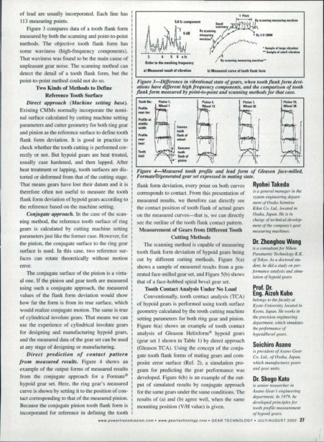
Figure 3-Difjerence ill vibrational stale oj gears, IIIlIel.' tootll,jlallkjorm de vialUms<br />
base dlfjert!flt high frequency ,componelll • alld tile comparo.'Oll 0/ tootll<br />
fll1II1c/ormmeasured by poirlt-to-poillt "",d. canllirlg mel/mas/or ,'I,al ca_I!.<br />
Pr.m.<br />
nl., tOI<br />
Pnlfl'-I!'<br />
.ifd_,<br />
·widtbl<br />
Prom.<br />
I!U!11<br />
IhRI<br />
P<strong>in</strong>iQo1.<br />
W-h •• ll<br />
of cyl<strong>in</strong>drical <strong>in</strong>volute gears. That mean we can sett<strong>in</strong>g parameters for bothr:<strong>in</strong>g gear and p<strong>in</strong>ion.<br />
use <strong>the</strong> experience of cyl<strong>in</strong>drical <strong>in</strong>volute gears Figure 6(a) hews an example of tooth contact<br />
for design<strong>in</strong>g and manufactur<strong>in</strong>g hypoidgears, analy is of Gleason Hehxform® hypoid gears<br />
and <strong>the</strong> measured data of <strong>the</strong> gear el can be used (gear et 1 shown <strong>in</strong> Table I) by direct approach<br />
at any stage of design<strong>in</strong>g or manufactur<strong>in</strong>g. (Gleason TCA). Us<strong>in</strong>g <strong>the</strong> concept of <strong>the</strong> conjuis<br />
president<br />
of Asmlo <strong>Gear</strong><br />
Direct' pred.iclioll of contact pat.tern gate tooth flank forms of mat<strong>in</strong>g gears and com- Co. ua.. of Osaka. Japan.<br />
from measured reslIlts. Figure 4 shows an po ite error surface (Ref. 2). a simulation pro- which manufactures Mears<br />
example of <strong>the</strong> output forms of measured results gram for predict<strong>in</strong>g <strong>the</strong> gear performance was and gear unhs.<br />
from <strong>the</strong> conjugate approach for a Forma!.e® developed. Figure 6(b) is an example of <strong>the</strong> out- Dr; Shogo Kato<br />
hypoidgear set. Here, <strong>the</strong> r<strong>in</strong>g gear's measured put of simulated results by conjugate approach I.r senior 1'f'.W!IJr'C'h('r ill<br />
curve i hown by sen<strong>in</strong>git to <strong>the</strong> po Won of coo- for <strong>the</strong> same gears under tile same condition. The Asalla <strong>Gear</strong>'s eIIR;t1eer;'lg<br />
department. 1/1 1979. he<br />
tact correspond<strong>in</strong>g to thaI of <strong>the</strong> measured p<strong>in</strong>ion. results of (a) and. (b) agree well, when <strong>the</strong> same<br />
lie veloped pr<strong>in</strong>ciples for<br />
Because <strong>the</strong> conjugate p<strong>in</strong>ion: tooth flank form is mount<strong>in</strong>g position (VIH valuerts given. 1001/1 profile m1.'fISIIYI.'m1'11I<br />
<strong>in</strong>corporated for reference <strong>in</strong> def<strong>in</strong><strong>in</strong>g <strong>the</strong> tooth of hypoiti gears.<br />
www.powerl,ansmlssion.com •.. W .... gfN.,rschnology.com '. GEAR TECHNOLOGY' JULY/AUGUST <strong>2002</strong> .27<br />
~nr!! __•<br />
1•• 1b<br />
".nk ,Dr<br />
wh •• r<br />
ICooe ...<br />
loath<br />
;F:...::.,,:lrltt- 'It,nk 0'<br />
pl.lo.<br />
P,<strong>in</strong>ion t,<br />
Wh •• 11]<br />
Figur:e 4-Measul'ed tooti. profill! alld teod [ormo[ Gleason jace-milled,<br />
Fiirmale@lgenerated gear set expressed ;n malill,g state.<br />
see <strong>the</strong> outl<strong>in</strong>e of <strong>the</strong> tooth flank contact pattern.<br />
Measurement of <strong>Gear</strong>s from DLfIcR!ol Tooth<br />
Cutt<strong>in</strong>g Methods<br />
The scann<strong>in</strong>g method is capable of measur<strong>in</strong>g<br />
tooth flank form deviation of hypoid gear be<strong>in</strong>g<br />
cut by different cutt<strong>in</strong>g methods, igure 5(a)<br />
shows a sample of measured results (rom a generated<br />
face-milled gear set. and Figure 5(b) shows<br />
that of a face-bobbed spiral bevelgear set.<br />
Ryohei Takedal<br />
flank form deviation, every po.<strong>in</strong>l on both curves<br />
. f is {/ general manager ill rile<br />
corresponds to contact. From this presentation or<br />
system eng<strong>in</strong>eer<strong>in</strong>g dept/rimea<br />
ured re ul • we <strong>the</strong>refore can directly see i1If'!l! (if Osako Seimil.fll<br />
<strong>the</strong> contact position of tooth flank of actual gears Kiwi Co. Ltd .. Jocml'd ill<br />
on <strong>the</strong> measured curves=that is. we can directly Osaka. Japo». HI' is ill<br />
ciJarge of technical del·elop·<br />
melll nJ <strong>the</strong> ('atfl{)(.III_~1$ sear<br />
measur<strong>in</strong>g mach<strong>in</strong>es.<br />
Dr. Zhonghou<br />
w.ang<br />
i.f a consultant for Nihon<br />
Parametric Technology I(.K.<br />
of Tokyo. As (l doctoral studau.<br />
Ire did a Sillily on perfonnance<br />
anotysis ana simu-<br />
/mimr of ttypoid Rears.<br />
Prof. Dr.<br />
Eng ..Aizoh Kl.lbol<br />
belol1gs to tht! jacullY at<br />
Kyoto Univer. iry, 1£l{'alt!d ill<br />
Kyoto. Japan. He 'l'or.b <strong>in</strong><br />
<strong>the</strong> precision eng<strong>in</strong>eerillg<br />
deportment. w/rk/l.l<strong>in</strong>rll/ares<br />
tlu: lJeifomrance of<br />
In·IJUidlbel·e/ gems.


