

Download the July/August 2002 Issue in PDF format - Gear ...
Download the July/August 2002 Issue in PDF format - Gear ...
Download the July/August 2002 Issue in PDF format - Gear ...

Create successful ePaper yourself
Turn your PDF publications into a flip-book with our unique Google optimized e-Paper software.
al·GI.....<br />
~f<br />
~lLJ<br />
'.::<br />
No,. 01 teeth:<br />
\ tll,l'll<br />
~ M':!~I.'<br />
,,~ hce Width:<br />
".lV· : 25.0mm<br />
.. P<strong>in</strong>ion Ofbet<br />
_ 5jt mill<br />
"<strong>in</strong>al •• at PLniQP<br />
:gan.raled/generated hnoid gelt<br />
p...m.<br />
r••!fiLud<br />
''li-i"'tr.<br />
" \<br />
Figure 5 Measured tooth ./klnk form of gears of different cutt<strong>in</strong>g met/JOds.<br />
Tooth contllc': pattern<br />
!Motion CUIflI8<br />
-.,..... _',L--<br />
Vill., ..IJ.~1.13 (mm)<br />
a) Direct appr,olch (Gleason TCA)<br />
Figure 6-TCA<br />
.::.,<br />
r.,l,\~~ ....<br />
1/.: ~;"<br />
'If! ~<br />
it<br />
C~ntaclP.lttem<br />
1"--- ... -<br />
! j TraR.mission Errllf<br />
j __ M~~<br />
AI. <strong>the</strong> first stage of hypoid<br />
cutt<strong>in</strong>g<br />
28 JULY/AUGUST <strong>2002</strong>· GEAR TECHNOLOGV • www.geartschnology.com' wwW.powsftransm/ss/on.com<br />
..<br />
~ liiim~':J;<br />
! u - -<br />
• --':11 !I' -, -<br />
-------'<br />
ViIl,= ..1),081'1.'13 (mm)<br />
of direct approach amI conjugaleappr:oach.<br />
.,<br />
..<br />
..<br />
..<br />
..<br />
Contac! Pattern & Plm 01ColIIId<br />
., ; II<br />
J J<br />
/"<br />
r /<br />
of F F<br />
... ..<br />
"<br />
fI Trusm'ission' Enor<br />
(Too.h Harmonics)<br />
u<br />
IJ<br />
u<br />
u<br />
u<br />
1-'<br />
.....-<br />
OJ •<br />
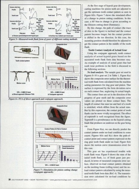
Figure "" Simuiatio.n! for pillio/l CUttilig ehang«<br />
(conjugate approacll).<br />
I<br />
gear development,<br />
mach<strong>in</strong>es for p<strong>in</strong>ion teeth are adjusted to<br />
get <strong>the</strong> optimum tooth contact pattern as seen <strong>in</strong><br />
Figure 6(b). Figure 7 shows <strong>the</strong> simulated effect<br />
of a change <strong>in</strong> p<strong>in</strong>ion cutt<strong>in</strong>g conditions. In this<br />
case, a 60' bias-<strong>in</strong> change is given accord<strong>in</strong>g to'<br />
<strong>the</strong> Gleason cutt<strong>in</strong>g sheet (Summary).<br />
By this change, <strong>the</strong> path of contact (<strong>the</strong> trace<br />
of dots <strong>in</strong> <strong>the</strong> figure) is <strong>in</strong>cl<strong>in</strong>ed and <strong>the</strong> contact<br />
pattern becomes longer, but <strong>the</strong> contact position<br />
is shifted <strong>in</strong> <strong>the</strong> toe direction .. In this case, <strong>the</strong><br />
mount<strong>in</strong>g position should <strong>the</strong>refore be adjusted to<br />
get <strong>the</strong> contact. pattern. <strong>in</strong> <strong>the</strong> middle<br />
of <strong>the</strong> moth<br />
Hank.<br />
Tooth Contact Analysis of Actual <strong>Gear</strong><br />
Us<strong>in</strong>g <strong>the</strong> conjugate approach, tooth contact<br />
analysis of actual hypcid gears based on <strong>the</strong><br />
measured tooth flank form data becomes easy.<br />
An example of analysis of acrualgears that had<br />
tooth wear problems <strong>in</strong> <strong>the</strong> field is discussed <strong>in</strong><br />
<strong>the</strong> fol1ow<strong>in</strong>g sections.<br />
No load analysis. The sample<br />
gear set used<strong>in</strong><br />
Figures 8-10 is gear set 2 il] Table 1. Figure 8(a)<br />
shows <strong>the</strong> composite error surface for <strong>the</strong> <strong>the</strong>oretical<br />
tooth flank form calculated<br />
from. <strong>the</strong> mach<strong>in</strong>e<br />
sett<strong>in</strong>g parameters for r<strong>in</strong>g gear and p<strong>in</strong>ion. That<br />
surface is expressed by <strong>the</strong> form deviation curve<br />
on each contact l<strong>in</strong>e, neglect<strong>in</strong>g its actual length.<br />
The contact l<strong>in</strong>es are set <strong>in</strong> <strong>the</strong> direction of <strong>the</strong><br />
progress of gear mesh and <strong>the</strong> composite error<br />
values are plotted on <strong>the</strong>se contact l<strong>in</strong>es. The<br />
length of contact l<strong>in</strong>e near toe and heel of a tooth<br />
is stretched, which differs from <strong>the</strong> actual state ..<br />
But by this expression, <strong>the</strong> contact po<strong>in</strong>t of tooth<br />
flanks can be more vividly recognized. The effect<br />
of toprem® is well recognized from <strong>the</strong> figure ..<br />
Toprem® is a protuberance on <strong>the</strong> hypoid cutt<strong>in</strong>g<br />
blade that produces an undercut on <strong>the</strong> gear be<strong>in</strong>g<br />
cut.<br />
FCQm Figure 8(a), we can directlypredict <strong>the</strong><br />
contact pattern under no-load conditions to some<br />
extent, Figures 8(b) and 8(c) show <strong>the</strong> path-ofcontactpe<strong>in</strong>t<br />
and contact pattem expressed on <strong>the</strong><br />
r<strong>in</strong>g gear tooth flank under no load. Figure 8Cd)<br />
shows <strong>the</strong> motion curve (transmission error) for<br />
this case,<br />
This gear set has experienced trouble with<br />
tooth flank wear. Figure '9 shows <strong>the</strong> state of <strong>the</strong><br />
<strong>in</strong>itial tooth flank, l.e. of fresh gears just produced,<br />
<strong>in</strong> terms of measured composite error surface,<br />
observed no-load contact pattern obta<strong>in</strong>ed<br />
on <strong>the</strong> mesh<strong>in</strong>g frame (roll<strong>in</strong>g tester) and<strong>the</strong> noload<br />
contact pa:ttern calculated by us<strong>in</strong>g <strong>the</strong> measured<br />
tooth flank form data (Ref. 4). The transmission<br />
error calculated for no-load conditions by


