Sacramento Surveyors Visit the NGS Airborne Gravimeter - CLSA
Sacramento Surveyors Visit the NGS Airborne Gravimeter - CLSA
Sacramento Surveyors Visit the NGS Airborne Gravimeter - CLSA

You also want an ePaper? Increase the reach of your titles
YUMPU automatically turns print PDFs into web optimized ePapers that Google loves.
Continued from previous page<br />
Relative vs. Absolute<br />
Your local plane-surveyed topographic survey probably<br />
starts on an assumed grid location of N 5,000, E 5,000. All<br />
<strong>the</strong> data points located are relative to that origin using <strong>the</strong><br />
latitudes/departures derived from angle and distance. Your<br />
grid origin coordinates really don’t matter in your plane system.<br />
If you started at N 10,000, E 10,000, your topographic<br />
survey would still show features in <strong>the</strong>ir same relative<br />
position.<br />
This is fundamentally true of GPS baselines as well. A<br />
“baseline”, or “vector”, between two receivers is derived<br />
from <strong>the</strong> differences of <strong>the</strong>ir 3D coordinates, but with much<br />
larger (and possibly negative) numbers than your plane<br />
topographic survey. This is <strong>the</strong> “relative” positional relationship.<br />
The “absolute” position of ei<strong>the</strong>r of <strong>the</strong>se two<br />
receivers comes from attaching one end of <strong>the</strong> vector to a<br />
known position on a particular datum on a particular date.<br />
The baseline or 3D difference from one point having a<br />
known “absolute” position is used to compute an<br />
“absolute” position of <strong>the</strong> o<strong>the</strong>r. But <strong>the</strong> concept of<br />
absolute is a misnomer, in that <strong>the</strong>re is no absolute position<br />
on our forever changing earth. Absolute really means fixed<br />
to a datum on a specific date, allowing reference to that<br />
position.<br />
GPS SURVEYS<br />
Types of Surveys<br />
Surveying with GPS can employ several techniques:<br />
static, rapid static, kinematic and real time kinematic (RTK).<br />
We will be considering <strong>the</strong> first two – static and rapid static<br />
– since <strong>the</strong>se techniques require setting a receiver on a<br />
survey point, collecting satellite data for an appropriate<br />
amount of time and using data collected at a second<br />
receiver (ei<strong>the</strong>r yours or a CGPSS) to compute a “baseline”<br />
or “vector” (<strong>the</strong> relative position between <strong>the</strong> two receivers).<br />
Using <strong>the</strong> data available from a CGPSS, it is possible to<br />
employ a single receiver and <strong>the</strong> concurrent CGPSS data to<br />
compute a baseline between <strong>the</strong> two receivers in a “differential”<br />
process. But don’t mistake this differential process<br />
for “DGPS”, which uses a completely different system of<br />
providing real time differences for your receiver.<br />
GPS Survey Configurations<br />
There are two types of surveys where <strong>the</strong> procedures<br />
discussed in this article might be used. The first type would<br />
be when doing a control survey. One variety of control survey<br />
is a radial survey where one receiver is a “Base” station<br />
that runs continuously during <strong>the</strong> survey at one point, while<br />
<strong>the</strong> o<strong>the</strong>r receiver is moved to all <strong>the</strong> o<strong>the</strong>r points being surveyed.<br />
The result is radial baselines emanating from one<br />
point. Ano<strong>the</strong>r variation of control survey is a traverse type<br />
survey, where <strong>the</strong> receivers are moved from point to point,<br />
not unlike a total station traverse. The second type of survey<br />
is an RTK survey where you need to get good relative<br />
Spring 2011<br />
positions. Your base station for <strong>the</strong> RTK survey can also be<br />
collecting data for post processing while <strong>the</strong> RTK survey is<br />
being done which will allow you to later place <strong>the</strong> RTK survey<br />
in a geodetic framework once you know <strong>the</strong> base<br />
receiver’s “absolute” position.<br />
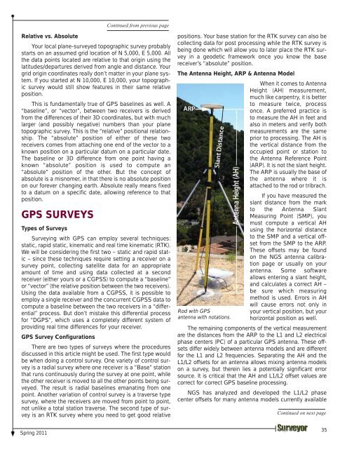
The Antenna Height, ARP & Antenna Model<br />
When it comes to Antenna<br />
Height (AH) measurement,<br />
much like carpentry, it is better<br />
to measure twice, process<br />
once. A preferred practice is<br />
to measure <strong>the</strong> AH in feet and<br />
also in meters and verify both<br />
measurements are <strong>the</strong> same<br />
prior to processing. The AH is<br />
<strong>the</strong> vertical distance from <strong>the</strong><br />
occupied point or station to<br />
<strong>the</strong> Antenna Reference Point<br />
(ARP). It is not <strong>the</strong> slant height.<br />
The ARP is usually <strong>the</strong> base of<br />
<strong>the</strong> antenna where it is<br />
attached to <strong>the</strong> rod or tribrach.<br />
Rod with GPS<br />
antenna with notations.<br />
If you have measured <strong>the</strong><br />
slant distance from <strong>the</strong> mark<br />
to <strong>the</strong> Antenna Slant<br />
Measuring Point (SMP), you<br />
must compute a vertical AH<br />
using <strong>the</strong> horizontal distance<br />
to <strong>the</strong> SMP and a vertical offset<br />
from <strong>the</strong> SMP to <strong>the</strong> ARP.<br />
These offsets may be found<br />
on <strong>the</strong> <strong>NGS</strong> antenna calibration<br />
page or usually on your<br />
antenna. Some software<br />
allows entering a slant height,<br />
and calculates a correct AH –<br />
be sure which measuring<br />
method is used. Errors in AH<br />
will cause errors not only in<br />
your vertical position, but your<br />
horizontal position as well.<br />
The remaining components of <strong>the</strong> vertical measurement<br />
are <strong>the</strong> distances from <strong>the</strong> ARP to <strong>the</strong> L1 and L2 electrical<br />
phase centers (PC) of a particular GPS antenna. These offsets<br />
differ widely between antenna models and are different<br />
for <strong>the</strong> L1 and L2 frequencies. Separating <strong>the</strong> AH and <strong>the</strong><br />
L1/L2 offsets for an antenna allows mixing antenna models<br />
on a survey, but <strong>the</strong>rein lies a potentially significant error<br />
source. It is critical that <strong>the</strong> AH and L1/L2 offset values are<br />
correct for correct GPS baseline processing.<br />
<strong>NGS</strong> has analyzed and developed <strong>the</strong> L1/L2 phase<br />
center offsets for many antenna models currently available<br />
Continued on next page<br />
35