- Page 1 and 2:
User Manual K1297-G20 Monitor Proto
- Page 3:
WARRANTY Tektronix warrants that th
- Page 6 and 7:
Contents Appendix D: Windows XPe Tr
- Page 8 and 9:
General Safety Summary Use Proper A
- Page 10 and 11:
General Safety Summary Terms on the
- Page 12 and 13:
Service Safety Summary viii K1297-G
- Page 14 and 15:
Preface K1297 and K1297 Compact. Th
- Page 16 and 17:
Preface Prerequisites You should ha
- Page 18 and 19:
Preface About the User Manual The U
- Page 20 and 21:
Preface Contacting Tektronix Addres
- Page 22 and 23:
Getting Started Device Description
- Page 24 and 25:
Getting Started 3. Take the cable o
- Page 26 and 27:
Getting Started 3. Fold the device
- Page 28 and 29:
Getting Started 4. Push the front c
- Page 30 and 31:
Getting Started Connecting an Exter
- Page 32 and 33:
Getting Started Operating only the
- Page 34 and 35:
Getting Started Before writing a
- Page 36 and 37:
Getting Started K1297 Compact. For
- Page 38 and 39:
Getting Started Exchanging Measurin
- Page 40 and 41:
Getting Started The following color
- Page 42 and 43:
Getting Started Setting the VME Bus
- Page 44 and 45:
Getting Started K1297. Make sure th
- Page 46 and 47:
Getting Started Removing Modules If
- Page 48 and 49:
Getting Started Switching on the De
- Page 50 and 51:
Getting Started K1297-G20 Monitor A
- Page 52 and 53:
Getting Started Measurement Scenari
- Page 54 and 55:
Getting Started Software Installati
- Page 56 and 57:
Getting Started Pre-Installation Ch
- Page 58 and 59:
Getting Started Installation of Add
- Page 60 and 61:
Getting Started 5. In the product s
- Page 62 and 63:
Getting Started Back Up the Softwar
- Page 64 and 65:
Getting Started 5. In the product s
- Page 66 and 67:
Getting Started Operating System Th
- Page 68 and 69:
Getting Started Autologon Account.
- Page 70 and 71:
Getting Started Ethernet Connection
- Page 72 and 73:
Getting Started Remote Operation Re
- Page 74 and 75:
Getting Started Connecting Peripher
- Page 76 and 77:
Examples Online Monitoring in a Net
- Page 78 and 79:
Examples NOTE. The data line has no
- Page 80 and 81: Examples The right side of the wind
- Page 82 and 83: Examples The data in each view is c
- Page 84 and 85: Examples Recording and Reviewing Mo
- Page 86 and 87: Examples Press Browse, if you want
- Page 88 and 89: Examples Reviewing Recorded Data Pr
- Page 90 and 91: Examples 4. If you want to filter t
- Page 92 and 93: Examples Preliminary Steps The Prot
- Page 94 and 95: Examples 3. Select the protocol fro
- Page 96 and 97: Examples 10. Click Start to start C
- Page 98 and 99: Examples Examples. The number you w
- Page 100 and 101: Examples 88 K1297-G20 Monitor User
- Page 102 and 103: Appendix A: Interfaces System Unit
- Page 104 and 105: Appendix A: Interfaces Reset. To re
- Page 106 and 107: Appendix A: Interfaces Additional K
- Page 108 and 109: Appendix A: Interfaces Parallel Int
- Page 110 and 111: Appendix A: Interfaces Ethernet BNC
- Page 112 and 113: Appendix A: Interfaces External Mon
- Page 114 and 115: Appendix A: Interfaces USB (Univers
- Page 116 and 117: Appendix A: Interfaces The synchron
- Page 118 and 119: Appendix A: Interfaces Table A-12:
- Page 120 and 121: Appendix A: Interfaces PC Card Slot
- Page 122 and 123: Appendix A: Interfaces Figure A-1:
- Page 124 and 125: Appendix A: Interfaces Working With
- Page 126 and 127: Appendix A: Interfaces In addition
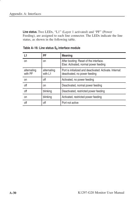
- Page 128 and 129: Appendix A: Interfaces 8 1 S 0 4 1
- Page 132 and 133: Appendix A: Interfaces U 2B1Q Inter
- Page 134 and 135: Appendix A: Interfaces Pin Assignme
- Page 136 and 137: Appendix A: Interfaces B Channel Ac
- Page 138 and 139: Appendix A: Interfaces V./X. Board
- Page 140 and 141: Appendix A: Interfaces Each termina
- Page 142 and 143: Appendix A: Interfaces Table A-25:
- Page 144 and 145: Appendix A: Interfaces Table A-26:
- Page 146 and 147: Appendix A: Interfaces Table A-27:
- Page 148 and 149: Appendix A: Interfaces The followin
- Page 150 and 151: Appendix A: Interfaces 9-pin D-Sub
- Page 152 and 153: Appendix A: Interfaces 8 1 Ethernet
- Page 154 and 155: Appendix A: Interfaces The two swit
- Page 156 and 157: Appendix A: Interfaces Defining CPU
- Page 158 and 159: Appendix A: Interfaces A-58 K1297-G
- Page 160 and 161: Appendix B: Keyboard Alphanumeric K
- Page 162 and 163: Appendix B: Keyboard Table B-1: Spe
- Page 164 and 165: Appendix B: Keyboard Language Suppo
- Page 166 and 167: Appendix B: Keyboard Switching the
- Page 168 and 169: Appendix B: Keyboard Deactivating a
- Page 170 and 171: Appendix B: Keyboard B-12 K1297-G20
- Page 172 and 173: Appendix C: Specifications Table C-
- Page 174 and 175: Appendix C: Specifications Table C-
- Page 176 and 177: Appendix C: Specifications Table C-
- Page 178 and 179: Appendix C: Specifications CAUTION.
- Page 180 and 181:
Appendix D: Windows XPe Troubleshoo
- Page 182 and 183:
Appendix D: Windows XPe Troubleshoo
- Page 184 and 185:
Appendix D: Windows XPe Troubleshoo
- Page 186 and 187:
Appendix D: Windows XPe Troubleshoo
- Page 188 and 189:
Appendix D: Windows XPe Troubleshoo
- Page 190 and 191:
Appendix D: Windows XPe Troubleshoo
- Page 192 and 193:
Abbreviations HLR Home location reg
- Page 194 and 195:
Abbreviations SMS Short message ser
- Page 196 and 197:
Index E E1/DS1 Monitoring Board, A-
- Page 198:
Index R Record Viewer, 76 Recording