Vulcraft Steel Roof and Floor Deck Catalog - University of Maryland ...
Vulcraft Steel Roof and Floor Deck Catalog - University of Maryland ...
Vulcraft Steel Roof and Floor Deck Catalog - University of Maryland ...
- No tags were found...
Create successful ePaper yourself
Turn your PDF publications into a flip-book with our unique Google optimized e-Paper software.
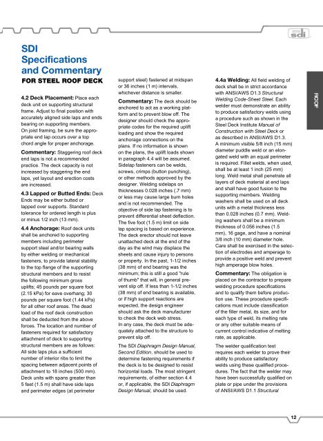
SDI<br />
Specifications<br />
<strong>and</strong> Commentary<br />
FOR STEEL ROOF DECK<br />
4.2 <strong>Deck</strong> Placement: Place each<br />
deck unit on supporting structural<br />
frame. Adjust to final position with<br />
accurately aligned side laps <strong>and</strong> ends<br />
bearing on supporting members.<br />
On joist framing, be sure the appropriate<br />
end lap occurs over a top<br />
chord angle for proper anchorage.<br />
Commentary: Staggering ro<strong>of</strong> deck<br />
end laps is not a recommended<br />
practice. The deck capacity is not<br />
increased by staggering the end<br />
laps, yet layout <strong>and</strong> erection costs<br />
are increased.<br />
4.3 Lapped or Butted Ends: <strong>Deck</strong><br />
Ends may be either butted or<br />
lapped over supports. St<strong>and</strong>ard<br />
tolerance for ordered length is plus<br />
or minus 1/2 inch (13 mm).<br />
4.4 Anchorage: <strong>Ro<strong>of</strong></strong> deck units<br />
shall be anchored to supporting<br />
members including perimeter<br />
support steel <strong>and</strong>/or bearing walls<br />
by either welding or mechanical<br />
fasteners, to provide lateral stability<br />
to the top flange <strong>of</strong> the supporting<br />
structural members <strong>and</strong> to resist<br />
the following minimum gross<br />
uplifts; 45 pounds per square foot<br />
(2.15 kPa) for eave overhang; 30<br />
pounds per square foot (1.44 kPa)<br />
for all other ro<strong>of</strong> areas. The dead<br />
load <strong>of</strong> the ro<strong>of</strong> deck construction<br />
shall be deducted from the above<br />
forces. The location <strong>and</strong> number <strong>of</strong><br />
fasteners required for satisfactory<br />
attachment <strong>of</strong> deck to supporting<br />
structural members are as follows:<br />
All side laps plus a sufficient<br />
number <strong>of</strong> interior ribs to limit the<br />
spacing between adjacent points <strong>of</strong><br />
attachment to 18 inches (500 mm).<br />
<strong>Deck</strong> units with spans greater than<br />
5 feet (1.5 m) shall have side laps<br />
<strong>and</strong> perimeter edges (at perimeter<br />
support steel) fastened at midspan<br />
or 36 inches (1 m) intervals,<br />
whichever distance is smaller.<br />
Commentary: The deck should be<br />
anchored to act as a working platform<br />
<strong>and</strong> to prevent blow <strong>of</strong>f. The<br />
designer should check the appropriate<br />
codes for the required uplift<br />
loading <strong>and</strong> show the required<br />
anchorage connections on the<br />
plans. If no information is shown<br />
on the plans, the uplift loads shown<br />
in paragraph 4.4 will be assumed.<br />
Sidelap fasteners can be welds,<br />
screws, crimps (button punching),<br />
or other methods approved by the<br />
designer. Welding sidelaps on<br />
thicknesses 0.028 inches (.7 mm)<br />
or less may cause large burn holes<br />
<strong>and</strong> is not recommended. The<br />
objective <strong>of</strong> side lap fastening is to<br />
prevent differential sheet deflection.<br />
The five foot (1.5 m) limit on side<br />
lap spacing is based on experience.<br />
The deck erector should not leave<br />
unattached deck at the end <strong>of</strong> the<br />
day as the wind may displace the<br />
sheets <strong>and</strong> cause injury to persons<br />
or property. In the past, 1-1/2 inches<br />
(38 mm) <strong>of</strong> end bearing was the<br />
minimum; this is still a good "rule<br />
<strong>of</strong> thumb" that will, in general prevent<br />
slip <strong>of</strong>f. If less than 1-1/2 inches<br />
(38 mm) <strong>of</strong> end bearing is available,<br />
or if high support reactions are<br />
expected, the design engineer<br />
should ask the deck manufacturer<br />
to check the deck web stress.<br />
In any case, the deck must be adequately<br />
attached to the structure to<br />
prevent slip <strong>of</strong>f.<br />
The SDI Diaphragm Design Manual,<br />
Second Edition, should be used to<br />
determine fastening requirements if<br />
the deck is to be designed to resist<br />
horizontal loads. The most stringent<br />
requirements, <strong>of</strong> either section 4.4<br />
or, if applicable, the SDI Diaphragm<br />
Design Manual, should be used.<br />
4.4a Welding: All field welding <strong>of</strong><br />
deck shall be in strict accordance<br />
with ANSI/AWS D1.3 Structural<br />
Welding Code-Sheet <strong>Steel</strong>. Each<br />
welder must demonstrate an ability<br />
to produce satisfactory welds using<br />
a procedure such as shown in the<br />
<strong>Steel</strong> <strong>Deck</strong> Institute Manual <strong>of</strong><br />
Construction with <strong>Steel</strong> <strong>Deck</strong> or<br />
as described in ANSI/AWS D1.3.<br />
A minimum visible 5/8 inch (15 mm)<br />
diameter puddle weld or an elongated<br />
weld with an equal perimeter<br />
is required. Fillet welds, when used,<br />
shall be at least 1 inch (25 mm)<br />
long. Weld metal shall penetrate all<br />
layers <strong>of</strong> deck material at end laps<br />
<strong>and</strong> shall have good fusion to the<br />
supporting members. Welding<br />
washers shall be used on all deck<br />
units with a metal thickness less<br />
than 0.028 inches (0.7 mm). Welding<br />
washers shall be a minimum<br />
thickness <strong>of</strong> 0.056 inches (1.5<br />
mm), 16 gage, <strong>and</strong> have a nominal<br />
3/8 inch (10 mm) diameter hole.<br />
Care shall be exercised in the selection<br />
<strong>of</strong> electrodes <strong>and</strong> amperage to<br />
provide a positive weld <strong>and</strong> prevent<br />
high amperage blow holes.<br />
Commentary: The obligation is<br />
placed on the contractor to prepare<br />
welding procedure specifications<br />
<strong>and</strong> to qualify them before production<br />
use. These procedure specifications<br />
must include classification<br />
<strong>of</strong> the filler metal, its size, <strong>and</strong> for<br />
each type <strong>of</strong> weld, its melting rate<br />
or any other suitable means <strong>of</strong><br />
current control indicative <strong>of</strong> melting<br />
rate, as applicable.<br />
The welder qualification test<br />
requires each welder to prove their<br />
ability to produce satisfactory<br />
welds using these qualified procedures.<br />
The fact that the welder may<br />
have been successfully qualified on<br />
plate or pipe under the provisions<br />
<strong>of</strong> ANSI/AWS D1.1 Structural<br />
12


