Vulcraft Steel Roof and Floor Deck Catalog - University of Maryland ...
Vulcraft Steel Roof and Floor Deck Catalog - University of Maryland ...
Vulcraft Steel Roof and Floor Deck Catalog - University of Maryland ...
- No tags were found...
Create successful ePaper yourself
Turn your PDF publications into a flip-book with our unique Google optimized e-Paper software.
SDI<br />
Specifications<br />
<strong>and</strong> Commentary<br />
FOR COMPOSITE<br />
FLOOR DECK<br />
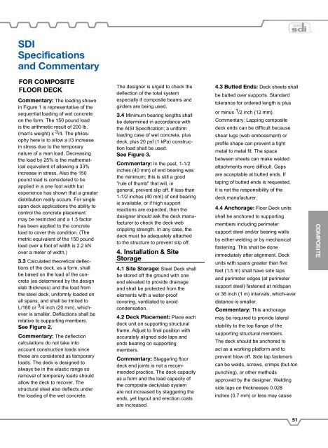
Commentary: The loading shown<br />
in Figure 1 is representative <strong>of</strong> the<br />
sequential loading <strong>of</strong> wet concrete<br />
on the form. The 150 pound load<br />
is the arithmetic result <strong>of</strong> 200 lb.<br />
(man's weight) x 3 /4. The philosophy<br />
here is to allow a l/3 increase<br />
in stress due to the temporary<br />
nature <strong>of</strong> a man load. Decreasing<br />
the load by 25% is the mathematical<br />
equivalent <strong>of</strong> allowing a 33%<br />
increase in stress. Also the 150<br />
pound load is considered to be<br />
applied in a one foot width but<br />
experience has shown that a greater<br />
distribution really occurs. For single<br />
span deck applications the ability to<br />
control the concrete placement<br />
may be restricted <strong>and</strong> a 1.5 factor<br />
has been applied to the concrete<br />
load to cover this condition. (The<br />
metric equivalent <strong>of</strong> the 150 pound<br />
load over a foot <strong>of</strong> width is 2.2 kN<br />
over a meter <strong>of</strong> width.)<br />
3.3 Calculated theoretical deflections<br />
<strong>of</strong> the deck, as a form, shall<br />
be based on the load <strong>of</strong> the concrete<br />
(as determined by the design<br />
slab thickness) <strong>and</strong> the load from<br />
the steel deck, uniformly loaded on<br />
all spans, <strong>and</strong> shall be limited to<br />
L/180 or 3 /4 inch (20 mm), whichever<br />
is smaller. Deflections shall be<br />
relative to supporting members.<br />
See Figure 2.<br />
Commentary: The deflection<br />
calculations do not take into<br />
account construction loads since<br />
these are considered as temporary<br />
loads. The deck is designed to<br />
always be in the elastic range so<br />
removal <strong>of</strong> temporary loads should<br />
allow the deck to recover. The<br />
structural steel also deflects under<br />
the loading <strong>of</strong> the wet concrete.<br />
The designer is urged to check the<br />
deflection <strong>of</strong> the total system<br />
especially if composite beams <strong>and</strong><br />
girders are being used.<br />
3.4 Minimum bearing lengths shall<br />
be determined in accordance with<br />
the AISI Specification; a uniform<br />
loading case <strong>of</strong> wet concrete, plus<br />
deck, plus 20 psf (1 kPa) construction<br />
load shall be used.<br />
See Figure 3.<br />
Commentary: In the past, 1-1/2<br />
inches (40 mm) <strong>of</strong> end bearing was<br />
the minimum; this is still a good<br />
"rule <strong>of</strong> thumb" that will, in<br />
general, prevent slip <strong>of</strong>f. If less than<br />
1-1/2 inches (40 mm) <strong>of</strong> end bearing<br />
is available, or if high support<br />
reactions are expected, then the<br />
designer should ask the deck manufacturer<br />
to check the deck web<br />
crippling strength. In any case, the<br />
deck must be adequately attached<br />
to the structure to prevent slip <strong>of</strong>f.<br />
4. Installation & Site<br />
Storage<br />
4.1 Site Storage: <strong>Steel</strong> <strong>Deck</strong> shall<br />
be stored <strong>of</strong>f the ground with one<br />
end elevated to provide drainage<br />
<strong>and</strong> shall be protected from the<br />
elements with a water-pro<strong>of</strong><br />
covering, ventilated to avoid<br />
condensation.<br />
4.2 <strong>Deck</strong> Placement: Place each<br />
deck unit on supporting structural<br />
frame. Adjust to final position with<br />
accurately aligned side laps <strong>and</strong><br />
ends bearing on supporting<br />
members.<br />
Commentary: Staggering floor<br />
deck end joints is not a recommended<br />
practice. The deck capacity<br />
as a form <strong>and</strong> the load capacity <strong>of</strong><br />
the composite deck/slab system<br />
are not increased by staggering the<br />
ends, yet layout <strong>and</strong> erection costs<br />
are increased.<br />
4.3 Butted Ends: <strong>Deck</strong> sheets shall<br />
be butted over supports. St<strong>and</strong>ard<br />
tolerance for ordered length is plus<br />
or minus 1 /2 inch (12 mm).<br />
Commentary: Lapping composite<br />
deck ends can be difficult because<br />
shear lugs (web embossment) or<br />
pr<strong>of</strong>ile shape can prevent a tight<br />
metal to metal fit. The space<br />
between sheets can make welded<br />
attachments more difficult. Gaps<br />
are acceptable at butted ends. If<br />
taping <strong>of</strong> butted ends is requested,<br />
it is not the responsibility <strong>of</strong> the<br />
deck manufacturer.<br />
4.4 Anchorage: <strong>Floor</strong> <strong>Deck</strong> units<br />
shall be anchored to supporting<br />
members including perimeter<br />
support steel <strong>and</strong>/or bearing walls<br />
by either welding or by mechanical<br />
fastening. This shall be done<br />
immediately after alignment. <strong>Deck</strong><br />
units with spans greater than five<br />
feet (1.5 m) shall have side laps<br />
<strong>and</strong> perimeter edges (at perimeter<br />
support steel) fastened at midspan<br />
or 36 inch (1 m) intervals, which-ever<br />
distance is smaller.<br />
Commentary: This anchorage<br />
may be required to provide lateral<br />
stability to the top flange <strong>of</strong> the<br />
supporting structural members.<br />
The deck should be anchored to<br />
act as a working platform <strong>and</strong> to<br />
prevent blow <strong>of</strong>f. Side lap fasteners<br />
can be welds, screws, crimps (but-ton<br />
punching), or other methods<br />
approved by the designer. Welding<br />
side laps on thicknesses 0.028<br />
inches (0.7 mm) or less may cause<br />
51


