Vulcraft Steel Roof and Floor Deck Catalog - University of Maryland ...
Vulcraft Steel Roof and Floor Deck Catalog - University of Maryland ...
Vulcraft Steel Roof and Floor Deck Catalog - University of Maryland ...
- No tags were found...
Create successful ePaper yourself
Turn your PDF publications into a flip-book with our unique Google optimized e-Paper software.
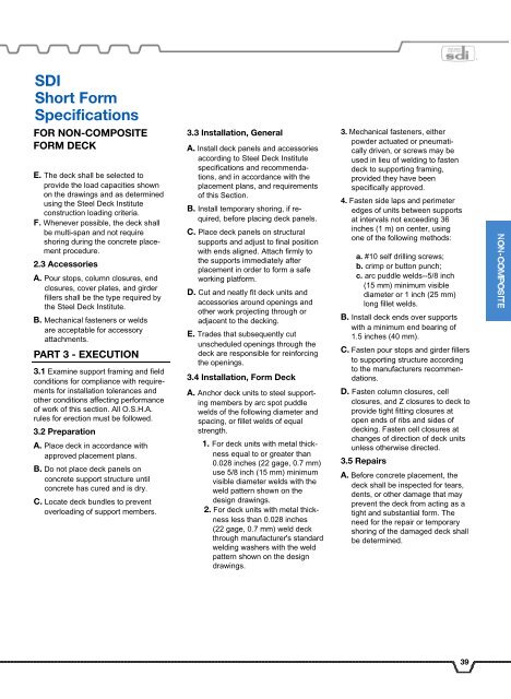
SDI<br />
Short Form<br />
Specifications<br />
FOR NON-COMPOSITE<br />
FORM DECK<br />
E. The deck shall be selected to<br />
provide the load capacities shown<br />
on the drawings <strong>and</strong> as determined<br />
using the <strong>Steel</strong> <strong>Deck</strong> Institute<br />
construction loading criteria.<br />
F. Whenever possible, the deck shall<br />
be multi-span <strong>and</strong> not require<br />
shoring during the concrete placement<br />
procedure.<br />
2.3 Accessories<br />
A. Pour stops, column closures, end<br />
closures, cover plates, <strong>and</strong> girder<br />
fillers shall be the type required by<br />
the <strong>Steel</strong> <strong>Deck</strong> Institute.<br />
B. Mechanical fasteners or welds<br />
are acceptable for accessory<br />
attachments.<br />
PART 3 - EXECUTION<br />
3.1 Examine support framing <strong>and</strong> field<br />
conditions for compliance with requirements<br />
for installation tolerances <strong>and</strong><br />
other conditions affecting performance<br />
<strong>of</strong> work <strong>of</strong> this section. All O.S.H.A.<br />
rules for erection must be followed.<br />
3.2 Preparation<br />
A. Place deck in accordance with<br />
approved placement plans.<br />
B. Do not place deck panels on<br />
concrete support structure until<br />
concrete has cured <strong>and</strong> is dry.<br />
C. Locate deck bundles to prevent<br />
overloading <strong>of</strong> support members.<br />
3.3 Installation, General<br />
A. Install deck panels <strong>and</strong> accessories<br />
according to <strong>Steel</strong> <strong>Deck</strong> Institute<br />
specifications <strong>and</strong> recommendations,<br />
<strong>and</strong> in accordance with the<br />
placement plans, <strong>and</strong> requirements<br />
<strong>of</strong> this Section.<br />
B. Install temporary shoring, if required,<br />
before placing deck panels.<br />
C. Place deck panels on structural<br />
supports <strong>and</strong> adjust to final position<br />
with ends aligned. Attach firmly to<br />
the supports immediately after<br />
placement in order to form a safe<br />
working platform.<br />
D. Cut <strong>and</strong> neatly fit deck units <strong>and</strong><br />
accessories around openings <strong>and</strong><br />
other work projecting through or<br />
adjacent to the decking.<br />
E. Trades that subsequently cut<br />
unscheduled openings through the<br />
deck are responsible for reinforcing<br />
the openings.<br />
3.4 Installation, Form <strong>Deck</strong><br />
A. Anchor deck units to steel supporting<br />
members by arc spot puddle<br />
welds <strong>of</strong> the following diameter <strong>and</strong><br />
spacing, or fillet welds <strong>of</strong> equal<br />
strength.<br />
1. For deck units with metal thickness<br />
equal to or greater than<br />
0.028 inches (22 gage, 0.7 mm)<br />
use 5/8 inch (15 mm) minimum<br />
visible diameter welds with the<br />
weld pattern shown on the<br />
design drawings.<br />
2. For deck units with metal thickness<br />
less than 0.028 inches<br />
(22 gage, 0.7 mm) weld deck<br />
through manufacturer's st<strong>and</strong>ard<br />
welding washers with the weld<br />
pattern shown on the design<br />
drawings.<br />
3. Mechanical fasteners, either<br />
powder actuated or pneumatically<br />
driven, or screws may be<br />
used in lieu <strong>of</strong> welding to fasten<br />
deck to supporting framing,<br />
provided they have been<br />
specifically approved.<br />
4. Fasten side laps <strong>and</strong> perimeter<br />
edges <strong>of</strong> units between supports<br />
at intervals not exceeding 36<br />
inches (1 m) on center, using<br />
one <strong>of</strong> the following methods:<br />
a. #10 self drilling screws;<br />
b. crimp or button punch;<br />
c. arc puddle welds--5/8 inch<br />
(15 mm) minimum visible<br />
diameter or 1 inch (25 mm)<br />
long fillet welds.<br />
B. Install deck ends over supports<br />
with a minimum end bearing <strong>of</strong><br />
1.5 inches (40 mm).<br />
C. Fasten pour stops <strong>and</strong> girder fillers<br />
to supporting structure according<br />
to the manufacturers recommendations.<br />
D. Fasten column closures, cell<br />
closures, <strong>and</strong> Z closures to deck to<br />
provide tight fitting closures at<br />
open ends <strong>of</strong> ribs <strong>and</strong> sides <strong>of</strong><br />
decking. Fasten cell closures at<br />
changes <strong>of</strong> direction <strong>of</strong> deck units<br />
unless otherwise directed.<br />
3.5 Repairs<br />
A. Before concrete placement, the<br />
deck shall be inspected for tears,<br />
dents, or other damage that may<br />
prevent the deck from acting as a<br />
tight <strong>and</strong> substantial form. The<br />
need for the repair or temporary<br />
shoring <strong>of</strong> the damaged deck shall<br />
be determined.<br />
39


