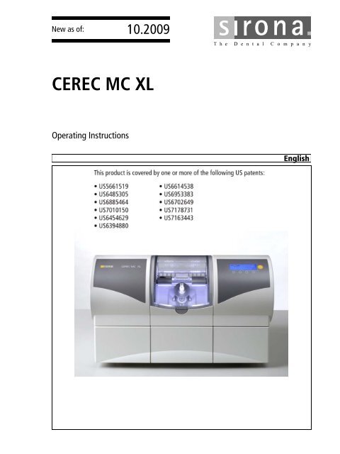
CEREC MC XL - MEDIPRO
CEREC MC XL - MEDIPRO
CEREC MC XL - MEDIPRO
You also want an ePaper? Increase the reach of your titles
YUMPU automatically turns print PDFs into web optimized ePapers that Google loves.
kÉï=~ë=çÑW==<br />
NMKOMMV<br />
`bob`=j`=ui<br />
léÉê~íáåÖ=fåëíêìÅíáçåë<br />
båÖäáëÜ
Contents<br />
Sirona Dental Systems GmbH<br />
Operating Instructions <strong>CEREC</strong> <strong>MC</strong> <strong>XL</strong><br />
Contents<br />
1 Dear Customer, ............................................................................................ 5<br />
2 General information ...................................................................................... 6<br />
2.1 Structure of the documents .............................................................. 6<br />
2.2 Note PC / Acquisition Unit ................................................................ 6<br />
2.3 Warranty ........................................................................................... 7<br />
3 General description ...................................................................................... 8<br />
3.1 Certification ...................................................................................... 8<br />
3.2 Intended use .................................................................................... 8<br />
4 Safety ........................................................................................................... 9<br />
4.1 Basic safety information ................................................................... 9<br />
4.1.1 Prerequisites ........................................................................ 9<br />
4.1.2 Maintenance and repair ....................................................... 9<br />
4.1.3 Modifications of the unit ....................................................... 9<br />
4.1.4 Accessories.......................................................................... 9<br />
4.2 Milling unit ........................................................................................ 10<br />
4.2.1 Safety information for the scanner (option) .......................... 10<br />
4.2.2 Milling chamber door open during the milling operation....... 11<br />
4.3 Wireless phone interference with equipment ................................... 11<br />
4.4 Disturbance of data transmission ..................................................... 11<br />
5 Installation and startup ................................................................................. 12<br />
5.1 Transport and unpacking ................................................................. 12<br />
5.2 Disposal of packaging materials ...................................................... 12<br />
5.3 Installation site ................................................................................. 12<br />
5.3.1 Only with integrated scanner (option) .................................. 13<br />
5.4 Initial startup ..................................................................................... 13<br />
5.4.1 Functional elements ............................................................. 14<br />
5.4.2 Display description ............................................................... 16<br />
5.4.3 Lighting of the milling chamber ............................................ 16<br />
5.4.4 Inserting the milling chamber sieve...................................... 17<br />
5.4.5 Installation ............................................................................ 17<br />
5.4.6 Filling the water tank ............................................................ 21<br />
5.4.7 Switching the unit ON and OFF ........................................... 22<br />
5.5 Repacking ........................................................................................ 23<br />
61 46 885 D 3439<br />
2 D 3439.201.02.11.02 10.2009
Sirona Dental Systems GmbH<br />
Operating Instructions <strong>CEREC</strong> <strong>MC</strong> <strong>XL</strong><br />
Contents<br />
5.6 Scope of supply ................................................................................ 23<br />
5.7 Storage ............................................................................................. 23<br />
6 Operation...................................................................................................... 24<br />
6.1 Setting the acquisition unit to scanner (onl with integrated scanner) 24<br />
6.2 Calibrating the unit ........................................................................... 24<br />
6.2.1 Calibrating the milling unit .................................................... 25<br />
6.2.2 Calibrating the scanner (only with integrated scanner) ........ 27<br />
6.3 Starting the scanning process (only with integrated scanner) .......... 29<br />
6.4 Start the milling process ................................................................... 30<br />
6.5 Preparing optical scanning (only with integrated scanner) ............... 32<br />
6.5.1 Information on preparing models for implants ...................... 32<br />
6.5.2 Creating a model .................................................................. 33<br />
6.5.3 Preparing for scanning of the veneer model ........................ 34<br />
6.6 Using the manual block clamp ......................................................... 35<br />
7 Maintenance ................................................................................................. 37<br />
7.1 Changing the water .......................................................................... 38<br />
7.1.1 General information.............................................................. 38<br />
7.1.2 Changing the water .............................................................. 39<br />
7.2 Milling instruments ............................................................................ 40<br />
7.2.1 Overview of materials and milling instruments ..................... 40<br />
7.2.2 Changing milling instruments (burs)..................................... 41<br />
7.3 Care and cleaning agents ................................................................ 42<br />
7.4 Cleaning surfaces ............................................................................. 43<br />
7.4.1 Disinfecting........................................................................... 43<br />
7.4.2 Protection against medicaments .......................................... 43<br />
7.4.3 Cleaning ............................................................................... 43<br />
7.5 Replacing the main fuses ................................................................. 44<br />
7.6 Changing the filter ............................................................................ 45<br />
7.7 Removing water from the unit .......................................................... 46<br />
7.8 Using the tank cap opener ............................................................... 46<br />
båÖäáëÜ<br />
8 Technical description.................................................................................... 48<br />
8.1 System requirements ....................................................................... 48<br />
8.2 Milling unit ........................................................................................ 48<br />
8.2.1 General technical description ............................................... 48<br />
8.2.2 Technical data ...................................................................... 49<br />
8.2.3 Scanner for optical measurement of the preparation (option) 50<br />
8.2.4 Controller board.................................................................... 50<br />
61 46 885 D 3439<br />
D 3439.201.02.11.02 10.2009 3
Contents<br />
Sirona Dental Systems GmbH<br />
Operating Instructions <strong>CEREC</strong> <strong>MC</strong> <strong>XL</strong><br />
9 Disposal........................................................................................................ 51<br />
Index............................................................................................................. 52<br />
61 46 885 D 3439<br />
4 D 3439.201.02.11.02 10.2009
Sirona Dental Systems GmbH<br />
Operating Instructions <strong>CEREC</strong> <strong>MC</strong> <strong>XL</strong><br />
1 Dear Customer,<br />
1 Dear Customer,<br />
Thank you for purchasing your <strong>CEREC</strong> <strong>MC</strong> <strong>XL</strong> ® from Sirona.<br />
This device enables you to produce dental restorations, e.g. from ceramic<br />
material with a natural appearance (CEramic REConstruction).<br />
Improper use and handling can create hazards and cause damage. Please<br />
read and follow these operating instructions carefully and Always keep them<br />
within easy reach.<br />
To prevent personal injury or material damage it is important to observe all<br />
safety information.<br />
To safeguard your warranty claims, please complete the attached Installation<br />
Report / Warranty Passport when the system is handed over and send it to<br />
the indicated fax number.<br />
Your<br />
<strong>CEREC</strong> <strong>MC</strong> <strong>XL</strong> Team<br />
båÖäáëÜ<br />
61 46 885 D 3439<br />
D 3439.201.02.11.02 10.2009 5
2 General information Sirona Dental Systems GmbH<br />
Structure of the documents<br />
Operating Instructions <strong>CEREC</strong> <strong>MC</strong> <strong>XL</strong><br />
2 General information<br />
CAUTION<br />
Be sure to observe all warnings!<br />
Please observe the warning and safety information provided to prevent<br />
personal injury and material damage. Any such information is highlighted<br />
by a signal word, i.e. WARNING, CAUTION or NOTE.<br />
Please read these operating instructions completely and follow them exactly.<br />
Always keep them within easy reach.<br />
2.1 Structure of the documents<br />
Structure of the documents<br />
The symbols and character formats used in the present manual have the<br />
following meaning:<br />
WARNING<br />
Identifies warnings where a medium risk of injury to persons exists if they<br />
are not observed.<br />
CAUTION<br />
Identifies safety information where the following hazards exist if they are<br />
not observed: Slight risk of injury to persons, risk of property damage or<br />
damage to the product.<br />
NOTICE<br />
Assistance<br />
Identifies additional information, hints and tips.<br />
✔<br />
➢<br />
<br />
Prerequisite<br />
Action<br />
or<br />
➢ 1., 2., …<br />
Result<br />
Requests you to do something.<br />
See chapter on "General<br />
information". [ 6]<br />
Identifies a reference to another text<br />
passage.<br />
• List Identifies a list.<br />
“Text between quotation<br />
marks“<br />
Identifies commands, menu items or<br />
quotations.<br />
2.2 Note PC / Acquisition Unit<br />
When a PC is described in this document, this refers to a PC for the<br />
acquisition unit (if present). The PC is represented symbolically.<br />
Please observe our recommendations for PC configuration (see System<br />
requirements [ 48]).<br />
61 46 885 D 3439<br />
6 D 3439.201.02.11.02 10.2009
Sirona Dental Systems GmbH<br />
Operating Instructions <strong>CEREC</strong> <strong>MC</strong> <strong>XL</strong><br />
2 General information<br />
Warranty<br />
2.3 Warranty<br />
To safeguard your warranty claims, please complete the attached Installation<br />
Report / Warranty Passport when the system is handed over. Then fax it to<br />
the specified fax no.<br />
båÖäáëÜ<br />
61 46 885 D 3439<br />
D 3439.201.02.11.02 10.2009 7
3 General description Sirona Dental Systems GmbH<br />
Certification<br />
Operating Instructions <strong>CEREC</strong> <strong>MC</strong> <strong>XL</strong><br />
3 General description<br />
3.1 Certification<br />
CE mark SU + inEos<br />
CE mark<br />
This product bears the CE mark in accordance with the provisions of Council<br />
Directive 73/23/EEC 1 of February 19, 1973 concerning electrical equipment<br />
designed for use within certain voltage limits.<br />
CAUTION<br />
CE mark for connected products<br />
Further products which are connected to this unit must also bear the CE<br />
mark. These products must be tested according to the applicable<br />
standards.<br />
EN 60601 + EN 60950 + UL 60950<br />
Examples of CE mark for connected products:<br />
● EN 60601-1:1990 + A1:1993 +A2:1995 based on IEC 60601-1<br />
● EN 60950:1992 + A1: 1993 + A2: 1993 + A3: 1995 + A4: 1997 based on<br />
IEC 60950<br />
● UL 60950 third edition 2000<br />
GOST mark<br />
24<br />
3.2 Intended use<br />
This unit produces computer-aided dental restorations, e.g. from naturalappearing<br />
ceramic material. It must not be used for any other purpose.<br />
Follow operating instructions<br />
If the unit is used for any purpose other than the one mentioned above, it may<br />
be damaged.<br />
Proper use also includes observing with the present operating instructions<br />
and the relevant maintenance instructions.<br />
NOTICE<br />
Follow the instructions<br />
If the instructions for operating the unit described in this document are not<br />
observed, the intended protection of the user may be impaired.<br />
1. Amended by Council Directive 93/68/EEC.<br />
61 46 885 D 3439<br />
8 D 3439.201.02.11.02 10.2009
Sirona Dental Systems GmbH<br />
Operating Instructions <strong>CEREC</strong> <strong>MC</strong> <strong>XL</strong><br />
4 Safety<br />
Basic safety information<br />
4 Safety<br />
4.1 Basic safety information<br />
4.1.1 Prerequisites<br />
NOTICE<br />
Important information on the building installation<br />
The building installation must be performed by a qualified expert in<br />
compliance with the national regulations. DIN VDE 0100-710 applies in<br />
Germany.<br />
NOTICE<br />
Restrictions regarding installation site<br />
The system is not intended for operation in areas subject to explosion<br />
hazards.<br />
CAUTION<br />
Do not damage the unit!<br />
The unit can be damaged if opened improperly.<br />
It is expressly prohibited to open the unit with tools!<br />
båÖäáëÜ<br />
4.1.2 Maintenance and repair<br />
As manufacturers of dental instruments and laboratory equipment, we can<br />
assume responsibility for the safety properties of the unit only if the following<br />
points are observed:<br />
●<br />
●<br />
The Maintenance and repair of this unit may be performed only by Sirona<br />
or by agencies authorized by Sirona.<br />
Components which have failed and influence the safety of the unit must<br />
be replaced with original (OEM) spare parts.<br />
Please request a certificate whenever you have such work performed. It<br />
should include:<br />
●<br />
●<br />
●<br />
The type and scope of work.<br />
Any changes made in the rated parameters or working range.<br />
Date, name of company and signature.<br />
4.1.3 Modifications of the unit<br />
Modifications to this unit which may affect the safety of the operator, patients<br />
or third parties are prohibited by law!<br />
4.1.4 Accessories<br />
In order to guarantee product safety, this product may be operated only with<br />
original Sirona accessories or third-party accessories expressly approved by<br />
Sirona. The user assumes the risk of using non-approved accessories.<br />
61 46 885 D 3439<br />
D 3439.201.02.11.02 10.2009 9
4 Safety Sirona Dental Systems GmbH<br />
Milling unit<br />
Operating Instructions <strong>CEREC</strong> <strong>MC</strong> <strong>XL</strong><br />
4.2 Milling unit<br />
4.2.1 Safety information for the scanner (option)<br />
Safety information for the scanner<br />
The milling unit complies with Laser class 1. It poses no hazard of any kind.<br />
The laser itself is in Laser class 2 and can pose a hazard to the skin and eyes.<br />
It is located on the left motor mount in the scanner.<br />
WARNING<br />
Laser radiation hazard<br />
Gazing into the beam for extended periods of time can damage a person's<br />
vision.<br />
Never look directly into the laser beam and do not use any optical devices<br />
for this purpose.<br />
The laser beam emerges at right angles to the window of the scanner.<br />
CAUTION<br />
If any operating or adjusting devices other than those specified here are<br />
used or other methods are employed, this can lead to dangerous exposure<br />
to radiation.<br />
NOTICE<br />
Laser beam<br />
Power: < 1 mW<br />
Wavelength: 670 nm<br />
Aperture angle: > 10 mrad<br />
WARNING<br />
Check the scanner for visible signs of damage before each scanning<br />
operation.<br />
Check the door of the milling chamber for visible signs of damage before<br />
each milling operation.<br />
WARNING<br />
Installing and removing the scanner<br />
Only service engineers may install or remove the scanner.<br />
61 46 885 D 3439<br />
10 D 3439.201.02.11.02 10.2009
Sirona Dental Systems GmbH<br />
Operating Instructions <strong>CEREC</strong> <strong>MC</strong> <strong>XL</strong><br />
4 Safety<br />
Wireless phone interference with equipment<br />
4.2.2 Milling chamber door open during the milling<br />
operation<br />
WARNING<br />
Milling instruments that continue to run<br />
When the milling chamber door is opened during the milling operation, the<br />
milling instruments could continue to run for a short time.<br />
➢ Be careful not to touch the milling instruments with your hand or any<br />
other object during this time.<br />
➢ Avoid opening the milling chamber door while the milling unit is in<br />
operation.<br />
➢ Before you open the milling chamber door, end any actions that are<br />
running by selecting the "Stop" key on the milling unit or in the<br />
application software.<br />
4.3 Wireless phone interference with equipment<br />
The use of mobile wireless phones in practice or hospital environments must<br />
be prohibited to ensure safe operation of the unit.<br />
4.4 Disturbance of data transmission<br />
båÖäáëÜ<br />
Note on wireless communication<br />
Note on wireless communication<br />
The data communication between the acquisition unit and the <strong>CEREC</strong> <strong>MC</strong> <strong>XL</strong><br />
milling unit should preferably be implemented via the wireless H&W interface<br />
or WLAN. As for all wireless connections (e.g. mobile telephones) heavy<br />
utilization of the available radio channels or shielding caused by building<br />
installations (e.g. metal-shielded X-ray enclosures) may impair the quality of<br />
the connection. This may become noticeable through a reduction in range<br />
and/or a slower data transmission rate. In extreme cases, it will be impossible<br />
to establish a wireless connection.<br />
Sirona has selected the best possible configuration for data communication<br />
via the wireless H&W interface or WLAN, which generally provides perfect<br />
functioning of this connection. However, in individual cases unrestricted<br />
wireless data communication may be impossible for the reasons mentioned<br />
above and/or due to local circumstances. In such cases, a cable LAN<br />
connection should be selected to ensure uninterrupted operation. If the only<br />
LAN interface on the backside of the <strong>CEREC</strong> AC is occupied by another plug,<br />
remove this connection of the H&W wireless interface and instead connect<br />
the LAN cable with the <strong>CEREC</strong> <strong>MC</strong> <strong>XL</strong> milling unit.<br />
61 46 885 D 3439<br />
D 3439.201.02.11.02 10.2009 11
5 Installation and startup Sirona Dental Systems GmbH<br />
Transport and unpacking<br />
Operating Instructions <strong>CEREC</strong> <strong>MC</strong> <strong>XL</strong><br />
5 Installation and startup<br />
5.1 Transport and unpacking<br />
Transport and unpacking<br />
All Sirona products are carefully checked prior to shipment. Please perform<br />
an incoming inspection immediately after delivery.<br />
1 Check the delivery note to ensure that the consignment is complete.<br />
2 Check whether the product shows any visible signs of damage.<br />
NOTICE<br />
Damage during transport<br />
If the product was damaged during transport, please contact your carrying<br />
agent.<br />
If return shipment is required, please use the original packaging for shipment.<br />
Before every transport, the unit must be drained prior to shipment (if it has<br />
been operated). See "Removing water from the unit" [ 46]<br />
Transport without packaging<br />
CAUTION<br />
Damage to the unit or danger of injury during transport without packaging<br />
There is a danger of the unit falling down if it is grasped by its plastic<br />
housing.<br />
➢ The unit should always be carried by two persons.<br />
➢ Do not grasp the unit by its plastic housing.<br />
➢ Always grasp the unit by its chassis next to its feet.<br />
5.2 Disposal of packaging materials<br />
The packaging must be disposed of in compliance with the relevant national<br />
regulations. Please observe the regulations applicable in your country.<br />
5.3 Installation site<br />
WARNING<br />
Install out of the reach of patients!<br />
Do not install or operate the milling unit in the vicinity of the patient (place<br />
it at least 1.5 m away from the patient).<br />
The milling unit requires a level Approx. footprint: 700 x 420 mm (W x D). The<br />
height of the milling unit is:<br />
●<br />
●<br />
with the milling chamber door closed: 425mm<br />
with the milling chamber door open: 570mm<br />
Install the milling unit in such a way that it is not difficult to operate the main<br />
switch.<br />
61 46 885 D 3439<br />
12 D 3439.201.02.11.02 10.2009
Sirona Dental Systems GmbH<br />
Operating Instructions <strong>CEREC</strong> <strong>MC</strong> <strong>XL</strong><br />
5 Installation and startup<br />
Initial startup<br />
Make sure that the ventilation slots underneath and at the back of the unit<br />
remain unobstructed. The distance between the rear side of the unit and the<br />
room wall must be at least 10 cm.<br />
Note that the unit weighs 43 kg!<br />
The unit must not be installed at sites with a high level of humidity or dust!<br />
CAUTION<br />
Installation in a cabinet<br />
If the unit is installed in a cabinet, you must provide for adequate heat<br />
exchange.<br />
The ambient temperature surrounding the unit must be between 5°C and<br />
40°C.<br />
5.3.1 Only with integrated scanner (option)<br />
Impairment of the scanned result<br />
CAUTION<br />
Impairment of the scanned result due to sudden incidence of light.<br />
A sudden, strong incidence of light may falsify the scanned result.<br />
Set the unit up so that the milling chamber is not located directly in the<br />
beam path of an extreme light source and is not exposed to direct sunlight.<br />
båÖäáëÜ<br />
5.4 Initial startup<br />
CAUTION<br />
Important information on initial startup<br />
Observe the software installation instructions!<br />
61 46 885 D 3439<br />
D 3439.201.02.11.02 10.2009 13
5 Installation and startup Sirona Dental Systems GmbH<br />
Initial startup<br />
Operating Instructions <strong>CEREC</strong> <strong>MC</strong> <strong>XL</strong><br />
5.4.1 Functional elements<br />
Overview of unit<br />
A B C D E<br />
Overview of the milling unit<br />
E<br />
F<br />
A Milling chamber D ON/OFF switch<br />
B<br />
Milling chamber<br />
door catch<br />
E<br />
Drawer<br />
C Display F Water tank<br />
Ports on the back side<br />
Connections at the rear<br />
Connections<br />
A<br />
Main switch<br />
I = ON, 0 = OFF<br />
D<br />
LAN port<br />
Ethernet<br />
B Fuse cover E This connection is not used<br />
C Power connection F Serial port<br />
61 46 885 D 3439<br />
14 D 3439.201.02.11.02 10.2009
Sirona Dental Systems GmbH<br />
Operating Instructions <strong>CEREC</strong> <strong>MC</strong> <strong>XL</strong><br />
5 Installation and startup<br />
Initial startup<br />
Milling chamber<br />
Milling chamber<br />
A Scanner (optional) E Motor mount<br />
båÖäáëÜ<br />
B Scanner window (optional) F Ceramic block<br />
C Bur Set 2 G Workpiece spindle<br />
D<br />
Bur set 1 (option)<br />
61 46 885 D 3439<br />
D 3439.201.02.11.02 10.2009 15
5 Installation and startup Sirona Dental Systems GmbH<br />
Initial startup<br />
Operating Instructions <strong>CEREC</strong> <strong>MC</strong> <strong>XL</strong><br />
5.4.2 Display description<br />
These operating instructions describe how to operate the unit by executing<br />
and confirming commands via your PC.<br />
You can also confirm commands such as "Start", "Stop", "Cancel" or "OK"<br />
directly on the display of your milling unit.<br />
Possible commands are then shown above the corresponding button on the<br />
display. In the example shown, button 1, (A) would confirm the command<br />
"Start" and button 4, (D) would confirm the command "Stop".<br />
Display<br />
A Button 1 E Command<br />
B Button 2 F Display<br />
C Button 3 G ON/OFF switch<br />
D Button 4<br />
5.4.3 Lighting of the milling chamber<br />
The lighting of the milling chamber depends on the maching operation<br />
involved:<br />
Machining operation<br />
Milling<br />
Scan<br />
Operation completed<br />
Error or "Stop" button pressed<br />
Lighting color<br />
white<br />
blue<br />
green<br />
red<br />
61 46 885 D 3439<br />
16 D 3439.201.02.11.02 10.2009
Sirona Dental Systems GmbH<br />
Operating Instructions <strong>CEREC</strong> <strong>MC</strong> <strong>XL</strong><br />
5 Installation and startup<br />
Initial startup<br />
5.4.4 Inserting the milling chamber sieve<br />
WARNING<br />
Risk of injury on milling instruments<br />
Be careful not to brush against the milling instruments with your hand.<br />
➢<br />
Remove the milling chamber sieve from its packaging and insert it in the<br />
floor of the milling chamber.<br />
5.4.5 Installation<br />
5.4.5.1 Connecting to the PC via LAN<br />
Located on the back side of your unit is anEthernet connection for connecting<br />
the PC to the milling unit. Use a network cable to do this (LAN connection).<br />
båÖäáëÜ<br />
Using a network cable<br />
Connect the PC to the LAN port of the unit.<br />
If problems arise when connecting via a network cable, please read the<br />
separate instructions "Operating the <strong>MC</strong> <strong>XL</strong> via LAN".<br />
5.4.5.2 Connecting the milling unit to the power supply<br />
NOTICE<br />
Grounded power outlet<br />
The milling unit must be connected to a grounded power outlet.<br />
➢<br />
Connect the milling unit to the power supply with the power cable<br />
included in delivery.<br />
5.4.5.3 Installing the unit<br />
You must connect the unit to the PC before putting it into operation. This is<br />
described in the chapter entitled "Connecting to the PC via LAN" [ 17] or<br />
"Connecting to the PC via WLAN (option)" [ 19].<br />
Unit device search<br />
The unit is connected to the PC via a LAN cable or via WLAN.<br />
61 46 885 D 3439<br />
D 3439.201.02.11.02 10.2009 17
5 Installation and startup Sirona Dental Systems GmbH<br />
Initial startup<br />
Operating Instructions <strong>CEREC</strong> <strong>MC</strong> <strong>XL</strong><br />
Automatic unit search<br />
1. In the menu line, select the command "Settings" / "Configuration" /<br />
"Devices...".<br />
The "Configure Devices" window opens.<br />
2. In the window which then opens, select "Add automatically".<br />
The software searches for and installs a new device.<br />
The "Device Configuration" window opens. You can assign a device<br />
name here.<br />
3. Confirm your selection with the "Save" button.<br />
<br />
The device is installed in the software.<br />
Unit device search<br />
The unit is connected to the PC via a LAN cable or via WLAN.<br />
Manual unit search<br />
1. In the menu line, select the command "Settings" / "Configuration" /<br />
"Devices...".<br />
The "Configure Devices" window opens.<br />
2. In the window which then opens, select "Add manually".<br />
The "Add Device" window opens.<br />
3. Select "Interface" on "Network".<br />
4. Enter the IP address of the device in the "Host" field.<br />
5. Confirm your selection with the "OK" button.<br />
The "Device Configuration" window opens. You can assign a device<br />
name here.<br />
6. Confirm your selection with the "Save" button.<br />
<br />
The device is installed in the software.<br />
Unit deinstallation<br />
✔<br />
Uninstalling the unit<br />
✔<br />
If you no longer require a unit (e.g. a unit is replaced), you can remove it<br />
from the list.<br />
The unit is operation.<br />
1. In the menu line, select the command "Settings" / "Configuration" /<br />
"Devices...".<br />
The "Configure Devices" window opens.<br />
2. Highlight the device with a single click.<br />
3. Select the "Remove" button.<br />
<br />
NOTICE<br />
IP address<br />
You will find the IP address on your unit's display.<br />
✔ The unit is connected to the power supply.<br />
➢ Switch the unit on, see the chapter on "Switching the unit on and off“<br />
[ 22].<br />
➢ Press the "Config" button.<br />
The IP address is shown on the display.<br />
The device is uninstalled.<br />
61 46 885 D 3439<br />
18 D 3439.201.02.11.02 10.2009
Sirona Dental Systems GmbH<br />
Operating Instructions <strong>CEREC</strong> <strong>MC</strong> <strong>XL</strong><br />
5 Installation and startup<br />
Initial startup<br />
5.4.5.4 Connecting to the PC via WLAN (option)<br />
Making the connection<br />
Connect access point<br />
➢<br />
Connect the LAN port A of the milling unit and the access point, using the<br />
network cable (10m, Order No.: 61 51 521).<br />
The access point is pre-configured at the factory for this application.<br />
Positioning the access point 1. As a test, place the access point near the milling unit at head level or<br />
higher.<br />
2. Perform a communication test as described in the separate instructions<br />
(see "Operating <strong>MC</strong> <strong>XL</strong> via WLAN in infrastructure mode", chapter "Final<br />
work, analyzing connection quality"). If applicable, follow the instructions<br />
on changing channels.<br />
3. After you have found the optimum setting, take the acquisition unit and<br />
place it in the position in which it will be operated that is farthest away<br />
from the access point.<br />
4. From this position, repeat the communication test you conducted earlier.<br />
If the results are satisfactory, leave the access point permanently in this<br />
position.<br />
5. If the results are not satisfactory, position the access point outside of the<br />
room in which the milling unit is located and repeat the communication<br />
test.<br />
If the connection quality is still not adequate, WLAN communication<br />
cannot be easily achieved under the local conditions. In this case, ask<br />
your network administrator for assistance.<br />
båÖäáëÜ<br />
NOTICE<br />
LAN connection<br />
Operation via a cable LAN connection is possible at any time.<br />
5.4.5.5 Operating several milling units over one access point<br />
To operate several <strong>MC</strong> <strong>XL</strong> milling units over one access point, you need the<br />
following additional components:<br />
● 1x LAN switch (e.g. Netgear ProSave 5 Port Gigabit Switch, Model<br />
GS105)<br />
● 1x LAN network cable (10m, Sirona Order No.: 61 51 521).<br />
61 46 885 D 3439<br />
D 3439.201.02.11.02 10.2009 19
5 Installation and startup Sirona Dental Systems GmbH<br />
Initial startup<br />
Operating Instructions <strong>CEREC</strong> <strong>MC</strong> <strong>XL</strong><br />
LAN switch, connection example with 2 milling units<br />
1. Connect the LAN port (A) of the <strong>MC</strong> <strong>XL</strong> milling unit with the LAN switch<br />
using the included 10m LAN network cable.<br />
2. Connect the access point with the LAN switch using the additional 10m<br />
LAN network cable.<br />
<br />
Now, all <strong>MC</strong> <strong>XL</strong> milling units connected to the LAN switch can be operated<br />
via WLAN.<br />
5.4.5.6 Connecting to the PC via the wireless H&W interface<br />
(optional)<br />
✔<br />
The <strong>CEREC</strong> AC is equipped with a wireless module HW 8614/F2.<br />
Installation kit: 62 79 694<br />
Retrofit kit: 62 79 702<br />
1. Connect the wireless module HW 8614/F2 to the LAN port of the <strong>MC</strong> <strong>XL</strong>,<br />
using the LAN crossover cable (1 m).<br />
2. Connect the plug-in power supply included in the scope of delivery with<br />
the wireless module HW 8614/F2 and plug it into the power supply.<br />
3. If applicable, fasten the wireless module in the selected operating<br />
position, using the pre-installed Velcro strap.<br />
Make sure that the rod antenna is in vertical position.<br />
4. Pair the wireless module of the milling unit as described in the installation<br />
instructions included with the wireless module (Order Number 62 80<br />
064).<br />
You can pair multiple milling units with a <strong>CEREC</strong> AC. If more than 2 milling<br />
units are operated at once, the limited data bandwidth may cause milling time<br />
delays.<br />
61 46 885 D 3439<br />
20 D 3439.201.02.11.02 10.2009
Sirona Dental Systems GmbH<br />
Operating Instructions <strong>CEREC</strong> <strong>MC</strong> <strong>XL</strong><br />
5 Installation and startup<br />
Initial startup<br />
5.4.6 Filling the water tank<br />
NOTICE<br />
Note on the tank cap opener<br />
Using the tank cap opener<br />
If you find the tank cap, tank drain or filter insert hard to open by hand, use<br />
the tank cap opener (see "Using the tank cap opener" [ 46]).<br />
<strong>CEREC</strong> water tank<br />
A<br />
B<br />
båÖäáëÜ<br />
Water tank<br />
D<br />
C<br />
A Filter insert C Tank<br />
B Tank cap D Tank drain<br />
✔ The water tank has been drained, see "Removing water from the unit" [<br />
46].<br />
1. Pull out the water tank at the front of the unit.<br />
2. Turn the tank cap counter-clockwise and take it off.<br />
CAUTION<br />
Damage to surfaces!<br />
When undiluted, DENTATEC milling additive etches plastic surfaces and<br />
can cause discoloration.<br />
➢ Do not place DENTATEC on the unit.<br />
➢ Do not spill DENTATEC.<br />
3. Add approx. 75 ml of DENTATEC to the tank.<br />
4. Fill the tank with water until the filter insert is completely immersed (up to<br />
the bottom edge of the cap thread, approx. 3 liters).<br />
5. Wait for a short time until the filter insert is completely soaked with water;<br />
then add a corresponding amount of water.<br />
6. Close the water tank by tightening the tank cap clockwise by hand. Do not<br />
use the tank cap opener for this.<br />
7. Push the water tank back into the housing.<br />
8. Switch the unit on (seeSwitching the unit on and off [ 22]).<br />
61 46 885 D 3439<br />
D 3439.201.02.11.02 10.2009 21
5 Installation and startup Sirona Dental Systems GmbH<br />
Initial startup<br />
Operating Instructions <strong>CEREC</strong> <strong>MC</strong> <strong>XL</strong><br />
9. Switch the pump on (press the "Pump" button), to fill the water circuit.<br />
10. Fill the water tank up again until the filter insert is completely immersed<br />
(up to the bottom edge of the cap thread).<br />
5.4.7 Switching the unit ON and OFF<br />
Note on condensate<br />
CAUTION<br />
Do not put the unit into operation at low temperatures!<br />
If you move the unit to the operating site from a cold environment,<br />
condensation may form and result in a short circuit.<br />
The milling unit contains grease depots for lubricating components which<br />
can cause error messages at low temperatures.<br />
✔ Install the unit at room temperature.<br />
➢ Wait until the unit has reached room temperature and is absolutely dry<br />
(for at least one hour)<br />
The unit is dry and can be put into operation.<br />
Line voltage<br />
NOTICE<br />
Do not adjust the line voltage<br />
The unit automatically adjusts to the line voltage.<br />
Switching the unit on<br />
✔<br />
The milling unit is connected to the power supply.<br />
1. The main switch on the rear side of the unit is set to position I (ON).<br />
2. Press the ON/OFF button on the front panel.<br />
The unit switches on and the display lights up.<br />
?<br />
192. 168. 230. 120 Pump Config<br />
Power-up display<br />
C<br />
When the milling unit is switched on, the display shows a picture of the milling<br />
unit trying to contact the PC.<br />
You can start or stop the water pump by pressing the "Pump" button (C). This<br />
enables you to drain the water circuit without connecting to the PC (e.g. prior<br />
to transport) or fill the water circuit during startup.<br />
You can call up the IP address by pressing the "Config" button (D). You can<br />
configure the milling unit in the network with this address.<br />
D<br />
61 46 885 D 3439<br />
22 D 3439.201.02.11.02 10.2009
Sirona Dental Systems GmbH<br />
Operating Instructions <strong>CEREC</strong> <strong>MC</strong> <strong>XL</strong><br />
5 Installation and startup<br />
Repacking<br />
Switching the unit off<br />
✔<br />
➢<br />
<br />
The unit has finished the machining operation.<br />
Briefly press the ON/OFF button on the front panel.<br />
When you let go of the button, the unit switches off.<br />
5.5 Repacking<br />
CAUTION<br />
Repack only drained units!<br />
Drain the unit! See chapter on "Removing water from the unit". [ 46]<br />
✔<br />
✔<br />
The water tank is empty.<br />
The main switch on the back side of the unit is set to the 0 (OFF) position.<br />
1. Disconnect the power cable and the connecting cable from the back side<br />
of the unit and stow them away.<br />
2. Stow away the calibration tools in the drawer.<br />
3. Check the unit for completeness according to the scope of supply!<br />
4. Pack the unit securely.<br />
båÖäáëÜ<br />
5.6 Scope of supply<br />
The exact scope of supply is specified in the document "Checklist<strong>CEREC</strong> <strong>MC</strong><br />
<strong>XL</strong>".<br />
5.7 Storage<br />
CAUTION<br />
Only drained units may be stored!<br />
Drain the unit! See chapter on "Removing water from the unit". [ 46]<br />
Store the unit in a closed and dry room at a temperature of -10°C to 50°C for<br />
a maximum period of 12 months.<br />
61 46 885 D 3439<br />
D 3439.201.02.11.02 10.2009 23
6 Operation Sirona Dental Systems GmbH<br />
Setting the acquisition unit to scanner (onl with integrated scanner)<br />
Operating Instructions <strong>CEREC</strong> <strong>MC</strong> <strong>XL</strong><br />
6 Operation<br />
WARNING<br />
Risk of injury on calibration pins/milling instruments<br />
If you reach into the milling chamber (e.g.: when inserting/removing a<br />
ceramic block, changing milling instruments, or inserting/removing a<br />
calibration phantom), you may injure your hand on the calibration pins/<br />
milling instruments.<br />
Be careful not to brush against the calibration pins or milling instruments<br />
with your hand.<br />
Always insert your hand in the milling chamber underneath the calibration<br />
pins and milling instruments.<br />
6.1 Setting the acquisition unit to scanner (onl<br />
with integrated scanner)<br />
✔<br />
In order to use the integrated scanner, the acquisition system first must<br />
be set to "Scanner".<br />
Setting the acquisition system to scanner<br />
1. In the menu line, select the command "Settings" / "Configuration" /<br />
"Acquisition system".<br />
The "Configuration" window appears.<br />
2. Select "Scanner" and confirm with "OK".<br />
<br />
The scanner will remain selected until you switch back to "3D camera" or<br />
"inEos".<br />
6.2 Calibrating the unit<br />
NOTICE<br />
Unit calibrated ex works<br />
The unit is calibrated at the factory. No additional calibration is required<br />
during initial startup. Proceed as described below when performing a<br />
subsequent calibration.<br />
CAUTION<br />
Use only the supplied calibration tools<br />
Use only the supplied calibration pins and the corresponding calibration<br />
phantom when calibrating the milling unit.<br />
Calibration tools<br />
CAUTION<br />
Scanner failure or calibration error<br />
If you do not keep the Calibration body clean, proper calibration cannot be<br />
performed.<br />
✔ Keep the calibration body clean.<br />
➢ Place the calibration phantom in the storage box located in the unit<br />
drawer after each calibration.<br />
Keeping calibration phantom clean, <strong>MC</strong> <strong>XL</strong><br />
61 46 885 D 3439<br />
24 D 3439.201.02.11.02 10.2009
Sirona Dental Systems GmbH<br />
Operating Instructions <strong>CEREC</strong> <strong>MC</strong> <strong>XL</strong><br />
6 Operation<br />
Calibrating the unit<br />
6.2.1 Calibrating the milling unit<br />
NOTICE<br />
Calibrating the inLab+Cerec milling unit<br />
Unit calibrated ex works<br />
The unit is calibrated at the factory. No additional calibration is required<br />
during initial startup. Proceed as described below when performing a<br />
subsequent calibration.<br />
CAUTION<br />
Faulty milling result<br />
If the unit is not calibrated, the milling result may be faulty.<br />
✔<br />
Take the calibration pins and calibration phantom out of the drawer of the<br />
unit.<br />
1. In the menu line, select the command "Settings" / "Calibration" / "Milling<br />
unit".<br />
2. If several milling units are connected, a dialog box will appear. Select the<br />
milling unit you prefer and confirm your choice with "OK".<br />
A dialog box then opens where you can select the bur set to be<br />
calibrated or the two bur sets to be calibrated consecutively. The date<br />
of the last calibration is also displayed.<br />
3. Select the desired bur set and confirm with "Start".<br />
You can also select the desired bur set on the milling unit (up/down<br />
arrow) and then confirm your selection with "Start".<br />
The milling unit then moves into position to insert the calibration tools.<br />
A dialog box prompts you to insert the calibration pins and the<br />
calibration phantom and to close the milling chamber door again.<br />
4. Press the catch of the milling chamber door and open the door.<br />
5. Loosen the milling instruments with the torque wrench and remove them.<br />
båÖäáëÜ<br />
B<br />
A<br />
B<br />
Calibration phantom<br />
NOTICE<br />
Grasp the calibration phantom correctly<br />
Grasping the calibration phantom by its wide surfaces may cause<br />
calibration errors.<br />
➢ Always grasp the calibration phantom by its clamping shank (A) when<br />
removing it from the storage box.<br />
➢ Always grasp the calibration phantom by its narrow surfaces (B) when<br />
inserting it in the block clamp.<br />
61 46 885 D 3439<br />
D 3439.201.02.11.02 10.2009 25
6 Operation Sirona Dental Systems GmbH<br />
Calibrating the unit<br />
Operating Instructions <strong>CEREC</strong> <strong>MC</strong> <strong>XL</strong><br />
6. Remove the adapter sleeve (see "Using the manual block clamp" [ 35]).<br />
7. To insert the calibration phantom in the block clamp, grasp it by its narrow<br />
surfaces (B).<br />
8. Clamp the calibration phantom with the ball pressure screw. Use the<br />
block clamp tool for this purpose.<br />
9. Insert the calibration pins in the motor mount by hand. Tighten the<br />
corresponding chuck with the torque wrench until a clicking sound can be<br />
heard.<br />
10. Close the milling chamber door.<br />
11. Confirm your selection in the "Calibrate milling unit" window with the<br />
"Start" button.<br />
The automatic calibration begins and takes approx. 12 minutes.<br />
12. Open the milling chamber door following calibration.<br />
13. Loosen the calibration pins with the torque wrench and remove them.<br />
WARNING<br />
Sharp edges on scanner!<br />
The scanner on the left motor mount has sharp edges which could cause<br />
personal injury.<br />
Be careful not to brush against the scanner with your hand while removing<br />
the calibration phantom.<br />
14. Loosen the ball pressure screw.<br />
15. Remove the calibration phantom by grasping it by its narrow surfaces (B).<br />
NOTICE<br />
Store the calibration tools in a safe place<br />
Store the calibration pins and the calibration body in a safe place (e.g. in a<br />
storage box in the unit drawer).<br />
16. Insert the milling instruments in the motor mount by hand. Tighten the<br />
corresponding chuck with the torque wrench until a clicking sound can be<br />
heard.<br />
17. Close the milling chamber door.<br />
The dialog box for selecting the milling instruments then appears.<br />
18. Select the inserted milling instruments and confirm by clicking the "Start"<br />
button in the window.<br />
The motor mounts move to their starting positions.<br />
The "Calibration succeeded" dialog box appears.<br />
19. Confirm with the "OK" button.<br />
Title: Deactivating the <strong>CEREC</strong> bur set<br />
Deactivating a bur set (only for milling units with 4 motors)<br />
Description of deactivation of bur set<br />
It may sometimes prove necessary to deactivate a bur set, e.g. as long as it<br />
is not possible to replace a defective milling instrument or in case a milling<br />
motor is defective or cannot be calibrated.<br />
61 46 885 D 3439<br />
26 D 3439.201.02.11.02 10.2009
Sirona Dental Systems GmbH<br />
Operating Instructions <strong>CEREC</strong> <strong>MC</strong> <strong>XL</strong><br />
6 Operation<br />
Calibrating the unit<br />
In all of these cases, you can deactivate sets 1 and 2 separately in the "Device<br />
Configuration" dialog box. A deactivated set will simply be ignored during<br />
milling, calibration etc.<br />
6.2.2 Calibrating the scanner (only with integrated<br />
scanner)<br />
NOTICE<br />
inLab + <strong>CEREC</strong> scanner calibration<br />
Unit calibrated ex works<br />
The unit is calibrated at the factory. No additional calibration is required<br />
during initial startup. Proceed as described below when performing a<br />
subsequent calibration.<br />
båÖäáëÜ<br />
✔<br />
Remove the calibration body from the drawer of the unit.<br />
1. In the menu line, select the command "Settings" / "Calibration" /<br />
"Scanner".<br />
2. If several milling units are connected, a dialog box will appear. Select the<br />
milling unit you prefer and confirm your choice with "OK".<br />
The milling unit then moves into position to insert the calibration body.<br />
A dialog box prompts you to insert the calibration body.<br />
3. Press the catch of the milling chamber door and open the door.<br />
NOTICE<br />
Do not remove the milling instruments<br />
The milling instruments can remain in the motor mounts during the<br />
operation.<br />
61 46 885 D 3439<br />
D 3439.201.02.11.02 10.2009 27
6 Operation Sirona Dental Systems GmbH<br />
Calibrating the unit<br />
Operating Instructions <strong>CEREC</strong> <strong>MC</strong> <strong>XL</strong><br />
B<br />
A<br />
B<br />
Calibration phantom<br />
NOTICE<br />
Grasp the calibration phantom correctly<br />
Grasping the calibration phantom by its wide surfaces may cause<br />
calibration errors.<br />
➢ Always grasp the calibration phantom by its clamping shank (A) when<br />
removing it from the storage box.<br />
➢ Always grasp the calibration phantom by its narrow surfaces (B) when<br />
inserting it in the block clamp.<br />
4. Remove the adapter sleeve (see "Using the manual block clamp" [ 35]).<br />
5. To insert the calibration phantom in the block clamp, grasp it by its narrow<br />
surfaces (B).<br />
6. Clamp the calibration phantom with the ball pressure screw. Use the<br />
block clamp tool for this purpose.<br />
7. Close the milling chamber door.<br />
The scanning operation begins and lasts approx. 1 minute.<br />
Following the calibration operation, you will be prompted to remove<br />
the calibration body.<br />
8. Open the milling chamber door.<br />
CAUTION<br />
Sharp edges on motor mount!!<br />
The scanner on the left motor mount has sharp edges which could cause<br />
personal injury.<br />
Be careful not to brush against the scanner with your hand while removing<br />
the calibration phantom.<br />
9. Remove the calibration phantom by grasping it by its narrow surfaces (B).<br />
NOTICE<br />
Store the calibration tools in a safe place<br />
Store the calibration pins and the calibration body in a safe place (e.g. in a<br />
storage box in the unit drawer).<br />
10. Close the milling chamber door.<br />
The "Calibration succeeded" dialog box appears.<br />
11. Confirm the calibration operation with the "OK" button.<br />
61 46 885 D 3439<br />
28 D 3439.201.02.11.02 10.2009
Sirona Dental Systems GmbH<br />
Operating Instructions <strong>CEREC</strong> <strong>MC</strong> <strong>XL</strong><br />
6 Operation<br />
Starting the scanning process (only with integrated scanner)<br />
6.3 Starting the scanning process (only with<br />
integrated scanner)<br />
✔<br />
The acquisition system must be set to Scanner, see "Setting the<br />
acquisition system to scanner".<br />
Starting the inLab + Cerec scanning process<br />
1. Prepare the model holder as described in the chapter "Preparing optical<br />
scanning“.<br />
2. Create a new restoration (see Operator's Manual, chapter on "Creating a<br />
new restoration").<br />
3. If several milling units are connected, a dialog box will appear. Select the<br />
milling unit you prefer and confirm your choice with "OK".<br />
4. Click the acquisition icon.<br />
The "Scanner" dialog box opens.<br />
5. The milling unit then moves to the insertion position.<br />
A new dialog box then appears prompting you to insert a model holder<br />
and close the milling chamber door.<br />
6. Press the catch of the milling chamber door and open the door.<br />
WARNING<br />
Sharp edges on scanner!<br />
The scanner on the left milling unit has sharp edges which could cause<br />
personal injury.<br />
Be careful not to brush against the scanner with your hand.<br />
båÖäáëÜ<br />
7. Place the model holder in the block clamp.<br />
8. Clamp the model holder with the ball pressure screw. Use the block<br />
clamp tool for this purpose.<br />
The model holder is pressed laterally against the contact surface of<br />
the block clamp and simultaneously pulled in axially. The plate of the<br />
model holder thus rests on the block clamp.<br />
CAUTION<br />
The calibration chamber must remain free of dirt and grime<br />
Make sure that the scanner window and the milling chamber door are kept<br />
free from drops of cooling water, lime and milling dust deposits.<br />
✔ The scanner window or milling chamber door is dirty.<br />
➢ Clean with a soft cloth.<br />
9. Close the milling chamber door and confirm the procedure by clicking the<br />
"Start" button on your PC.<br />
A two-dimensional image of the scanned model appears in the<br />
background on the monitor.<br />
The expected duration of the scanning process is indicated by a bar<br />
displayed in a message window. This window closes as soon as the<br />
scanning process has been completed.<br />
NOTICE<br />
Aborting the scanning process<br />
You can abort the scanning process at any time by pressing the "Stop"<br />
button.<br />
61 46 885 D 3439<br />
D 3439.201.02.11.02 10.2009 29
6 Operation Sirona Dental Systems GmbH<br />
Start the milling process<br />
Operating Instructions <strong>CEREC</strong> <strong>MC</strong> <strong>XL</strong><br />
10. Press the catch of the milling chamber door and open the door.<br />
11. Loosen the ball pressure screw.<br />
12. Pull off the model holder.<br />
6.4 Start the milling process<br />
✔<br />
Load or design a restoration (see Operator's Manual, Chapter on<br />
"Design“).<br />
1. Start the milling process by clicking the "Mill" icon.<br />
2. If several milling units are connected, a dialog box will appear. Select the<br />
milling unit you prefer and confirm your choice with "OK".<br />
3. Select the milling instruments if necessary. A synoptical table of the<br />
milling instruments and the materials that can be milled using them is<br />
provided in the Chapter "Changing milling instruments" [ 40].<br />
NOTICE<br />
Selecting the milling instruments<br />
Following installation, the inserted combination of milling instruments may<br />
still be unknown to the software. In this case, a dialog box will automatically<br />
open where you then must select the milling instruments currently inserted<br />
in the milling unit:<br />
✔ The dialog box is open.<br />
➢ Select the milling instrument which you have inserted in the left motor<br />
mount from the "Left" list.<br />
➢ Select the milling instrument which you have inserted in the right motor<br />
mount from the "Right" list.<br />
4. Select the required material from the "Select block" dialog box which then<br />
appears.<br />
5. Select the required block size.<br />
NOTICE<br />
Error during touch process<br />
Incorrect specification of the block manufacturer or block selection may<br />
lead to failure of the touch process.<br />
6. Confirm your choice by clicking the "OK" button.<br />
The milling unit then moves to the insertion position.<br />
7. Press the catch of the milling chamber door and open the door.<br />
CAUTION<br />
Error message during touch process!<br />
Always be sure to insert the ceramic block that you selected in the "Select<br />
block" dialog box. Otherwise an error message will be displayed during the<br />
touch process.<br />
8. Place the selected ceramic block in the block clamp.<br />
9. Clamp the ceramic block with the ball pressure screw. Also use the block<br />
clamp tool (see "Using a manual block clamp [ 35]").<br />
10. Close the milling chamber door and confirm the procedure by clicking<br />
"Start".<br />
The estimated time required for the milling process will then appear in<br />
61 46 885 D 3439<br />
30 D 3439.201.02.11.02 10.2009
Sirona Dental Systems GmbH<br />
Operating Instructions <strong>CEREC</strong> <strong>MC</strong> <strong>XL</strong><br />
6 Operation<br />
Start the milling process<br />
NOTICE<br />
a message window.<br />
Canceling the milling process<br />
You can cancel the milling process at any time by pressing the "Stop"<br />
button.<br />
11. When the milling process has been completed, open the milling chamber<br />
door.<br />
12. Remove the restoration.<br />
WARNING<br />
Risk of injury on the remainder of the ceramic block<br />
The remaining portion of the ceramic block may have sharp edges (e.g. A)<br />
that could injure you if it is not removed carefully.<br />
Always grasp the remainder of the ceramic block by its metal holder.<br />
13. Loosen the ball pressure screw.<br />
14. Remove the remainder of the ceramic block.<br />
15. Close the milling chamber door.<br />
Defective milling results<br />
WARNING<br />
Do not use defective milling results!<br />
Milling results must be judged by the user (dentist or dental technician) and<br />
must not be used if defects are detected!<br />
båÖäáëÜ<br />
NOTICE<br />
If you have not used the milling unit for a rather long time, we recommend<br />
you should switch it off and then open the milling chamber door so that the<br />
milling chamber can dry out.<br />
Open the milling chamber door<br />
61 46 885 D 3439<br />
D 3439.201.02.11.02 10.2009 31
6 Operation Sirona Dental Systems GmbH<br />
Preparing optical scanning (only with integrated scanner)<br />
Operating Instructions <strong>CEREC</strong> <strong>MC</strong> <strong>XL</strong><br />
6.5 Preparing optical scanning (only with<br />
integrated scanner)<br />
6.5.1 Information on preparing models for implants<br />
NOTICE<br />
Prerequisites<br />
This information applies only under the following conditions:<br />
- Milling units with integrated scanner<br />
- PC with installed inLab 3D software<br />
Information on implants<br />
✔ A master model with manipulation implants is available.<br />
1. Plug a scan body onto each manipulation implant of the master model<br />
until it comes to rest on the shoulder of the implant without any gaps.<br />
2. Prepare a scan model by duplicating each implant situation.<br />
The scan body of the scan model must be facing vertically upward. It<br />
must be visible without undercuts.<br />
3. Glue this model onto the model holder in such a way that it points toward<br />
the clamping shank in the mesial –> direction.<br />
A<br />
Clamping shank<br />
61 46 885 D 3439<br />
32 D 3439.201.02.11.02 10.2009
Sirona Dental Systems GmbH<br />
Operating Instructions <strong>CEREC</strong> <strong>MC</strong> <strong>XL</strong><br />
6 Operation<br />
Preparing optical scanning (only with integrated scanner)<br />
6.5.2 Creating a model<br />
✔<br />
NOTICE<br />
KwikkModel as modeling compound<br />
The following instructions are based on the use of KwikkModel ® as a<br />
modeling compound. KwikkModel is a registered trademark of the R-<br />
dental Dentalerzeugnisse GmbH.<br />
An impression with alginate, hydrocolloid or polyether is made (see<br />
operating instructions for casting materials).<br />
1. Fill the impression with the modeling compound (see operating<br />
instructions for modeling compound).<br />
NOTICE<br />
Observe the position and insertion axis<br />
The prepared tooth should lie as near the center of the model holder as<br />
possible. Make sure the model holder is positioned vertically to the<br />
insertion axis.<br />
båÖäáëÜ<br />
2. Within 10 seconds press the model holder on the compound.<br />
3. Let the compound harden for about 2 minutes.<br />
4. Remove the model holder with the model from the form.<br />
NOTICE<br />
Using polyether, let the model cure for about two minutes (see also the<br />
operating instructions for the modeling compound).<br />
5. With a scalpel cut away the areas unnecessary for the scanning process.<br />
61 46 885 D 3439<br />
D 3439.201.02.11.02 10.2009 33
6 Operation Sirona Dental Systems GmbH<br />
Preparing optical scanning (only with integrated scanner)<br />
Operating Instructions <strong>CEREC</strong> <strong>MC</strong> <strong>XL</strong><br />
Fastening the model<br />
Position of the model<br />
A<br />
B<br />
Fastening the model<br />
A Allen screw B Center line<br />
✔<br />
The preparation margin is not visible from all sides.<br />
➢<br />
Fasten the model in the correct position with the Allen screw.<br />
Valid scan range of the model:<br />
●<br />
●<br />
The lowest area must not lie more than 2 mm below the center line of the<br />
model holder.<br />
The highest area must not lie more than 15 mm above the center line of<br />
the model holder.<br />
6.5.3 Preparing for scanning of the veneer model<br />
✔<br />
You have made a model of the clinical situation in the usual manner.<br />
➢<br />
<br />
Glue this model onto the model holder. The prepared labial surface must<br />
point toward the slot on the model holder.<br />
The holder is automatically turned so that the scanning process can be<br />
performed from the labial direction.<br />
Veneer model<br />
A<br />
Slot on model holder<br />
61 46 885 D 3439<br />
34 D 3439.201.02.11.02 10.2009
Sirona Dental Systems GmbH<br />
Operating Instructions <strong>CEREC</strong> <strong>MC</strong> <strong>XL</strong><br />
6 Operation<br />
Using the manual block clamp<br />
6.6 Using the manual block clamp<br />
Store the block clamp tool in the corresponding holder.<br />
You can attach the holder to a suitable location with the adhesive pad. Clean<br />
and degrease the contact surface beforehand.<br />
NOTICE<br />
Wear of the ball pressure screw<br />
The high clamping forces cause wear of the ball pressure screw.<br />
➢ Replace the ball pressure screw every 500 clamping operations.<br />
Blocks with 10 mm diameter block holders<br />
båÖäáëÜ<br />
NOTICE<br />
Fastening the block<br />
Fasten the block tightly<br />
If the block is not tightened sufficiently, this may result in falsification of the<br />
milling result and fracturing of its ceramic material.<br />
➢ Tighten the block securely with the block clamp tool.<br />
➢ Check to make sure that the block is seated very firmly.<br />
Instructions for 10 mm diameter<br />
1. Place the block (A) directly into the block clamp.<br />
2. Clamp the ceramic block securely with the ball pressure screw (B). Use<br />
the block clamp tool for this purpose.<br />
The block is pressed laterally against the contact surface of the block<br />
clamp and simultaneously pulled in axially. The plate of the block<br />
holder thus rests on the block clamp.<br />
61 46 885 D 3439<br />
D 3439.201.02.11.02 10.2009 35
6 Operation Sirona Dental Systems GmbH<br />
Using the manual block clamp<br />
Operating Instructions <strong>CEREC</strong> <strong>MC</strong> <strong>XL</strong><br />
Blocks with 6 mm diameter block holders<br />
NOTICE<br />
Fasten the block tightly<br />
If the block is not tightened sufficiently, this may result in falsification of the<br />
milling result and fracturing of its ceramic material.<br />
➢ Tighten the block securely with the block clamp tool.<br />
➢ Check to make sure that the block is seated very firmly.<br />
Fastening the block<br />
1. Insert the adapter sleeve (A) into the block clamp.<br />
NOTICE<br />
Insert the adapter sleeve<br />
The slot at the bottom end of the adapter sleeve must lie above the radial<br />
pin of the block fastener in order to be inserted fully.<br />
The hole for the ball pressure screw is then automatically in the correct<br />
position, i.e. coincides with the threaded hole in the block clamp.<br />
2. Insert the block (B) into the block adapter sleeve.<br />
3. Clamp the ceramic block securely with the ball pressure screw (C). Use<br />
the block clamp tool for this purpose.<br />
The block is pressed laterally against the contact surface of the block<br />
clamp and simultaneously pulled in axially. The plate of the block<br />
holder thus rests on the block clamp.<br />
Removing the adapter sleeve<br />
1. Loosen the ball pressure screw.<br />
2. Place the block clamp tool in the inner groove (D) and pull out the adapter<br />
sleeve.<br />
61 46 885 D 3439<br />
36 D 3439.201.02.11.02 10.2009
Sirona Dental Systems GmbH<br />
Operating Instructions <strong>CEREC</strong> <strong>MC</strong> <strong>XL</strong><br />
7 Maintenance<br />
7 Maintenance<br />
NOTICE<br />
Maintenance, 1st note<br />
Observe country-specific Regulations!<br />
Some countries have legal regulations which require regular safety<br />
inspections of electrical devices or systems by the operator.<br />
NOTICE<br />
Maintenance, 2nd note<br />
Perform maintenance regularly!<br />
Have maintenance performed on your unit annually by trained technical<br />
personnel / a service engineer.<br />
NOTICE<br />
Observe error messages<br />
You must observe error messages shown on the display on in the<br />
software. If the error message does not disappear even after you have<br />
performed the prompted action, contact your service engineer.<br />
Maintenance, 3rd note<br />
NOTICE<br />
<strong>CEREC</strong> Cleaning intervals<br />
Machine care<br />
Interval: Once a month<br />
➢<br />
➢<br />
➢<br />
Clean the block chuck and block clamping nut according to the the<br />
cleaning set instructions (REF 61 77 161).<br />
Clean the chucks of the milling instruments according to the cleaning<br />
set instructions (REF 61 77 161).<br />
If the jets of water do not strike the milling instruments, carefully<br />
remove any foreign particles from the water nozzles with a probe.<br />
båÖäáëÜ<br />
NOTICE<br />
Do not confuse the block screw with the ball pressure screw<br />
When operating a <strong>CEREC</strong> 3 milling unit and a <strong>CEREC</strong> <strong>MC</strong> <strong>XL</strong> milling unit<br />
in the same room, be careful not to confuse the block screw of the <strong>CEREC</strong><br />
3 with the ball pressure screw of the <strong>CEREC</strong> <strong>MC</strong> <strong>XL</strong>.<br />
NOTICE<br />
Using the tank cap opener<br />
If you find the tank cap, tank drain or filter insert hard to open by hand, use<br />
the tank cap opener (see "Using the tank cap opener" [ 46]).<br />
Note on the tank cap opener<br />
61 46 885 D 3439<br />
D 3439.201.02.11.02 10.2009 37
7 Maintenance Sirona Dental Systems GmbH<br />
Changing the water<br />
Operating Instructions <strong>CEREC</strong> <strong>MC</strong> <strong>XL</strong><br />
7.1 Changing the water<br />
7.1.1 General information<br />
CAUTION<br />
Damage to the pump and milling drives!<br />
An excessively high ceramic content in the cooling water will damage the<br />
pump and milling drives.<br />
Change the water regularly!<br />
When it is time for the water to be changed, a message window appears on<br />
your monitor to remind you that it is time to change the water.<br />
Preventing odors<br />
NOTICE<br />
Odors!<br />
All milling additives contain a biologically degradable preservative. Despite<br />
this, however, odors may still develop under unfavorable conditions.<br />
Observe the following:<br />
● Change the water at least once a week.<br />
● With ambient temperatures above 25°C, change the water every 2 to 3<br />
days to prevent foul odors.<br />
● Drain the tank if you do not intend to operate the unit for more than one<br />
week.<br />
● Clean the tank if the odors recur.<br />
● Add DENTATEC milling additive and fill the tank up to the brim with water.<br />
Let it stand for at least 24 hours and then rinse it out thoroughly with water<br />
once again.<br />
CAUTION<br />
Damage to surfaces!<br />
DENTATEC milling additive etches plastic surfaces in undiluted form and<br />
can cause discoloration.<br />
➢ Do not place DENTATEC on the unit.<br />
➢ Do not spill DENTATEC.<br />
CAUTION<br />
Permissible milling additive<br />
Use only DENTATEC as a milling additive.<br />
61 46 885 D 3439<br />
38 D 3439.201.02.11.02 10.2009
Sirona Dental Systems GmbH<br />
Operating Instructions <strong>CEREC</strong> <strong>MC</strong> <strong>XL</strong><br />
7 Maintenance<br />
Changing the water<br />
7.1.2 Changing the water<br />
To change the water, proceed as follows:<br />
✔<br />
✔<br />
The unit is switched on.<br />
No milling/scanning process is running.<br />
1. Pull out the water tank at the front of the unit.<br />
2. Open the drain opening.<br />
3. Drain the water tank.<br />
4. Turn the tank cap counter-clockwise and take it off. If you find the tank<br />
cap hard to open by hand, use the tank cap opener (see "Opening the<br />
tank cap" [ 46]).<br />
5. Unscrew the side cap.<br />
6. Remove the filter insert from the tank and clean the filter thoroughly under<br />
running water.<br />
7. Rinse the water tank.<br />
8. Insert the cleaned filter with its cap into the unit and screw it tightly.<br />
9. Close the drain opening.<br />
CAUTION<br />
Foam not permissible!<br />
If any cleaning agents are used, this will create foam, which is not<br />
permitted.<br />
Do not use any cleaning agents.<br />
båÖäáëÜ<br />
10. Add approx. 75 ml of DENTATEC to the tank.<br />
11. Fill the tank with water until the filter insert is completely immersed (up to<br />
the bottom edge of the cap thread, approx. 3 liters).<br />
12. Wait for a short time until the filter insert is completely soaked with water;<br />
then add a corresponding amount of water.<br />
13. Close the water tank by tightening the tank cap clockwise by hand. Do not<br />
use the tank cap opener for this.<br />
14. Push the water tank back into the housing.<br />
61 46 885 D 3439<br />
D 3439.201.02.11.02 10.2009 39
7 Maintenance Sirona Dental Systems GmbH<br />
Milling instruments<br />
Operating Instructions <strong>CEREC</strong> <strong>MC</strong> <strong>XL</strong><br />
7.2 Milling instruments<br />
NOTICE<br />
Second bur set<br />
Second burr set<br />
The following information on the two but sets is only applicable if the<br />
second but set (optional) is also installed.<br />
7.2.1 Overview of materials and milling instruments<br />
The following table shows the two pairs of milling instruments, the positions<br />
where they must be inserted and the materials that can be milled with each<br />
instrument pair:<br />
Milling instrument<br />
"Left"<br />
Milling instrument<br />
"Right"<br />
Material<br />
"Step Bur 12 S" "Cyl. Pointed Bur 12 S" <strong>CEREC</strong> Blocs<br />
<strong>CEREC</strong> Blocs PC<br />
VITA MARK II<br />
VITA ESTHETIC LINE<br />
VITA TriLuxe Forte<br />
VITA TriLuxe<br />
IVOCLAR VIVADENT<br />
IPS Empress CAD<br />
IVOCLAR VIVADENT<br />
IPS Empress CAD Multi<br />
IVOCLAR VIVADENT<br />
IPS e.max CAD<br />
VITA In-Ceram<br />
ZIRCONIA<br />
VITA In-Ceram<br />
ALUMINA<br />
VITA In-Ceram SPINELL<br />
Merz artegral imCrown<br />
"Step Bur 20" "Cyl. Pointed Bur 20" Sirona inCoris ZI<br />
Sirona inCoris AL<br />
VITA In-Ceram YZ<br />
VITA In-Ceram AL<br />
IVOCLAR VIVADENT<br />
IPS e.max ZirCAD<br />
CAD-Waxx<br />
If you primarily process materials from one of the two groups, equip both bur<br />
sets with the same pair of milling instruments.<br />
61 46 885 D 3439<br />
40 D 3439.201.02.11.02 10.2009
Sirona Dental Systems GmbH<br />
Operating Instructions <strong>CEREC</strong> <strong>MC</strong> <strong>XL</strong><br />
7 Maintenance<br />
Milling instruments<br />
If you frequently process materials from both groups, equip the bur sets as<br />
follows:<br />
Milling instrument<br />
"Left"<br />
Milling instrument<br />
"Right"<br />
Bur set<br />
"Step Bur 20" "Cyl. Pointed Bur 20" Bur set 1<br />
"Step Bur 12 S" "Cyl. Pointed Bur 12 S" Bur set 2<br />
7.2.2 Changing milling instruments (burs)<br />
NOTICE<br />
Regular replacement of milling instruments<br />
Change the milling instruments as soon as the system prompts you to do<br />
this.<br />
Change the milling instruments after using them to mill 25 restorations at<br />
the latest.<br />
✔<br />
The torque wrench from the draw of the milling unit is ready-to-hand.<br />
1. In the menu line, select the command "Settings" / "Instruments".<br />
2. If several milling units are connected, a dialog box will appear. Select the<br />
milling unit you prefer and confirm your choice with "OK".<br />
A dialog box then opens where you can select the burr set.<br />
3. Select the desired bur set and confirm with "Start".<br />
You can also select the desired bur set on the milling unit (up/down<br />
arrow) and then confirm your selection with "Start".<br />
The motors travel to the change position for the milling instruments.<br />
The "Change instruments" dialog box opens.<br />
4. Press the catch of the milling chamber door and open the door.<br />
båÖäáëÜ<br />
WARNING<br />
Risk of injury on milling instruments<br />
If you put your hand in the milling chamber, you could injure it on the milling<br />
instruments.<br />
Be careful not to brush against the milling instruments with your hand.<br />
Apply the torque wrench as shown.<br />
5. Loosen the worn-out or defective milling instrument with the torque<br />
wrench and pull it out manually.<br />
NOTICE<br />
Milling instrument without chuck<br />
When replacing a milling instrument with chuck with a milling instrument<br />
without chuck, remove the installed instrument chuck.<br />
6. Insert the new milling instrument in the motor mount by hand. Tighten the<br />
corresponding chuck with the torque wrench until a clicking sound can be<br />
heard.<br />
61 46 885 D 3439<br />
D 3439.201.02.11.02 10.2009 41
7 Maintenance Sirona Dental Systems GmbH<br />
Care and cleaning agents<br />
Operating Instructions <strong>CEREC</strong> <strong>MC</strong> <strong>XL</strong><br />
NOTICE<br />
Faulty milling results<br />
Interchanging milling instruments leads to faulty milling results.<br />
7. Close the milling chamber door.<br />
8. Select the milling instrument(s) you have inserted on the PC monitor and<br />
click "Start" (see also Operator's Manual).<br />
You can also select the milling instruments on the milling unit (up/down<br />
arrow) and confirm with "Start".<br />
CAUTION<br />
Cleaning cooling water nozzles<br />
The cooling water nozzles in the milling chamber always must be kept free<br />
of lime and milling dust deposits. The corresponding cooling water jet<br />
always must strike the milling instrument accurately!<br />
✔ The cooling water nozzles are dirty.<br />
➢ Clean the nozzles with a cleaning wire and the SPRAYVIT syringe (if<br />
available).<br />
CAUTION<br />
Use only suitable milling instruments!<br />
Do not use any milling instruments from <strong>CEREC</strong> 2 or <strong>CEREC</strong> 3 units.<br />
Replacing a defective milling instrument<br />
If a milling instrument breaks during a milling operation, the corresponding<br />
motor travels to the change position. A dialog box which marks the side with<br />
the broken milling instrument with a red cross then opens.<br />
✔<br />
The milling instrument is broken.<br />
1. Change the defective milling instrument as described above.<br />
2. Select the milling instrument which you have inserted.<br />
3. Press the "Start" button.<br />
7.3 Care and cleaning agents<br />
CAUTION<br />
Approved Care and cleaning agents<br />
Use only care and cleaning agents which have been approved by Sirona!<br />
A continuously updated list of approved agents can be downloaded from the<br />
Internet at:<br />
"www.sirona.com" / "SERVICE" / "Care and cleaning" / "Care and cleaning<br />
agents"<br />
If you do not have any access to the Internet, you can order the list in one of<br />
the following two ways:<br />
●<br />
●<br />
Order from your local dental depot<br />
Order from Sirona:<br />
Tel: ++49 (0) 62 51 / 16-16 16<br />
Fax: ++49 (0) 62 51 / 16-18 18<br />
Order No.: 59 70 905<br />
61 46 885 D 3439<br />
42 D 3439.201.02.11.02 10.2009
Sirona Dental Systems GmbH<br />
Operating Instructions <strong>CEREC</strong> <strong>MC</strong> <strong>XL</strong><br />
7 Maintenance<br />
Cleaning surfaces<br />
7.4 Cleaning surfaces<br />
CAUTION<br />
Care and cleaning agents<br />
Use only cleaning and care agents which have been approved by Sirona,<br />
see Cleaning and care agents [ 42].<br />
CAUTION<br />
Do not allow liquids to run into the ventilation slots!<br />
7.4.1 Disinfecting<br />
Wiping off surfaces with surface disinfectants (wipe disinfection).<br />
Observe the manufacturer’s instructions regarding restrictions for use.<br />
7.4.2 Protection against medicaments<br />
Due to their high concentrations and the substances they contain, many<br />
medicaments can dissolve, etch, bleach or discolor surfaces.<br />
CAUTION<br />
Damage to the surface<br />
Clean the surface immediately with a moist cloth and a cleaning agent.<br />
båÖäáëÜ<br />
7.4.3 Cleaning<br />
Remove dirt, grime and disinfectant residue regularly using mild,<br />
commercially available cleaning agents.<br />
61 46 885 D 3439<br />
D 3439.201.02.11.02 10.2009 43
7 Maintenance Sirona Dental Systems GmbH<br />
Replacing the main fuses<br />
Operating Instructions <strong>CEREC</strong> <strong>MC</strong> <strong>XL</strong><br />
7.5 Replacing the main fuses<br />
Warning: main fuse<br />
WARNING<br />
Electric shock<br />
Disconnect the power plug at the unit end before replacing the fuses.<br />
CAUTION<br />
Fuse type<br />
Use only fuses of the same type in the fuse holder!<br />
Fuse holder<br />
A Cover C Fuse holder<br />
B CC D Fuse<br />
Replacing fuses<br />
Fuses: T5H250V Order No. 20 33 111<br />
✔<br />
The power plug must be disconnected.<br />
1. Use a screwdriver to carefully pry off the cover of the fuses on the back<br />
side of the unit.<br />
2. Pull out the fuse holder.<br />
3. Replace the defective fuses.<br />
4. Reinsert the fuse holder.<br />
5. Close the cover.<br />
61 46 885 D 3439<br />
44 D 3439.201.02.11.02 10.2009
Sirona Dental Systems GmbH<br />
Operating Instructions <strong>CEREC</strong> <strong>MC</strong> <strong>XL</strong><br />
7 Maintenance<br />
Changing the filter<br />
7.6 Changing the filter<br />
NOTICE<br />
Change the filter regularly!<br />
Clean the filter regularly and change it immediately when damaged.<br />
Otherwise, change it every 3 months.<br />
If a message appears stating that the water pressure is too low, you must<br />
clean the filter or, if it is damaged, replace it immediately.<br />
CAUTION<br />
Filter<br />
Use only filters approved by Sirona!<br />
<strong>CEREC</strong> water tank<br />
A<br />
B<br />
båÖäáëÜ<br />
Water tank<br />
D<br />
C<br />
A Filter insert C Tank<br />
B Tank cap D Tank drain<br />
✔ The tank is drained, see "Removing water from the unit“ [ 46].<br />
1. Pull out the water tank at the front of the unit.<br />
2. Unscrew the cover on the side and take it out of the tank along with the<br />
filter insert.<br />
3. Rinse the water tank.<br />
4. Insert a new filter with cover into the tank and screw it tight.<br />
5. Fill the tank, see "Changing the water“ [ 38].<br />
Filter insert: Order No. 61 29 519<br />
61 46 885 D 3439<br />
D 3439.201.02.11.02 10.2009 45
7 Maintenance Sirona Dental Systems GmbH<br />
Removing water from the unit<br />
Operating Instructions <strong>CEREC</strong> <strong>MC</strong> <strong>XL</strong><br />
NOTICE<br />
Cleaning the filter<br />
Clean the filter approx. every 12 to 15 units under running water, but at<br />
least with every water change.<br />
7.7 Removing water from the unit<br />
You must remove the water from the unit if you will not be using it for a longer<br />
period of time or wish to transpot it.<br />
✔<br />
No milling/scanning process is running.<br />
1. Switch the unit off.<br />
2. Pull out the water tank at the front of the unit.<br />
3. Drain the water out of the water tank through the drain opening and<br />
reinsert the water tank in the unit.<br />
4. Switch the unit on.<br />
NOTICE<br />
Pump button active at power-up<br />
The "Pump" button appears on the display when the milling unit is switched<br />
on. You can start or stop the water pump by pressing this button.<br />
5. Press the "Pump" key to switch the pump on.<br />
The water pump then starts pumping the water out of the unit.<br />
Let the pump run until no more water escapes from the nozzles.<br />
6. Press the "Pump" key to switch the pump off.<br />
7. Pull out the water tank and empty it.<br />
8. Push it back into the housing.<br />
7.8 Using the tank cap opener<br />
CAUTION<br />
Risk of damage to the tank<br />
Use the tank cap opener only for opening the tank cap, tank drain and filter<br />
insert.<br />
Do not use the tank cap opener for closing the tank cap. To close the tank<br />
cap, tank drain and filter insert it is sufficient to tighten them clockwise by<br />
hand.<br />
61 46 885 D 3439<br />
46 D 3439.201.02.11.02 10.2009
Sirona Dental Systems GmbH<br />
Operating Instructions <strong>CEREC</strong> <strong>MC</strong> <strong>XL</strong><br />
7 Maintenance<br />
Using the tank cap opener<br />
Opening the tank cap<br />
✔<br />
➢<br />
The water tank has been pulled out and drained.<br />
Place the tank cap opener on the tank cap as shown, and take off the tank<br />
cap by unscrewing it counter-clockwise.<br />
Opening the filter cap<br />
✔<br />
The water tank has been pulled out and drained.<br />
➢<br />
Place the tank cap opener on the filter cap as shown, and take off the filter<br />
cap by unscrewing it counter-clockwise.<br />
båÖäáëÜ<br />
Opening the tank drain<br />
✔<br />
➢<br />
The water tank has been pulled out.<br />
Place the tank cap opener on the filter drain as shown, and take off the<br />
filter drain by unscrewing it counter-clockwise.<br />
61 46 885 D 3439<br />
D 3439.201.02.11.02 10.2009 47
8 Technical description Sirona Dental Systems GmbH<br />
System requirements<br />
Operating Instructions <strong>CEREC</strong> <strong>MC</strong> <strong>XL</strong><br />
8 Technical description<br />
8.1 System requirements<br />
Working without the acquisition unit<br />
Working with the acquisition unit<br />
An inLab system PC is required to run this software. The hardware version<br />
must be PC Hardware A or higher.<br />
If you work with the acquisition unit, it must have the hardware status PC<br />
Hardware EA or higher.<br />
8.2 Milling unit<br />
8.2.1 General technical description<br />
Technical description of the milling unit<br />
• Digital feed control with force monitoring for extremely sensitive<br />
processing of ceramic materials<br />
• Process-controlled milling motors<br />
• Positioning step size: 6.25 μm<br />
• Milling repeatability: +/- 25 μm<br />
• Milling speed: 1.0 - 1.5 mm/min.<br />
Milling instruments (performance-monitored, backlash-free bearing)<br />
• Grain size: 64 μm<br />
• Speed: 42.000 rpm<br />
• Step Bur 12 S<br />
• Step Bur 20 (option, only in connection with inLab 3D software)<br />
• Cyl. Pointed Bur 12 S<br />
• Cyl. Pointed Bur 20 (option, only in connection with inLab 3D software)<br />
61 46 885 D 3439<br />
48 D 3439.201.02.11.02 10.2009
Sirona Dental Systems GmbH<br />
Operating Instructions <strong>CEREC</strong> <strong>MC</strong> <strong>XL</strong><br />
8 Technical description<br />
Milling unit<br />
8.2.2 Technical data<br />
Type designation<br />
Rated line voltage<br />
Rated power frequency<br />
Rated current<br />
Nominal power output:<br />
Permissible line voltage fluctuations<br />
Type of protection against electric<br />
shock<br />
Milling unit <strong>CEREC</strong> <strong>MC</strong> <strong>XL</strong><br />
100V - 230V AC<br />
50/60 Hz<br />
1.5 - 3.5 A<br />
320 VA<br />
±10% of nominal voltage<br />
Unit classified as a Class 1 device<br />
Degree of protection against ingress<br />
of water<br />
Overvoltage category<br />
Ambient conditions<br />
Ordinary device (without<br />
protection against ingress of<br />
water)<br />
II<br />
For indoor use<br />
Pollution degree 2<br />
Air pressure: 700 hPa – 1060 hPa<br />
båÖäáëÜ<br />
Temperature range 5°C to 40°C<br />
Humidity range 80% rel. up to 31°C<br />
decreasing to<br />
50% rel. up to 40°C<br />
Mode of operation<br />
Continuous operation<br />
Dimensions (WxHxD) in mm 700 x 425 x 420<br />
Approx. weight<br />
43 kg<br />
61 46 885 D 3439<br />
D 3439.201.02.11.02 10.2009 49
8 Technical description Sirona Dental Systems GmbH<br />
Milling unit<br />
Operating Instructions <strong>CEREC</strong> <strong>MC</strong> <strong>XL</strong><br />
8.2.3 Scanner for optical measurement of the<br />
preparation (option)<br />
Technical data of scanner<br />
● Noncontact optical measurement<br />
● Digital control of the axes for fast measurement<br />
● Measuring speed: approx. 5 mm/min<br />
● Measuring technique: active triangulation<br />
● Active suppression of reflections<br />
● Low noise photo-diode array<br />
● Laser light source:<br />
Wavelength<br />
Focus diameter<br />
670 nm<br />
≤ 25 μm<br />
●<br />
Scanning area:<br />
Scanning technique: Model 45° 40x20x16<br />
(LxWxH in mm)<br />
Model 15°<br />
Crown<br />
framework<br />
40x20x12<br />
(LxWxH in mm)<br />
16x25<br />
(dia. x L in mm)<br />
8.2.4 Controller board<br />
●<br />
●<br />
●<br />
3x 2-axis stepping motor controller with microstepping<br />
2 (4) DC motor controllers with integrated speed and current control and<br />
force monitoring<br />
Ethernet, RJ45 interface 10 Mbit/sec<br />
61 46 885 D 3439<br />
50 D 3439.201.02.11.02 10.2009
Sirona Dental Systems GmbH<br />
Operating Instructions <strong>CEREC</strong> <strong>MC</strong> <strong>XL</strong><br />
9 Disposal<br />
9 Disposal<br />
Environmentally sound disposal<br />
Your product is marked with the adjacent symbol. Within the European<br />
Economic Area, this product is subject to Directive 2002/96/EC as well as the<br />
corresponding national laws. This directive requires environmentally sound<br />
recycling/disposal of the product. The product must not be disposed of as<br />
domestic refuse!<br />
Please observe the disposal regulations applicable in your country.<br />
Disposal procedure<br />
We advise that this product is subject to the stipulations in the EC guideline<br />
2002/96 governing waste electrical and electronic equipment and must be<br />
disposed of in line with the these special requirements within the European<br />
Union (EU).<br />
Prior to disassembly / disposal of the product, it must be fully prepared<br />
(cleaned / disinfected / sterilized).<br />
When disposing of equipment permanently, please proceed as follows:<br />
In Germany:<br />
To initiate return of the electrical device, please send a disposal request to<br />
"enretec GmbH".<br />
1. You will find a form for placing a disposal order on the company's<br />
homepage (www.enretec.de) under the menu item "Entsorgung<br />
elektrischer und elektronischer Geräte" (Disposal of electric and<br />
electronic devices). The form can either be downloaded or completed<br />
online.<br />
2. Fill out the form with the corresponding details and send it either as an<br />
online order or fax it to enretec GmbH at +49(0)3304 3919 590.<br />
You can also get in touch with the following contacts for disposal orders<br />
and any questions relating to this you may have:<br />
Tel: +49(0)3304 3919 500;<br />
By e-mail: pickup@eomRECYCLING.com<br />
Mailing address: enretec GmbH, Geschäftsbereich eomRECYCLING<br />
Kanalstraße 17, 16727 Velten<br />
<br />
Any fixed installation equipment will be collected from its installation<br />
location in the practice, while loose equipment will be collected at the<br />
street curb at your address at the agreed time and date.<br />
All disassembly, transport and packaging costs are to be borne by the owner/<br />
operator of the equipment. The disposal itself is free of charge.<br />
båÖäáëÜ<br />
Worldwide (outside Germany):<br />
Please contact your local dental equipment specialist for country-specific<br />
information on disposal.<br />
61 46 885 D 3439<br />
D 3439.201.02.11.02 10.2009 51
Sirona Dental Systems GmbH<br />
Operating Instructions <strong>CEREC</strong> <strong>MC</strong> <strong>XL</strong><br />
Index<br />
Index<br />
B<br />
Building installation ........................................................... 9<br />
C<br />
Calibration tool<br />
Calibration body....................................................... 24<br />
Calibration tools<br />
Calibration phantom ................................................ 24<br />
Calibration pins........................................................ 24<br />
Storage ..............................................................26, 28<br />
Care and cleaning agents............................................... 43<br />
Approved care and cleaning agents ........................ 42<br />
Download of updated list ......................................... 42<br />
CE mark............................................................................ 8<br />
Change<br />
Milling instruments................................................... 41<br />
Connection<br />
Ethernet ................................................................... 17<br />
LAN.......................................................................... 17<br />
Connections.................................................................... 14<br />
Cooling water nozzles..................................................... 42<br />
D<br />
Dimensions ..................................................................... 49<br />
Disinfection ..................................................................... 43<br />
Disposal<br />
Disposal of electronic and electrical equipment ...... 51<br />
E<br />
Ethernet<br />
LAN port .................................................................. 14<br />
F<br />
Filter<br />
change..................................................................... 45<br />
Order Number.......................................................... 45<br />
Footprint.......................................................................... 12<br />
Fuse<br />
Fuse type................................................................. 44<br />
Order No.................................................................. 44<br />
replacement............................................................. 44<br />
I<br />
Installation site ................................................................ 13<br />
Installing the unit<br />
automatic................................................................. 17<br />
deinstallation............................................................ 18<br />
manual..................................................................... 18<br />
Intended use..................................................................... 8<br />
L<br />
Laser class<br />
Class 1..................................................................... 10<br />
Class 2..................................................................... 10<br />
M<br />
Main switch..................................................................... 14<br />
Maintenance ..................................................................... 9<br />
Regulations.............................................................. 37<br />
Measuring technique ...................................................... 50<br />
Milling instruments....................................................42, 48<br />
Replacing a defective instrument ............................ 42<br />
Milling speed................................................................... 48<br />
Milling unit<br />
Display..................................................................... 16<br />
Milling chamber ....................................................... 15<br />
Overview.................................................................. 14<br />
Mode of operation........................................................... 49<br />
P<br />
Packaging....................................................................... 12<br />
Packing........................................................................... 23<br />
port<br />
WLAN ...................................................................... 19<br />
Power connection ........................................................... 14<br />
Product safety................................................................... 9<br />
Protection class .............................................................. 49<br />
R<br />
Rated current.................................................................. 49<br />
Rated line voltage ........................................................... 49<br />
repair................................................................................. 9<br />
H<br />
Humidity range................................................................ 49<br />
S<br />
Scanning area................................................................. 50<br />
61 46 885 D 3439<br />
D 3439.201.02.11.02 10.2009 52
Index<br />
Sirona Dental Systems GmbH<br />
Operating Instructions <strong>CEREC</strong> <strong>MC</strong> <strong>XL</strong><br />
Scanning technique ........................................................ 50<br />
Crown framework..................................................... 50<br />
Model 15°................................................................. 50<br />
Model 45°................................................................. 50<br />
Scope of supply .............................................................. 23<br />
T<br />
Temperature range ......................................................... 49<br />
Transport......................................................................... 12<br />
Type designation............................................................. 49<br />
U<br />
Unpacking ....................................................................... 12<br />
Usage................................................................................8<br />
W<br />
Warranty ...........................................................................7<br />
water ............................................................................... 49<br />
Water tank<br />
Change water .......................................................... 39<br />
Filling the ................................................................. 21<br />
Odors ....................................................................... 38<br />
Overview............................................................21, 45<br />
Removing water from the unit .................................. 46<br />
Water change .......................................................... 38<br />
Weight............................................................................. 49<br />
61 46 885 D 3439<br />
53 D 3439.201.02.11.02 10.2009
tÉ=êÉëÉêîÉ=íÜÉ=êáÖÜí=íç=ã~âÉ=~åó=~äíÉê~íáçåë=ïÜáÅÜ=ã~ó=ÄÉ=êÉèìáêÉÇ=ÇìÉ=íç=íÉÅÜåáÅ~ä=áãéêçîÉãÉåíëK<br />
«=páêçå~=aÉåí~ä=póëíÉãë=dãÄe=OMMV péê~ÅÜÉW==ÉåÖäáëÅÜ= mêáåíÉÇ=áå=dÉêã~åó<br />
a=PQPVKOMNKMOKNNKMO NMKOMMV ûKJkêKW= NNO=MMP<br />
páêçå~=aÉåí~ä=póëíÉãë=dãÄe<br />
áå=íÜÉ=rp^W<br />
c~Äêáâëíê~≈É=PN<br />
páêçå~=aÉåí~ä=póëíÉãë=ii`<br />
SQSOR=_ÉåëÜÉáã<br />
QUPR=páêçå~=aêáîÉI=pìáíÉ=NMM<br />
dÉêã~åó<br />
`Ü~êäçííÉI=k`=OUOTP<br />
ïïïKëáêçå~KÅçã<br />
rp^<br />
lêÇÉê=kç<br />
SN=QS=UUR=a=PQPV


