Reliable Plant July August 2008
Reliable Plant July August 2008
Reliable Plant July August 2008

Create successful ePaper yourself
Turn your PDF publications into a flip-book with our unique Google optimized e-Paper software.
Solid couplings are fundamentally rigid<br />
structures that do not compensate for<br />
misalignment, but do allow two shafts to<br />
be joined for the purpose of transmitting<br />
torque. Bolted hubs keyed onto shafts are<br />
an example of a machine with magnetic<br />
couplings. Magnetic couplings allow shafts<br />
not in direct contact to be driven together<br />
using powerful permanent or electrical<br />
magnets. A sealless magnetic drive pump is<br />
a common example.<br />
Other coupling types are flexible<br />
couplings and fluid couplings. Many flexible<br />
couplings use fixed-position flexible<br />
metallic, rubber or plastic elements, such<br />
as discs or bushings, that rotate with the<br />
shafts and absorb misalignment. Designs<br />
of this type do not require lubrication.<br />
Others such as geared, chain, grid and<br />
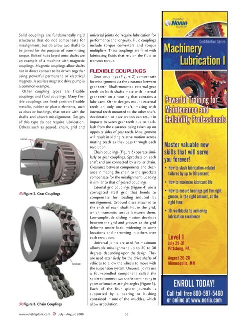
Figure 2. Gear Couplings<br />
Figure 3. Chain Couplings<br />
universal joints do require lubrication for<br />
performance and longevity. Fluid couplings<br />
include torque converters and torque<br />
multipliers. These couplings are filled with<br />
lubricating fluids that rely on the fluid to<br />
transmit torque.<br />
FLEXIBLE COUPLINGS<br />
Gear couplings (Figure 2) compensate<br />
for misalignment via the clearance between<br />
gear teeth. Shaft-mounted external gear<br />
teeth on both shafts mate with internal<br />
gear teeth on a housing that contains a<br />
lubricant. Other designs mount external<br />
teeth on only one shaft, mating with<br />
internal teeth mounted to the other shaft.<br />
Acceleration or deceleration can result in<br />
impacts between gear teeth due to backlash<br />
from the clearance being taken up on<br />
opposite sides of gear teeth. Misalignment<br />
will result in sliding relative motion across<br />
mating teeth as they pass through each<br />
revolution.<br />
Chain couplings (Figure 3) operate similarly<br />
to gear couplings. Sprockets on each<br />
shaft end are connected by a roller chain.<br />
Clearance between components and clearance<br />
in mating the chain to the sprockets<br />
compensate for the misalignment. Loading<br />
is similar to that of geared couplings.<br />
External grid couplings (Figure 4) use a<br />
corrugated steel grid that bends to<br />
compensate for loading induced by<br />
misalignment. Grooved discs attached to<br />
the ends of each shaft house the grid,<br />
which transmits torque between them.<br />
Low-amplitude sliding motion develops<br />
between the grid and grooves as the grid<br />
deforms under load, widening in some<br />
locations and narrowing in others over<br />
each revolution.<br />
Universal joints are used for maximum<br />
allowable misalignment up to 20 to 30<br />
degrees, depending upon the design. They<br />
are used extensively for the drive shafts of<br />
vehicles to allow the wheels to move with<br />
the suspension system. Universal joints use<br />
a four-spindled component called the<br />
spider to connect two shafts terminating in<br />
yokes or knuckles at right angles (Figure 5).<br />
Each of the four spider journals is<br />
supported by a bearing or bushing<br />
contained in one of the knuckles, which<br />
allow articulation.<br />
www.reliableplant.com <strong>July</strong> - <strong>August</strong> <strong>2008</strong> 33