Fortron PPS Product Brochure (B240) - Hi Polymers
Fortron PPS Product Brochure (B240) - Hi Polymers
Fortron PPS Product Brochure (B240) - Hi Polymers

You also want an ePaper? Increase the reach of your titles
YUMPU automatically turns print PDFs into web optimized ePapers that Google loves.
<strong>Fortron</strong> ®<br />
Polyphenylene sulphide (<strong>PPS</strong>)<br />
Venting the moulds<br />
All mould cavities must be effectively vented. An insufficiently<br />
vented mould can lead to burn marks on<br />
the moulded part caused by high compression of<br />
trapped air. Corrosive wear of the mould is also<br />
encouraged by unsatisfactory venting.<br />
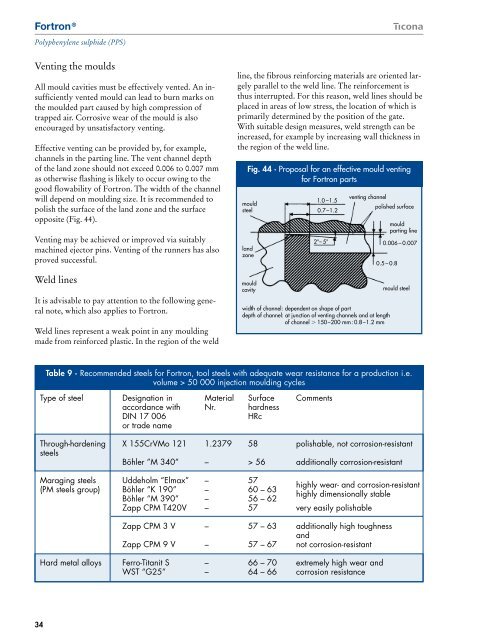
Effective venting can be provided by, for example,<br />
channels in the parting line. The vent channel depth<br />
of the land zone should not exceed 0.006 to 0.007 mm<br />
as otherwise flashing is likely to occur owing to the<br />
good flowability of <strong>Fortron</strong>. The width of the channel<br />
will depend on moulding size. It is recommended to<br />
polish the surface of the land zone and the surface<br />
opposite (Fig. 44).<br />
Venting may be achieved or improved via suitably<br />
machined ejector pins. Venting of the runners has also<br />
proved successful.<br />
Weld lines<br />
It is advisable to pay attention to the following general<br />
note, which also applies to <strong>Fortron</strong>.<br />
Weld lines represent a weak point in any moulding<br />
made from reinforced plastic. In the region of the weld<br />
line, the fibrous reinforcing materials are oriented largely<br />
parallel to the weld line. The reinforcement is<br />
thus interrupted. For this reason, weld lines should be<br />
placed in areas of low stress, the location of which is<br />
primarily determined by the position of the gate.<br />
With suitable design measures, weld strength can be<br />
increased, for example by increasing wall thickness in<br />
the region of the weld line.<br />
Fig. 44 · Proposal for an effective mould venting<br />
for <strong>Fortron</strong> parts<br />
mould<br />
steel<br />
land<br />
zone<br />
mould<br />
cavity<br />
1.0 –1.5<br />
0.7–1.2<br />
2°– 5°<br />
venting channel<br />
width of channel: dependent on shape of part<br />
depth of channel: at junction of venting channels and at length<br />
of channel 150–200 mm: 0.8–1.2 mm<br />
polished surface<br />
0.5 – 0.8<br />
mould<br />
parting line<br />
0.006 – 0.007<br />
mould steel<br />
Table 9 · Recommended steels for <strong>Fortron</strong>, tool steels with adequate wear resistance for a production i.e.<br />
volume > 50 000 injection moulding cycles<br />
Type of steel Designation in Material Surface Comments<br />
accordance with Nr. hardness<br />
DIN 17 006<br />
HRc<br />
or trade name<br />
Through-hardening X 155CrVMo 121 1.2379 58 polishable, not corrosion-resistant<br />
steels<br />
Böhler ”M 340” – > 56 additionally corrosion-resistant<br />
Maraging steels Uddeholm “Elmax” – 57<br />
highly wear- and corrosion-resistant<br />
(PM steels group) Böhler “K 190” – 60 – 63<br />
highly dimensionally stable<br />
Böhler “M 390” – 56 – 62<br />
Zapp CPM T420V – 57 very easily polishable<br />
Zapp CPM 3 V – 57 – 63 additionally high toughness<br />
and<br />
Zapp CPM 9 V – 57 – 67 not corrosion-resistant<br />
Hard metal alloys Ferro-Titanit S – 66 – 70 extremely high wear and<br />
WST “G25” – 64 – 66 corrosion resistance<br />
34