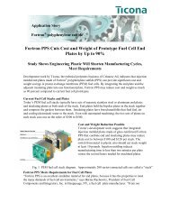
Fortron PPS Product Brochure (B240) - Hi Polymers
Fortron PPS Product Brochure (B240) - Hi Polymers
Fortron PPS Product Brochure (B240) - Hi Polymers

Create successful ePaper yourself
Turn your PDF publications into a flip-book with our unique Google optimized e-Paper software.
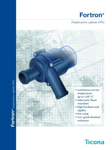
<strong>Fortron</strong> ®<br />
Polyphenylene sulphide (<strong>PPS</strong>)<br />
<strong>Fortron</strong> ® Polyphenylene sulphide (<strong>PPS</strong>)<br />
• continuous service<br />
temperature<br />
up to +240 °C<br />
• inherently flame<br />
retardant<br />
• high hardness and<br />
rigidity<br />
• low creep<br />
• very good chemical<br />
resistance
<strong>Fortron</strong> ®<br />
Polyphenylene sulphide (<strong>PPS</strong>)<br />
Contents<br />
1. Introduction 2<br />
2. Grades, supply forms, colour range,<br />
quality management 2<br />
2.1 <strong>Fortron</strong> grade range 3<br />
2.2 Colour masterbatches, coloration 4<br />
2.3 Quality management 4<br />
3. Properties 6<br />
3.1 Mechanical properties 6<br />
3.1.1 Properties under short-term stress 6<br />
3.1.2 Properties under long-term stress 7<br />
3.1.3 Fluctuating stress 15<br />
3.2 Thermal properties 17<br />
3.3 Electrical properties 21<br />
3.4 Surface properties 21<br />
3.4.1 Hardness 21<br />
3.4.2 Sliding and abrasion properties 21<br />
3.5 Specification listings 22<br />
3.5.1 MIL specifications 22<br />
3.5.2 Potable water regulations 22<br />
3.5.3 Automotive specifications 22<br />
4. Resistance to service environment<br />
effects 23<br />
4.1 Heat ageing 23<br />
4.2 Water absorption 23<br />
4.3 Chemical resistance 23<br />
4.4 UV resistance 29<br />
4.5 Flammability 29<br />
® = registered trademark
<strong>Fortron</strong> ®<br />
Polyphenylene sulphide (<strong>PPS</strong>)<br />
5. Processing, finishing 30<br />
5.1 Injection moulding 30<br />
5.1.1 Machine conditions 30<br />
5.1.2 Shrinkage 31<br />
5.1.3 Mould wall temperatures 33<br />
5.1.4 Mould design, design notes, sprue and gate 33<br />
5.1.5 Changing from another thermoplastic<br />
to <strong>Fortron</strong> 36<br />
5.1.6 Changing from <strong>Fortron</strong> to another<br />
thermoplastic 36<br />
5.1.7 Safety notes 37<br />
5.1.7.1 Thermal stress of the material 37<br />
5.1.7.2 Extraction at the processing machine 37<br />
5.1.7.3 Fire precautions 37<br />
5.2 Extrusion processing 37<br />
5.3 Annealing 37<br />
5.4 Machining 38<br />
5.4.1 General information on machining 38<br />
5.4.2 Tool recommendations for machining 39<br />
5.5 Assembly of <strong>Fortron</strong> mouldings 39<br />
5.5.1 Welding 39<br />
5.5.2 Snapfit joints 41<br />
5.5.3 Adhesive bonding 41<br />
5.5.4 Assembly with screws 41<br />
5.6 Laser marking 42<br />
5.7 Painting 42<br />
5.8 Printing 42<br />
5.9 Metallisation 42<br />
6. Use of recyclates 43<br />
7. UL cards 44<br />
8. Photo supplement showing typical<br />
applications 48<br />
9. Subject index 52<br />
10. Literature 54<br />
Introduction<br />
Grades, supply forms,<br />
colour range, quality management<br />
Properties<br />
Resistance to<br />
service environment effects<br />
Processing, finishing<br />
Use of recyclates<br />
UL cards<br />
Photo supplement<br />
showing typical applications<br />
1<br />
2<br />
3<br />
4<br />
5<br />
6<br />
7<br />
8<br />
Tables (selection):<br />
1 Physical properties<br />
3 Status of <strong>Fortron</strong> in UL tests<br />
4 CSA rating<br />
6 Resistance to chemicals<br />
Subject index<br />
9<br />
Literature<br />
10<br />
1
<strong>Fortron</strong> ®<br />
Polyphenylene sulphide (<strong>PPS</strong>)<br />
1. Introduction<br />
<strong>Fortron</strong> ® is a linear, partially crystalline polyphenylene<br />
sulphide. A phenylene ring and sulphur atom<br />
form the backbone of the macromolecule and give<br />
<strong>Fortron</strong> a number of unusual properties [1], [2]:<br />
– continuous service temperatures up to 240°C,<br />
short-term exposure up to 270°C,<br />
– inherently flame-retardant (UL 94: V-0, some<br />
grades 5 VA),<br />
– very good chemical and oxidation resistance,<br />
– high hardness and rigidity,<br />
– very low water absorption,<br />
– low creep, even at elevated temperatures.<br />
This combination of properties places <strong>Fortron</strong> in the<br />
category of a high-performance thermoplastic.<br />
<strong>Fortron</strong> is suitable for the manufacture of mouldings<br />
with good mechanical properties and thermal<br />
stability.<br />
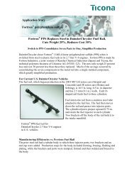
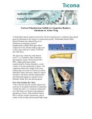
The most important applications for <strong>Fortron</strong> are in<br />
the electrical and electronics industries (e. g. plugs and<br />
multipoint connectors, bobbins, relays, switches,<br />
encapsulation of electronic components). <strong>Fortron</strong> is<br />
being employed increasingly in the automotive industry<br />
(air intake systems, pumps, valves, gaskets, components<br />
for exhaust gas recirculation systems).<br />
<strong>Fortron</strong> is also used to produce components for<br />
mechanical and precision engineering.<br />
2. Grades, supply forms,<br />
colour range,<br />
quality management<br />
<strong>Fortron</strong> is supplied in powder and pellet form. The<br />
current range of grades is described in section 2.1.<br />
By compounding <strong>Fortron</strong> with glass fibres and glass<br />
fibre/mineral filler blends, its rigidity, strength and<br />
heat resistance can be considerably increased.<br />
The <strong>Fortron</strong> range includes extrusion and injection<br />
moulding grades with different types and levels of<br />
additive and different melt viscosities. Specially<br />
easyflowing grades 1140L6, 4184L6, 6850L6 and<br />
6165A6 are available for thinwalled mouldings with<br />
unfavourable flow length/wall thickness ratios. Their<br />
properties are comparable with those of the corresponding<br />
grades with medium viscosity.<br />
The powder grades offer a variety of possibilities for<br />
use in powder technology, e. g. as heat-resistant<br />
binders or additives in PTFE compounds.<br />
The unreinforced pellet grades are used mainly for<br />
fibre manufacture (monofilaments and multifilaments)<br />
and for special applications in extrusion<br />
(e. g. pipes, semi-finished products, films). Section 2.1<br />
provides an overview.<br />
The range of grades is currently being expanded.<br />
Further details are available on request.<br />
For many components exposed to high service stresses,<br />
<strong>Fortron</strong> is the preferred alternative to light-metal<br />
alloys, thermosets and many other thermoplastics.<br />
® = registered trademark<br />
2
Polyphenylene sulphide (<strong>PPS</strong>)<br />
2.1 <strong>Fortron</strong> grade range<br />
Reinforced grades Fillers Description<br />
(pellets)<br />
1131L4 30% (w/w) glass fibres injection moulding grade, medium-range melt viscosity,<br />
permits flash-free production of complicated mouldings<br />
1140L4 40% (w/w) glass fibres injection moulding grade, medium-range melt viscosity<br />
with little tendency to form flash<br />
1140L6 40% (w/w) glass fibres injection moulding grade, like 1140L4 but with lower melt<br />
viscosity<br />
1140E7 40% (w/w) glass fibres improved injection moulding grade, low melt viscosity with<br />
little tendency to form flash<br />
4184L4 50% (w/w) injection moulding grade, comes between 1140L4 and<br />
glass fibres/mineral 6165A4 in terms of properties<br />
4184L6 50% (w/w) injection moulding grade, like 4184L4 but with lower melt<br />
glass fibres/mineral viscosity<br />
4665B6 65% (w/w) injection moulding grade, like 6165A4/A6 but with better<br />
glass fibres/mineral tracking resistance and very low warpage<br />
6160B4 60% (w/w) injection moulding grade, lower density, low corrosion,<br />
glass fibres/mineral specially suitable for electronic components<br />
6165A4 65 % (w/w) injection moulding grade, medium-range melt viscosity, lower<br />
glass fibres/mineral shrinkage and warpage than glass-fibre-reinforced grades<br />
6165A6 65% (w/w) injection moulding grade, like 6165A4 but with lower melt<br />
glass fibres/mineral viscosity<br />
6850L6 50% (w/w) injection moulding grade, low melt viscosity, very low<br />
glass fibres/mineral warpage<br />
1140L0 40% (w/w) glass fibres extrusion grade<br />
<strong>Fortron</strong> ® 3<br />
1<br />
2<br />
Unreinforced grades Supply form Description<br />
(powder and pellets)<br />
0203B6 coarse powder (average very low melt viscosity<br />
particle size 300 µm),<br />
good free-flowing properties<br />
0203P6 pellets very low melt viscosity (can be supplied on request)<br />
0205B4 coarse powder (average low melt viscosity<br />
particle size 300 µm),<br />
good free-flowing properties<br />
0205B4/20µm finely ground powder for powder technology, e. g. as heat-resistant binder,<br />
(average particle size as additive in PTFE compounds<br />
≈ 20 µm)<br />
0205P4 pellets low melt viscosity<br />
0214B1 coarse powder (average medium-range melt viscosity<br />
particle size 300 µm),<br />
good free-flowing properties<br />
0214C1 pellets medium-range melt viscosity<br />
0320B0 coarse powder (average high melt viscosity<br />
particle size 300 µm),<br />
good free-flowing properties<br />
0320C0 pellets high melt viscosity
<strong>Fortron</strong> ®<br />
Polyphenylene sulphide (<strong>PPS</strong>)<br />
2.2 Colour masterbatches, coloration<br />
The reinforced grades are supplied in natural, black<br />
and brown colours and the unreinforced grades in<br />
natural colour.<br />
In-house coloration of <strong>Fortron</strong> is possible and serves<br />
to identify and distinguish components.<br />
For this purpose, a range of <strong>Fortron</strong> colour masterbatches<br />
with a high pigment content is available.<br />
Colour masterbatches are supplied as granules and are<br />
used to colour natural <strong>Fortron</strong> grades. The recommended<br />
concentrations are 40 : 1 for black and<br />
brown, 20 : 1 for the other colours.<br />
If processors wish to use their own colorants, only<br />
pigments which can resist the processing temperatures<br />
of <strong>Fortron</strong> (up to 350°C) without decomposition or<br />
colour change may be employed. The pigment content<br />
should not exceed 1.5% (w/w). <strong>Hi</strong>gher pigment<br />
contents may cause a reduction in mechanical properties<br />
and flowability.<br />
The following colour masterbatches are currently<br />
available:<br />
2.3 Quality management<br />
Within the Ticona Group in Europe the <strong>Fortron</strong><br />
<strong>Product</strong> Team has obtained registration acc. to ISO<br />
9001 and QS-9000 (DOS [German Association for<br />
the Certification of Quality Systems], reg. no. 2719).<br />
This indicates that the quality system meets the<br />
requirements of this international standard. The use<br />
of SPC methods to monitor product quality is part of<br />
this quality system (see also the brochures “Quality<br />
Assurance Polymer Material” and “Statistical Process<br />
Control”).<br />
By regular self-assessment in accordance with the<br />
automotive requirements of QS-9000 we are constantly<br />
developing our quality system to meet the<br />
needs of our customers.<br />
To foster effective partnerships with our customers<br />
we offer to conclude quality agreements and also to<br />
issue test certificates. These agreements document the<br />
specifications for our products. In addition, we can<br />
agree to issue an inspection certificate in accordance<br />
with EN 10 204-3.1B. This contains measured values<br />
relating to the batch of which the delivery is part.<br />
SD3002 K40 black SJ3013 K20 green<br />
SY3004 K40 brown SN3012 K20 orange<br />
SC3010 K20 dark grey SL3017 K20 yellow<br />
SC3011 K20 pale grey SS3006 K20 red<br />
SG3005 K20 blue<br />
All colour masterbatches are cadmium-free.<br />
Mechanical properties such as tensile strength and<br />
elongation at break may be slightly altered by the<br />
addition of colorants.<br />
It should be noted that formulations cannot be expected<br />
to give a permanently true colour match. This<br />
is because photooxidative reactions taking place under<br />
light and heat lead to colour changes in very thin edge<br />
layers of components. No change in mechanical properties<br />
has been detected in such cases.<br />
4
<strong>Fortron</strong> ®<br />
Polyphenylene sulphide (<strong>PPS</strong>)<br />
5<br />
2
<strong>Fortron</strong> ®<br />
Polyphenylene sulphide (<strong>PPS</strong>)<br />
3. Properties<br />
This section discusses the important characteristic<br />
properties of <strong>Fortron</strong>. They have been determined<br />
largely by standard test methods.<br />
The physical property values of <strong>Fortron</strong> are given in<br />
table 1 on pages 8 and 9. This table is also available as<br />
a pull-out leaflet (B 260 FB E).<br />
Descriptions of the <strong>Fortron</strong> grades and their properties<br />
are available on the ® CAMPUS 4.1 data base diskette.<br />
This diskette can be used on IBM-compatible<br />
PCs; the diskette can be ordered by telephoning<br />
(++ 49-69) 305 70 63.<br />
The property values determined on test specimens by<br />
standard test methods are guide values and can be<br />
used as a basis for comparing different materials.<br />
However they have only limited applicability to<br />
finished parts. The strength of a component depends<br />
to a great extent on its design and hence design<br />
strength is the criterion used to assess loadbearing<br />
capacity.<br />
3.1 Mechanical properties<br />
To characterize the dependence of the mechanical<br />
properties of a plastic on temperature, the shear<br />
modulus G and the mechanical loss factor d are used,<br />
fig. 1.<br />
Shear modulus G<br />
Fig. 1 · Shear modulus G and loss factor d<br />
of some <strong>Fortron</strong> grades as function of<br />
temperature, measured in the torsion<br />
pendulum test according to ISO 6721-1,2<br />
10 3<br />
10 4<br />
10 –1 10 –2<br />
MPa<br />
a<br />
G<br />
10 3<br />
b<br />
10 2<br />
10 2<br />
c<br />
10 1<br />
c<br />
10 1<br />
10 0<br />
d<br />
10 0<br />
10 –1<br />
b<br />
a<br />
–100 –60 –20 20 60 100 140 180 220 °C 300<br />
Temperature<br />
a <strong>Fortron</strong> 6165A4<br />
b <strong>Fortron</strong> 1140L4<br />
c <strong>Fortron</strong> 0214C1<br />
Mechanical loss factor d<br />
3.1.1 Properties under short-term stress<br />
The behaviour of materials under dynamic short-term<br />
stress can be examined in the tensile test according to<br />
ISO 527-1, 2. This test enables important properties<br />
as tensile strength and strain at break to be determined.<br />
Figs. 2 and 3 show the stress-strain properties of<br />
<strong>Fortron</strong> 1140L4 and 6165A4 at different temperatures.<br />
In the upper temperature range (150, 200°C), the<br />
values for strain at break are relatively high; this is<br />
most marked with the 40% glass-reinforced grade<br />
<strong>Fortron</strong> 1140L4.<br />
Tensile strength<br />
Tensile strength<br />
Fig. 2 · Stress/strain curves for <strong>Fortron</strong> 1140L4,<br />
measured at different temperatures<br />
200<br />
MPa<br />
150<br />
–40°C<br />
23°C<br />
100<br />
75°C<br />
150°C<br />
50<br />
200°C<br />
0<br />
0 1 2 3 %<br />
Tensile strain at break<br />
Fig. 3 · Stress/strain curves for <strong>Fortron</strong> 6165A4,<br />
measured at different temperatures<br />
200<br />
MPa<br />
150<br />
100<br />
50<br />
–40°C<br />
75°C<br />
23°C<br />
150°C<br />
0<br />
200°C<br />
0 0.5 1.0 1.5 % 2.0<br />
Tensile strain at break<br />
Other properties measured under short-term stress<br />
are the different elastic moduli, i. e. the tensile modulus<br />
and flexural modulus, determined according to<br />
IO 527-1, 2 and ISO 178. The values provide an indication<br />
of rigidity and are used not only to characterize<br />
plastics but also for strength calculation and the<br />
design of moulded parts.<br />
®<br />
CAMPUS = registered trademark of CWFG,<br />
Frankfurt am Main, Germany<br />
6
<strong>Fortron</strong> ®<br />
Polyphenylene sulphide (<strong>PPS</strong>)<br />
The high tensile and flexural moduli of the reinforced<br />
<strong>Fortron</strong> grades should be noted, see figs. 4 and 5.<br />
In these two properties, <strong>Fortron</strong> 6165A4, containing<br />
65% filler blend, is superior to the grades with 40%<br />
glass fibres.<br />
Tensile modulus<br />
Flexural modulus<br />
Fig. 4 · Tensile modulus of the most important<br />
<strong>Fortron</strong> Grades as a function of temperature,<br />
measured according to ISO 527-1,2<br />
20 000<br />
MPa<br />
15 000<br />
10 000<br />
5 000<br />
a<br />
b<br />
c<br />
0<br />
–40 0 40 80 120 160 200 °C 240<br />
a <strong>Fortron</strong> 6165A4<br />
b <strong>Fortron</strong> 4184L4<br />
c <strong>Fortron</strong> 1140L4<br />
Temperature<br />
Fig. 5 · Flexural modulus of the most important<br />
<strong>Fortron</strong> grades as a function of temperature,<br />
measured according to ISO 178<br />
20 000<br />
MPa<br />
15 000<br />
10 000<br />
5 000<br />
a<br />
b<br />
c<br />
0<br />
–40 0 40 80 120 160 200 °C 240<br />
a <strong>Fortron</strong> 6165A4<br />
b <strong>Fortron</strong> 4184L4<br />
c <strong>Fortron</strong> 1140L4<br />
Temperature<br />
3.1.2 Properties under long-term stress<br />
The results of long-term tests carried out under<br />
various conditions provide the design engineer with a<br />
basis for calculation when designing components subjected<br />
to prolonged stress.<br />
The properties of plastics under long-term tensile<br />
stress are tested by two basic methods:<br />
– creep rupture test according to ISO 899-1 (deformation<br />
increase in specimen held under constant<br />
stress),<br />
– stress relaxation test according to DIN 53 441<br />
(stress decay in specimen held under constant<br />
strain).<br />
The first test gives the creep strength, i. e. the time to<br />
rupture of a test bar loaded with a specified stress<br />
under defined environmental conditions. These tests<br />
are carried out on tensile test bars (uniaxial stress condition)<br />
in air or another medium.<br />
The strain values and creep moduli determined in the<br />
creep rupture test under tensile stress also serve as a<br />
good approximation for the values to be expected<br />
under flexural and compressive stress.<br />
The deformation of a plastic component is not only<br />
time- and temperature-dependent but is also a function<br />
of the type of stress. Strictly speaking, separate characteristic<br />
values should be determined for each type<br />
of stress. However, for relatively small deformation,<br />
the variation between the characteristic values is<br />
negligible so that, for example, the time-dependent<br />
compression of a component under compressive<br />
stress may be calculated with sufficient accuracy using<br />
the flexural creep modulus (determined under flexural<br />
stress).<br />
The results of creep tests under uniaxial stress have<br />
only limited applicability to the multiaxial stress condition.<br />
Creep tests under constant stress show the behaviour<br />
of a material under constant load; the initial strain<br />
caused by the applied stress increases with time, i. e.<br />
material “creeps”.<br />
This property of thermoplastic materials is exhibited<br />
only to a very limited extent in the case of the<br />
reinforced <strong>Fortron</strong> grades. This can be seen in the<br />
following figs. 6 – 13, which show important characteristic<br />
functions for the creep behaviour of <strong>Fortron</strong><br />
1140L4 and 6165A4 under tensile stress and at temperatures<br />
of 23, 120, 150 and 200°C. The required tensile<br />
creep tests were carried out up to a time under<br />
load of 10 3 h and extrapolated to 10 4 h.<br />
3<br />
7
<strong>Fortron</strong> ®<br />
Polyphenylene sulphide (<strong>PPS</strong>)<br />
Table 1 · Physical properties of <strong>Fortron</strong> (<strong>PPS</strong>)<br />
Property Unit Test method<br />
Reinforcement level (rounded-off) % (w/w) –<br />
Density g/cm 3 ISO 1183<br />
Water absorption (24 h immersion at 23°C) % ASTM D 570<br />
Moulding shrinkage (p c = 500 bar, h = 2 mm) % ISO 294-4<br />
(Typical values) 1 ) (p c = 500 bar, h = 4 mm) % ISO 294-4<br />
Mechanical properties, measured at 23°C, 50% relative humidity<br />
Tensile strength 2 ) MPa ISO 527 parts 1 and 2<br />
Strain at break 2 ) % ISO 527 parts 1 and 2<br />
Tensile modulus MPa ISO 527 parts 1 and 2<br />
Flexural strength MPa ISO 178<br />
Flexural modulus MPa ISO 178<br />
Compressive strength MPa ISO 604<br />
Compressive modulus MPa ISO 604<br />
Impact strength (Charpy) kJ/m 2 ISO 179/1eU<br />
Notched impact strength (Charpy) kJ/m 2 ISO 179/1eA<br />
Notched impact strength (Izod) kJ/m 2 ISO 180/1A<br />
Ball indentation hardness, 30 sec. value N/mm 2 ISO 2039 part 1<br />
Rockwell hardness, scale M – ASTM D 785<br />
Thermal properties<br />
Heat deflection HDT/A at 1.8 MPa °C<br />
temperature HDT/C at 8.0 MPa °C<br />
ISO 75 parts 1 and 2<br />
Coefficient of linear (between –50 and 90°C) °C –1 ISO 11359-2<br />
thermal expansion 1 ) (between 90 and 250°C) °C –1 ISO 11359-2<br />
Electrical properties, measured at 23°C, 50% relative humidity<br />
Relative permittivity ε r at 10 kHz –<br />
at 1 MHz –<br />
Dissipation factor tan δ at 10 kHz –<br />
IEC 60250<br />
at 1 MHz –<br />
Electric strength kV/mm IEC 60243 part 1 3 )<br />
Comparative tracking index CTI<br />
Volume resistivity<br />
–<br />
Ω · m<br />
CTI M<br />
Surface resistivity<br />
–<br />
Ω<br />
IEC 60112<br />
IEC 60093 4 )<br />
Ball indentation test °C IEC 60089 (Sec) 82 March 1993<br />
Fire behaviour<br />
Flammability Class UL 94<br />
Hot wire test (at 1, 2 and 4 mm wall thickness) °C IEC 60695 part 1 and 2<br />
1<br />
) Values from longitudinal transverse directions 4<br />
) Measured with sticking electrodes (The data quoted are typical values)<br />
2<br />
) Testing speed 5 mm/min 5<br />
) Only for 4665B6 black<br />
3<br />
) P 25/P 75 in transformer oil according<br />
to IEC 60296, 1 mm thick sheet<br />
p c = cavity pressure<br />
8
Polyphenylene sulphide (<strong>PPS</strong>)<br />
pellets reinforced unreinforced powder extrusion<br />
with glass fibres pellet grades grades grades<br />
1131L4 1140L4*) 1140E7 **) ***) 1140L0<br />
30 40 40 – – 40<br />
1.56 1.65 1.65 1.35 1.35 1.65<br />
0.02 0.02 0.02 0.01 0.01 –<br />
0.3/0.7 0.2/0.6 0.2/0.6 1.2/1.5 – –<br />
0.5/0.8 0.4/0.6 0.4/0.6 1.5/1.8 – –<br />
®<br />
165 195 150 75 75 185<br />
1.9 1.9 1.2 – – 1.9<br />
12 200 14 700 15 700 3 700 3 700 –<br />
255 285 230 130 130 280<br />
12 000 14 500 – 3 800 3 800 14 000<br />
– 265 – – – –<br />
– 15 000 – – – –<br />
42 53 28 – – –<br />
8 10 7 – – 10<br />
8 10 7 – – –<br />
– 322 – 190 – –<br />
– 100 100 93 – –<br />
<strong>Fortron</strong><br />
9<br />
3<br />
265 270 270 110 110 –<br />
205 215 215 – – 202<br />
– 26·10 –6 – – – –<br />
– 48·10 –6 – – – –<br />
– 4.0 – – – –<br />
– 4.1 – – – –<br />
– 0.2 · 10 –3 – – – –<br />
– 2.0 · 10 –3 – – – –<br />
– 28 – – – –<br />
– 125 – 100 – –<br />
– 100 – – – –<br />
> 10 13 > 10 13 – – – –<br />
> 10 15 > 10 15 > 10 15 > 10 15 > 10 15 –<br />
– 260 – – – –<br />
V-0 V-0 V-0 – – –<br />
(0.38 mm) (0.38 mm) (0.85 mm) – – –<br />
960 960 – – – –<br />
*) The properties of 1140L6 are comparable to those of 1140L4 ***) The properties were determined on injection moulded<br />
**) The properties apply to all unreinforced pellet grades ***) specimens and apply to all powder grades
<strong>Fortron</strong> ®<br />
Polyphenylene sulphide (<strong>PPS</strong>)<br />
Table 1 · Physical properties of <strong>Fortron</strong> (<strong>PPS</strong>)<br />
Property Unit Test method<br />
Reinforcement level (rounded-off) % (w/w) –<br />
Density g/cm 3 ISO 1183<br />
Water absorption (24 h immersion at 23°C) % ASTM D 570<br />
Moulding shrinkage (p c = 500 bar, h = 2 mm) % ISO 294-4<br />
(Typical values) 1 ) (p c = 500 bar, h = 4 mm) % ISO 294-4<br />
Mechanical properties, measured at 23°C, 50% relative humidity<br />
Tensile strength 2 ) MPa ISO 527 parts 1 and 2<br />
Strain at break 2 ) % ISO 527 parts 1 and 2<br />
Tensile modulus MPa ISO 527 parts 1 and 2<br />
Flexural strength MPa ISO 178<br />
Flexural modulus MPa ISO 178<br />
Compressive strength MPa ISO 604<br />
Compressive modulus MPa ISO 604<br />
Impact strength (Charpy) kJ/m 2 ISO 179/1eU<br />
Notched impact strength (Charpy) kJ/m 2 ISO 179/1eA<br />
Notched impact strength (Izod) kJ/m 2 ISO 180/1A<br />
Ball indentation hardness, 30 sec. value N/mm 2 ISO 2039 part 1<br />
Rockwell hardness, scale M – ASTM D 785<br />
Thermal properties<br />
Heat deflection HDT/A at 1.8 MPa °C<br />
temperature HDT/C at 8.0 MPa °C<br />
ISO 75 parts 1 and 2<br />
Coefficient of linear (between –50 and 90°C) °C –1 ISO 11359-2<br />
thermal expansion 1 ) (between 90 and 250°C) °C –1 ISO 11359-2<br />
Electrical properties, measured at 23°C, 50% relative humidity<br />
Relative permittivity ε r at 10 kHz –<br />
at 1 MHz –<br />
Dissipation factor tan δ at 10 kHz –<br />
IEC 60250<br />
at 1 MHz –<br />
Electric strength kV/mm IEC 60243 part 1 3 )<br />
Comparative tracking index CTI<br />
Volume resistivity<br />
–<br />
Ω · m<br />
CTI M<br />
Surface resistivity<br />
–<br />
Ω<br />
IEC 60112<br />
IEC 60093 4 )<br />
Ball indentation test °C IEC 60089 (Sec) 82 March 1993<br />
Fire behaviour<br />
Flammability Class UL 94<br />
Hot wire test (at 1, 2 and 4 mm wall thickness) °C IEC 60695 part 1 and 2<br />
1<br />
) Values from longitudinal transverse directions 4<br />
) Measured with sticking electrodes (The data quoted are typical values)<br />
2<br />
) Testing speed 5 mm/min 5<br />
) Only for 4665B6 black<br />
3<br />
) P 25/P 75 in transformer oil according<br />
to IEC 60296, 1 mm thick sheet<br />
p c = cavity pressure<br />
10
Polyphenylene sulphide (<strong>PPS</strong>)<br />
pellets reinforced with glass fibres and mineral filler<br />
4184L4*) 4665B6 6160B4 6165A4**) 6850L6<br />
50 65 60 65 50<br />
1.80 2.03 1.90 1.95 1.80<br />
0.02 0.02 0.02 0.02 0.02<br />
0.3/0.6 0.2/0.6 0.2/0.6 0.2/0.6 0.3/0.6<br />
0.4/0.7 0.3/0.7 0.3/0.7 0.3/0.7 0.4/0.7<br />
®<br />
165 110 145 130 125<br />
1.4 1.2 1.0 1.2 1.0<br />
16 600 17 300 17 300 19 000 18 500<br />
250 180 220 210 190<br />
16 200 16 000 16 700 18 800 16 800<br />
245 200 220 230 230<br />
16 200 – – 18 500 –<br />
29 18 27 20 16<br />
7 6 7 7 4<br />
7 5 6 6 4<br />
365 459 403 428 –<br />
– – – 100 –<br />
<strong>Fortron</strong><br />
11<br />
3<br />
270 270 270 270 270<br />
215 215 220 215 215<br />
24 · 10 –6 – – 19 · 10 –6 23 · 10 –6<br />
46 · 10 –6 – – 36 · 10 –6 46 · 10 –6<br />
4.7 – – 5.4 –<br />
4.7 5.3 4.9 5.6 –<br />
0.8 · 10 –3 – – 1.0 · 10 –3 1.0 · 10 –3<br />
2.0 · 10 –3 2.0 · 10 –3 1.0 · 10 –3 2.0 · 10 –3 1.0 · 10 –3<br />
27 25 – 25 25<br />
150 250 5 ) 175 175 –<br />
150 – – 200 –<br />
> 10 13 > 10 13 > 10 13 > 10 13 –<br />
> 10 15 > 10 15 > 10 15 > 10 15 > 10 15<br />
– 260 260 275 –<br />
V-0 V-0 V-0 V-0 V-0<br />
(0.75 mm) (0.45 mm) (0.81 mm) (0.75 mm) (0.38 mm)<br />
960 960 960 960 –<br />
*) The properties of 4184L6 are comparable to those of 4184L4<br />
**) The properties of 6165A6 are comparable to those of 6165A4
<strong>Fortron</strong> ®<br />
Polyphenylene sulphide (<strong>PPS</strong>)<br />
Fig. 6 · Characteristic values for the creep<br />
behaviour of <strong>Fortron</strong> 1140L4 under tensile stress<br />
(standard climatic conditions 23/50)<br />
Fig. 7 · Characteristic values for the creep<br />
behaviour of <strong>Fortron</strong> 6165A4 under tensile stress<br />
(standard climatic conditions 23/50)<br />
90<br />
MPa<br />
60<br />
10 –1 – 10 4 h<br />
60<br />
MPa<br />
40<br />
10 –1 h<br />
10 4 h<br />
10 3 h<br />
10 2 h<br />
10 1 h<br />
10 0 h<br />
Stress <br />
Stress <br />
30<br />
20<br />
0<br />
0<br />
0 0.2 0.4 0.6 % 0.8<br />
0 0.2 0.4 0.6 % 0.8<br />
Strain <br />
Strain <br />
Strain <br />
3.0<br />
%<br />
1.0<br />
0.3<br />
= 80 MPa<br />
70 MPa<br />
60 MPa<br />
50 MPa<br />
40 MPa<br />
30 MPa<br />
Strain <br />
1.00<br />
%<br />
0.30<br />
0.10<br />
= 60 MPa<br />
50 MPa<br />
40 MPa<br />
30 MPa<br />
20 MPa<br />
10 MPa<br />
0.1<br />
0.03<br />
10 –1 10 0 10 1 10 2 10 3 h 10 4<br />
10 –1 10 0 10 1 10 2 10 3 h 10 4<br />
Time under stress<br />
Time under stress<br />
25 000<br />
25 000<br />
Tensile creep modulus<br />
MPa<br />
20 000<br />
15 000<br />
= 20 MPa<br />
40 MPa<br />
60 MPa<br />
80 MPa<br />
Tensile creep modulus<br />
MPa<br />
20 000<br />
15 000<br />
= 20 MPa<br />
40 MPa<br />
60 MPa<br />
10 000<br />
10 –1 10 0 10 1 10 2 10 3 h 10 4<br />
Time under stress<br />
10 000<br />
10 –1 10 0 10 1 10 2 10 3 h 10 4<br />
Time under stress<br />
12
Polyphenylene sulphide (<strong>PPS</strong>)<br />
Fig. 8 · Characteristic values for the creep<br />
behaviour of <strong>Fortron</strong> 1140L4 under tensile stress<br />
at a temperature of 120°C<br />
3<br />
<strong>Fortron</strong> ® 13<br />
Fig. 9 · Characteristic values for the creep<br />
behaviour of <strong>Fortron</strong> 6165A4 under tensile stress<br />
at a temperature of 120°C<br />
30<br />
MPa<br />
20<br />
10 0 h<br />
10 –1 h<br />
10 1 h<br />
10 2 h<br />
10 3 h<br />
10 4 h<br />
30<br />
MPa<br />
20<br />
10 –1 h<br />
10 0 h<br />
10 1 h<br />
10 2 h<br />
10 3 h<br />
10 4 h<br />
Stress <br />
Stress <br />
10<br />
10<br />
0<br />
0 0.4 0.8 1.2 % 1.6<br />
Strain <br />
0<br />
0 0.3 0.6 0.9 % 1.2<br />
Strain <br />
Strain <br />
3.00<br />
%<br />
1.00<br />
0.30<br />
0.10<br />
= 30 MPa<br />
10 MPa<br />
5 MPa<br />
25 MPa<br />
20 MPa<br />
15 MPa<br />
Strain <br />
1.00<br />
%<br />
0.30<br />
0.10<br />
= 30 MPa<br />
25 MPa<br />
20 MPa<br />
15 MPa<br />
10 MPa<br />
5 MPa<br />
0.03<br />
0.03<br />
10 –1 10 0 10 1 10 2 10 3 h 10 4<br />
Time under stress<br />
10 –1 10 0 10 1 10 2 10 3 h 10 4<br />
Time under stress<br />
8 000<br />
12 000<br />
Tensile creep modulus<br />
MPa<br />
6 000<br />
4 000<br />
= 5 MPa<br />
20 MPa<br />
30 MPa<br />
Tensile creep modulus<br />
MPa<br />
8 000<br />
4 000<br />
= 5 MPa<br />
10 MPa<br />
20 MPa<br />
30 MPa<br />
2 000<br />
10 –1 10 0 10 1 10 2 10 3 h 10 4<br />
Time under stress<br />
0<br />
10 –1 10 0 10 1 10 2 10 3 h 10 4<br />
Time under stress
<strong>Fortron</strong> ®<br />
Polyphenylene sulphide (<strong>PPS</strong>)<br />
Fig. 10 · Characteristic values for the creep<br />
behaviour of <strong>Fortron</strong> 1140L4 under tensile stress<br />
at a temperature of 150°C<br />
Fig. 11 · Characteristic values for the creep<br />
behaviour of <strong>Fortron</strong> 6165L4 under tensile stress<br />
at a temperature of 150°C<br />
Stress <br />
25<br />
MPa<br />
20<br />
15<br />
10<br />
10 –1 h<br />
10 0 h<br />
10 1 h<br />
10 2 h<br />
10 3 h<br />
Stress <br />
20<br />
MPa<br />
15<br />
10<br />
10 –1 h<br />
10 0 h<br />
10 1 h<br />
10 2 h<br />
10 3 h<br />
5<br />
5<br />
0<br />
0<br />
0 0.5 1.0 % 1.5<br />
0 0.2 0.4 0.6 0.8 % 1.0<br />
Strain <br />
Strain <br />
Strain <br />
3.00<br />
%<br />
1.00<br />
0.30<br />
0.10<br />
0.03<br />
17.5 MPa<br />
15 MPa<br />
10 MPa<br />
20 MPa<br />
5 MPa<br />
= 22.5 MPa<br />
Strain <br />
3.0<br />
%<br />
1.0<br />
0.3<br />
0.1<br />
= 17.5 MPa<br />
15 MPa<br />
12.5 MPa<br />
10 MPa<br />
7.5 MPa<br />
5 MPa<br />
10 –1 10 0 10 1 10 2 10 3 h 10 4<br />
10 –1 10 0 10 1 10 2 10 3 h 10 4<br />
Time under stress<br />
Time under stress<br />
Tensile creep modulus<br />
10 000<br />
MPa<br />
8 000<br />
6 000<br />
4 000<br />
2 000<br />
= 2.5 to 22.5 MPa<br />
Tensile creep modulus<br />
6 000<br />
MPa<br />
4 000<br />
2 000<br />
= 2.5 to 17.5 MPa<br />
0<br />
10 0 10 1 10 2 10 3 h 10 4<br />
Time under stress<br />
0<br />
10 0 10 1 10 2 10 3 h 10 4<br />
Time under stress<br />
14
<strong>Fortron</strong> ®<br />
Polyphenylene sulphide (<strong>PPS</strong>)<br />
Fig. 12 · Characteristic values for the creep<br />
behaviour of <strong>Fortron</strong> 1140L4 under tensile stress<br />
at a temperature of 200°C<br />
Fig. 13 · Characteristic values for the creep<br />
behaviour of <strong>Fortron</strong> 6165A4 under tensile stress<br />
at a temperature of 200°C<br />
20<br />
MPa<br />
15<br />
10 –1 h<br />
10 0 h<br />
10 1 h<br />
10 2 h<br />
10 3 h<br />
10 4 h<br />
15<br />
MPa<br />
10<br />
10 –1 h<br />
10 0 h<br />
10 1 h<br />
10 2 h<br />
10 3 h<br />
10 4 h<br />
Stress <br />
10<br />
Stress <br />
5<br />
5<br />
0<br />
0 0.4 0.8 1.2 % 1.6<br />
Strain <br />
0<br />
0 0.3 0.6 0.9 % 1.2<br />
Strain <br />
3<br />
Strain <br />
3.0<br />
%<br />
1.0<br />
0.3<br />
= 17.5 MPa<br />
15 MPa<br />
7.5 MPa<br />
5 MPa<br />
12.5 MPa<br />
10 MPa<br />
Strain <br />
3.00<br />
%<br />
1.00<br />
0.30<br />
0.10<br />
= 15 MPa<br />
7.5 MPa<br />
5 MPa<br />
2.5 MPa<br />
12.5 MPa<br />
10 MPa<br />
0.1<br />
10 –1 10 0 10 1 10 2 10 3 h 10 4<br />
Time under stress<br />
6 000<br />
0.03<br />
10 –1 10 0 10 1 10 2 10 3 h 10 4<br />
Time under stress<br />
6 000<br />
Tensile creep modulus<br />
MPa<br />
4 000<br />
2 000<br />
= 5 to 17.5 MPa<br />
Tensile creep modulus<br />
MPa<br />
4 000<br />
2 000<br />
= 2.5 MPa 5 MPa<br />
10 MPa<br />
15 MPa<br />
0<br />
10 –1 10 0 10 1 10 2 10 3 h 10 4<br />
Time under stress<br />
0<br />
10 –1 10 0 10 1 10 2 10 3 h 10 4<br />
Time under stress<br />
Besides the creep tests under tensile stress described<br />
above, behaviour under flexural stress is important in<br />
designing many structural components. Figs. 14 and<br />
15 show the flexural creep modulus curves for<br />
<strong>Fortron</strong> 1140L4 and 6165A4 at 80, 120 and 200°C.<br />
3.1.3 Fluctuating stress<br />
Design parts subject to periodic loading must be<br />
designed on the basis of the fatigue strength. This is<br />
defined as the stress amplitude σ a determined in the<br />
fatigue test – with a specified average stress σ m – that a<br />
specimen withstands without failure for a specific<br />
number of load cycles, for example 10 7 (“Wöhler<br />
curve”). The various stress ranges in which such tests<br />
are carried out are shown in fig. 16.<br />
15
<strong>Fortron</strong> ®<br />
Polyphenylene sulphide (<strong>PPS</strong>)<br />
For <strong>Fortron</strong> the fatigue strength at 10 7 load cycles is<br />
about 15 to 30% of the tensile strength determined in<br />
the tensile test. For fairly brittle products with high<br />
strength and low elongation the tensile strength is<br />
identical to the tensile stress at break.<br />
Fig. 17 shows the behaviour of <strong>Fortron</strong> 1140L4 and<br />
6165A4 in the fluctuating tensile stress range at 23°C;<br />
fig. 18 shows the same at 90°C.<br />
Fig. 14 · Flexural creep modulus of <strong>Fortron</strong><br />
1140L4 and 6165A4 at 80 and 120°C (measured<br />
with an outer-fibre stress b = 50 MPa)<br />
20 000<br />
MPa<br />
15 000<br />
1140L4<br />
6165A4<br />
The fatigue strength falls with increasing temperature<br />
(fig. 18) and load cycle frequency as well as with the<br />
existence of stress peaks in notched components.<br />
The Wöhler curves for fluctuating flexural stress for<br />
four <strong>Fortron</strong> grades are shown in fig. 19.<br />
+ <br />
– <br />
Fig. 16 · Stress ranges in fatigue tests<br />
m a<br />
m a<br />
u 0<br />
m a<br />
m 0<br />
m <br />
compression<br />
– + tension<br />
a<br />
m a<br />
u 0<br />
m a m a m a<br />
m a<br />
time<br />
Flexural creep modulus<br />
10 000<br />
5 000<br />
range for fluctuating<br />
stresses<br />
(under compression)<br />
range for alternating<br />
stresses<br />
range for fluctuating<br />
stresses<br />
(under tension)<br />
Fig. 17 · Wöhler curve for <strong>Fortron</strong> 1140L4 and<br />
6165A4, determined in the fluctuating tensile<br />
stress range at 23°C<br />
Flexural creep modulus<br />
Fig. 15 · Flexural creep modulus of <strong>Fortron</strong><br />
1140L4 and 6165A4 at 200°C (measured<br />
with an outer-fibre stress b = 30 MPa)<br />
6 000<br />
MPa<br />
5 000<br />
4 000<br />
3 000<br />
2 000<br />
1000<br />
0<br />
10 –2 10 –1 10 0 10 1 10 2 10 3 h 10 4<br />
Time under stress<br />
0<br />
10 –2 10 –1 10 0 10 1 10 2 10 3 h 10 4<br />
Time under stress<br />
1140L4<br />
6165A4<br />
Fatigue strength under<br />
fluctuating tensile stress<br />
Fatigue strength under<br />
fluctuating tensile stress<br />
60<br />
MPa<br />
50<br />
40<br />
30<br />
20<br />
10<br />
0<br />
time<br />
0<br />
10 2 10 3 10 4 10 5 10 6 10 7 10 8<br />
Fig. 18 · Wöhler curve for <strong>Fortron</strong> 1140L4 and<br />
6165A4, determined in the fluctuating tensile<br />
stress range at 90°C<br />
40<br />
MPa<br />
30<br />
20<br />
10<br />
m = a<br />
1040L4<br />
6165B4<br />
m = a<br />
6165B4<br />
1040L4<br />
Stress cycles N<br />
0<br />
time<br />
0<br />
10 2 10 3 10 4 10 5 10 6 10 7 10 8<br />
Stress cycles N<br />
Test temperature 23°C<br />
Stress cycle frequency 5 Hz<br />
Test temperature 90°C<br />
Stress cycle frequency 5 Hz<br />
16
<strong>Fortron</strong> ®<br />
Polyphenylene sulphide (<strong>PPS</strong>)<br />
Stress amplitude a<br />
Fig. 19 · Wöhler curve for <strong>Fortron</strong> 1140L4,<br />
4184L4, 6160B4 and 4665B6, determined<br />
in the fluctuating flexural stress range at 23°C<br />
120<br />
MPa<br />
100<br />
80<br />
60<br />
+ <br />
40<br />
m =0<br />
1040L4<br />
20<br />
time<br />
4184L4<br />
– <br />
6160B4<br />
0<br />
4665B6<br />
10 2 10 3 10 4 10 5 10 6 10 7 10 8<br />
3.2 Thermal properties<br />
<strong>Fortron</strong> is a semi crystalline material with pronounced<br />
thermal transition ranges:<br />
glass temperature T g : 85 – 100°C<br />
post-crystallization temperature T c1 : 110 – 135°C<br />
recrystallization temperature T c2 : around 245°C<br />
crystalline melting range T m : 280 – 285°C<br />
These temperatures should be taken into account<br />
when selecting processing conditions. In injection<br />
moulding particularly, it is important to set the mould<br />
wall temperature above the post-crystallization temperature<br />
T c1 (see also section 5.1.3).<br />
Caloric value<br />
Stress cycles N<br />
Test temperature 23°C<br />
Stress cycle frequency 10 Hz<br />
The calorific value in accordance with DIN 51 900<br />
Parts 1 and 3 indicates how much energy is liberated<br />
when a material burns. The calorific value of <strong>Fortron</strong><br />
1140L4 is 18090 J/g and of <strong>Fortron</strong> 6165A4 9750J/g.<br />
Table 2 · Thermal conductivity<br />
Typical values for the thermal conductivity λ of<br />
<strong>Fortron</strong> are given in the table below:<br />
Temperature <strong>Fortron</strong> <strong>Fortron</strong><br />
with 40% GF with 65% GF/MIN<br />
25°C 0.20 W/mK 0.30 W/mK<br />
125°C 0.20 W/mK 0.35 W/mK<br />
230°C 0.25 W/mK 0.35 W/mK<br />
300°C 0.25 W/mK 0.35 W/mK<br />
Heat deflection temperature<br />
The heat deflection temperature (HDT) as determined<br />
in accordance with ISO 75-1, 2 with different<br />
test stresses A, B and C gives designers initial guidance<br />
on the continuous service temperature of a<br />
plastic. Fig. 20 provides data in accordance with ISO<br />
75-1, 2, method A. Further comparisons are given in<br />
fig. 21.<br />
By compounding <strong>Fortron</strong> with reinforcing materials<br />
the heat deflection temperature can be increased up to<br />
the region of the crystalline melting point, a property<br />
that other polymers (e. g. polyamide) also known to<br />
exhibit. The reinforced <strong>Fortron</strong> grades achieve heat<br />
deflection temperatures of 270°C (ISO 75 Parts 1<br />
and 2, 1.8 MPa) or up to 220°C (ISO 75 Parts 1<br />
and 2, 8 MPa). These are some of the highest values<br />
attained by thermoplastics (figs. 20 and 21 [6]).<br />
Heat deflection temperature<br />
Fig. 20 · Heat deflection temperature of<br />
<strong>Fortron</strong> 1140L4, <strong>Fortron</strong> 6165A4 and various<br />
glass-fibre-reinforced thermoplastics (data from<br />
the literature)<br />
300<br />
°C<br />
200<br />
100<br />
0<br />
HDT/A 1.8 MPa<br />
<strong>Fortron</strong> ® 1140L4<br />
<strong>Fortron</strong> ® 6165A4<br />
Celanese ® Nylon with 43 % GF<br />
Vectra ® C with 50 % GF<br />
Vectra ® A with 50 % GF<br />
Impet ® with 45 % GF<br />
Celanex ® with 50 % GF<br />
PEI with 30 % GF<br />
PSU with 30 % GF<br />
PES with 30 % GF<br />
Hostaform ® C with 30 % GF<br />
PC with 45 % GF<br />
3<br />
17
<strong>Fortron</strong> ®<br />
Polyphenylene sulphide (<strong>PPS</strong>)<br />
Fig. 21 · Comparison of heat deflection temperatures HDT/A (1.8 MPa) of engineering and<br />
high-performance plastics in accordance with ISO 75-1,2 [6]<br />
Heat deflection temperature HDT/A<br />
350<br />
°C<br />
300<br />
250<br />
200<br />
150<br />
100<br />
50<br />
PET-U<br />
PA 6-U-Tr.<br />
PBT-U<br />
PA 66-U-Tr.<br />
PPA-U<br />
PC-U<br />
PPO-mod-U<br />
<strong>PPS</strong>-U<br />
POM-U<br />
PC-GF30<br />
PEEK-U<br />
POM-GF25<br />
PA 46-U<br />
PPO-mod-GF30<br />
PEI-U<br />
PAEK-U<br />
PSU-GF30<br />
PSU-U<br />
PES-U<br />
PA-6-GF35<br />
PEI-GF30<br />
PES-GF30<br />
PBT-GF30<br />
PET-GF30<br />
PET-GF45<br />
PA 66-GF33<br />
LCP-C-GF50<br />
PAEK-GF30<br />
LCP-A-GF50<br />
PAI-GF30<br />
PAI-U<br />
<strong>Fortron</strong> 1140L4<br />
<strong>Fortron</strong> 1130L4, 1131L4<br />
PEEK-GF30<br />
PPA-GF45<br />
PPA-GF33<br />
PA 46-GF50<br />
PA 46-GF30<br />
UL and CSA listings<br />
The Underwriters Laboratories’ temperature index<br />
values for <strong>Fortron</strong> grades are shown in table 3. The<br />
relative temperature index (RTI) is determined in<br />
accordance with UL 746 B for 100,000 h (approximately<br />
11.5 years). The RTI is the temperature after a<br />
period of 100,000 h when the tested properties have<br />
50% of the initial value. The ratings in the three<br />
columns are based on the following tested properties:<br />
Electrical applications – dielectric strength (ASTM)<br />
With impact stress – Izod impact strength (ASTM)<br />
Without impact stress – tensile strength (ASTM).<br />
Table 4 lists the CSA (Canadian Standards Association)<br />
ratings for <strong>Fortron</strong> grades.<br />
IEC 60216<br />
The preliminary treatment of test specimens as well as<br />
the selection of ageing temperatures conform to the<br />
requirements of IEC 60216. The thermal properties<br />
were tested in accordance with ASTM D 638. The<br />
usage of these property values for the determination<br />
of time to end-point was done in the case of <strong>Fortron</strong>.<br />
The tested properties are characteristic properties of<br />
<strong>Fortron</strong> and are based on IEC 60216. This temperature<br />
index (TI) for 20,000 hours of <strong>Fortron</strong> 1140L4<br />
was calculated with determined time to end-points in<br />
accordance with IEC 60216.<br />
Grade: <strong>Fortron</strong> 1140L4<br />
Property: tensile strength<br />
TI (20,000 hours) at 0.8 mm: 215°C<br />
TI (20,000 hours) at 1.6 mm: 225°C<br />
Coefficient of linear thermal expansion<br />
The coefficient of linear thermal expansion α of<br />
<strong>Fortron</strong> 1140L4, 4184L4, 6165A4 and 6850L6 is<br />
shown in table 5. The test specimens used for the<br />
measurements were taken from injection moulded<br />
plates produced in a mould with a lateral film gate<br />
and so, owing to orientation of the reinforcing fibres,<br />
the expansion coefficients show marked directional<br />
dependency. In mouldings with superimposed filling<br />
directions, an average of “longitudinal” and “transverse”<br />
values will be obtained.<br />
3.3 Electrical properties<br />
<strong>Fortron</strong> has good electrical insulating properties and a<br />
low dissipation factor, which makes it a valuable insulating<br />
material, particularly in the high-temperature<br />
range.<br />
Volume resistivity<br />
The volume resistivity of all <strong>Fortron</strong> grades at 23°C is<br />
ρ D > 10 13 Ω · m; however the value diminishes with<br />
increasing temperature. This temperature dependence<br />
is shown in fig. 22 for <strong>Fortron</strong> 1140L4.<br />
18
<strong>Fortron</strong> ®<br />
Polyphenylene sulphide (<strong>PPS</strong>)<br />
Surface resistivity<br />
Surface resistivity gives an indication of the insulation<br />
resistance across the surface of a material. The dependence<br />
of this value on humidity and surface contamination<br />
must be taken into account. The surface<br />
resistivity of all <strong>Fortron</strong> grades is > 10 15 Ω.<br />
Electrically conductive formulations<br />
Electrically conductive formulation with a volume<br />
resistivity 5 Ω · m and a surface resistivity<br />
500 Ω are being developed. Sample quantities of the<br />
trial products can already be supplied on request.<br />
These products also have significantly better thermal<br />
conductivity, which opens up new application opportunities,<br />
e. g. in the electronics sector.<br />
Tests are currently being carried out to determine<br />
whether these electrically conductive development<br />
products are also suitable for the production of components<br />
with electromagnetic shielding properties<br />
(EMS).<br />
Relative permittivity, dissipation factor<br />
The relative permittivity ε r of the <strong>Fortron</strong> grades ranges<br />
between 4.0 and 5.4 at 10 kHz and between 4.1<br />
and 5.6 at 1 MHz. ε r increases slightly with rising<br />
temperature.<br />
The dissipation factor tan δ is a measure of the energy<br />
loss in the dielectric by conversion into heat.<br />
The values for <strong>Fortron</strong> range from 0.2 · 10 –3 to 1.0 · 10 –3<br />
at 10 kHz and from 1.0 · 10 –3 to 2.0 · 10 –3 at 1 MHz. The<br />
dependence on frequency and temperature of the dissipation<br />
factor tan δ of <strong>Fortron</strong> 1140L4 and 6165A4 is<br />
shown in fig. 23 and <strong>Fortron</strong> 6160B4 black in fig. 24.<br />
Volume resistivity<br />
Dissipation factor tan δ<br />
Dissipation factor tan δ<br />
Fig. 22 · Volume resistivity ρ D of <strong>Fortron</strong> 1140L4<br />
as a function of temperature<br />
10 18<br />
Ω · m<br />
10 16<br />
10 14<br />
10 12<br />
10 10<br />
10 8 0 20 40 60 80 100 120 °C 140<br />
Temperature<br />
Fig. 23 · Effect of frequency and temperature<br />
on the dissipation factor tan δ of<br />
<strong>Fortron</strong> 1140L4 and 6165A4<br />
0.020<br />
0.015<br />
0.010<br />
0.005<br />
160°C<br />
100°C<br />
1140L4<br />
6165A4<br />
23°C<br />
0<br />
10 2 10 3 10 4 10 5 10 6 Hz 10 7<br />
Frequency<br />
Fig. 24 · Dissipation factor tan δ of<br />
<strong>Fortron</strong> 6160B4 black as a function of frequency<br />
at different temperatures<br />
0.30<br />
0.25<br />
0.20<br />
0.15<br />
0.10<br />
200°C<br />
160°C 100°C<br />
0.05<br />
23°C<br />
0<br />
10 2 10 3 10 4 10 5 10 6 Hz 10 7<br />
Frequency<br />
3<br />
19
<strong>Fortron</strong> ®<br />
Polyphenylene sulphide (<strong>PPS</strong>)<br />
Table 3 · Status in relation to UL tests<br />
Relative temperature index (UL 746B for 100,000 h, RTI) [°C]<br />
Grades s [mm] UL 94 electrical with without<br />
applications impact stress impact stress<br />
1131L4 0.38 V-0 – – –<br />
all colours 0.80 V-0 220 130 130<br />
1.50 V-0 220 130 130<br />
3.00 V-0 220 200 200<br />
1140L4, 0.38 V-0 130 180 200<br />
1140L6, 0.81 V-0 220 200 200<br />
all colours 1.50 V-0 220 200 220<br />
3.00 V-0, 5 VA 220 200 220<br />
1140L4, 0.38 V-0 – – –<br />
1140L6, with 1 to 1.50 V-0 – 160 –<br />
50% w/w<br />
recyclate,<br />
all colours<br />
1140E7 0.85 V-0 220 200 200<br />
1.50 V-0 220 200 220<br />
3.00 V-0 220 200 220<br />
4184L4, 0.75 V-0 220 200 200<br />
4184L6, 1.50 V-0 220 200 220<br />
all colours 3.00 V-0, 5 VA 1 ) 220 200 220<br />
4665B6, 0.45 V-0 130 130 130<br />
black 0.82 V-0 220 180 200<br />
1.50 V-0 220 200 220<br />
3.00 V-0 220 200 220<br />
6160B4, 0.81 V-0 220 200 200<br />
all colours 1.50 V-0 220 200 220<br />
3.00 V-0 220 200 220<br />
6165A4, 0.75 V-0 240 200 220<br />
6165A6, 1.50 V-0 240 220 240<br />
all colours 3.00 V-0, 5 VA 2 ) 240 220 240<br />
6850L6, 0.38 V-0 130 130 130<br />
black 0.86 V-0 220 180 200<br />
1.50 V-0 220 200 220<br />
3.00 V-0 220 200 220<br />
1<br />
) At present only for 4184L4 in black UL = Underwriters Laboratories, Inc., USA<br />
2<br />
) At present only for 6165A4 in natural, black and brown s = Specimen thickness<br />
Tests were carried out on products of the Hoechst Celanese Corporation, Chatham, NJ, USA. UL-File Number: E 107854 (M).<br />
The actual data you find also on the UL-homepage: www.UL.com<br />
20
<strong>Fortron</strong> ®<br />
Polyphenylene sulphide (<strong>PPS</strong>)<br />
Table 4 · Canadian Standards Association (CSA) listing for <strong>Fortron</strong><br />
CSA rating for <strong>Fortron</strong><br />
Grade Method Colour Material thickness CSA/UL rating<br />
1140L4 A black 1.80 A00<br />
A brown 1.86 A00<br />
A natural 1.82 A00<br />
F black 0.84 0.6 V-0<br />
F brown 0.84 0.6 V-0<br />
F natural 0.83 0.6 V-0<br />
1140L6 A black 1.71 A00<br />
A brown 1.71 A00<br />
A natural 1.78 A00<br />
F black 0.78 0.6 V-0<br />
F brown 0.86 0.6 V-0<br />
F natural 0.81 0.6 V-0<br />
3<br />
4184L4 A black 1.88 A00<br />
F black 0.87 0.6 V-0<br />
6165A4 A black 1.62 A00<br />
CSA-File Number LS 66 993, CSA Component Acceptance Plastic Recognition<br />
Table 5 · Coefficient of linear thermal expansion [°C –1 ]<br />
– 50 to + 90°C + 90 to + 250°C – 50 to + 250°C<br />
longitudinal transverse longitudinal transverse longitudinal transverse<br />
<strong>Fortron</strong> 1140L4 12 · 10 –6 40 · 10 –6 7 · 10 –6 90 · 10 –6 9 · 10 –6 65 · 10 –6<br />
<strong>Fortron</strong> 4184L4 13 · 10 –6 36 · 10 –6 12 · 10 –6 80 · 10 –6 13 · 10 –6 60 · 10 –6<br />
<strong>Fortron</strong> 6165A4 14 · 10 –6 25 · 10 –6 13 · 10 –6 60 · 10 –6 13 · 10 –6 45 · 10 –6<br />
<strong>Fortron</strong> 6850L6 17 · 10 –6 30 · 10 –6 25 · 10 –6 70 · 10 –6 20 · 10 –6 50 · 10 –6<br />
Electric strength<br />
Electric strength describes behaviour under shortterm,<br />
high-voltage stress. It is not a measure for permissible<br />
continuous stress. In electric strength tests,<br />
the voltage (f = 50 Hz) is steadily increased at a rate of<br />
1 kV/s until insulation breakdown occurs.<br />
In tests according to IEC 60243-1, the <strong>Fortron</strong> grades<br />
showed electric strength values of 25 to 28 kV/mm.<br />
3.4 Surface properties<br />
3.4.1 Hardness<br />
The very high values for ball indentation hardness in<br />
accordance with ISO 2039 Part 1 and for Rockwell<br />
hardness in accordance with ASTM D 785 are shown<br />
in table 1.<br />
3.4.2 Sliding and abrasion properties<br />
It should be noted that the sliding properties are<br />
always a characteristic property of the tribological<br />
system. Coefficients of friction are therefore not<br />
material properties but are dependent on sliding partner,<br />
surface pressure, sliding speed and the measuring<br />
equipment used, i. e. they are linked to the system.<br />
Trials carried out at 23°C and fairly high surface pressure<br />
to determine the coefficient of dynamic friction<br />
between various <strong>Fortron</strong> grades and steel gave an<br />
average value of 0.4.<br />
In developing mouldings subject to abrasion the<br />
behaviour of the various <strong>Fortron</strong> grades must be<br />
determined by in-house tests under simulated service<br />
conditions.<br />
21
<strong>Fortron</strong> ®<br />
Polyphenylene sulphide (<strong>PPS</strong>)<br />
Trial products that are characterized by improved<br />
sliding and wear properties in selected fields of application<br />
are being developed. Sample quantities can be<br />
supplied on request.<br />
3.5 Specification listings<br />
3.5.1 MIL specifications<br />
<strong>Fortron</strong> 1140L4 and 1140L6 have been tested in<br />
accordance with US Military Specifications<br />
MIL-M-24519 C (Navy) and MIL-M-24519 D (SH)<br />
and classified as GST-40-F materials. Both grades are<br />
included in the Qualified <strong>Product</strong>s List (QPL-24519).<br />
3.5.2 Potable water regulations<br />
Various <strong>Fortron</strong> grades and colour masterbatches<br />
based on <strong>Fortron</strong> are listed in the British WRc-Water<br />
Byelaws Scheme and are therefore suitable for applications<br />
involving contact with potable water up to a<br />
temperature of 85°C. Further information can be<br />
requested directly by quoting File No. 9112502 for<br />
reinforced <strong>Fortron</strong> grades and 9303504 for colour<br />
masterbatches in the series “Water fittings and materials”<br />
(Richard Joseph Publishers Ltd, Farnham,<br />
Surrey, UK).<br />
3.5.3 Automotive specifications<br />
<strong>Fortron</strong> is specified by leading automotive manufacturers<br />
and their suppliers, e. g. in the worldwide<br />
Ford-ISO specifications (WSL-M4D 807-A for<br />
<strong>Fortron</strong> 1140L4 and 1140L6, WSF-M4D 803-A2 for<br />
<strong>Fortron</strong> 6165A4 and 6165A6), by Chrysler (MS-DB<br />
CPN No. 3502 for <strong>Fortron</strong> 1140L4, 4184L4 and<br />
6165A4), by General Motors and subsidiaries<br />
(GMP.<strong>PPS</strong>.001 for <strong>Fortron</strong> 1140L4 and 1140L6,<br />
GMP.<strong>PPS</strong>.002 for <strong>Fortron</strong> 6165A4 and 6165A6,<br />
GMP.<strong>PPS</strong>.004 for <strong>Fortron</strong> 4184L4 and 4184L6,<br />
Saginaw 26027224 for <strong>Fortron</strong> 4184L4), by Delco<br />
(10702-03 for <strong>Fortron</strong> 1140L4, 10702-04 for <strong>Fortron</strong><br />
6164A4 black, 10702-05 for <strong>Fortron</strong> 6165A4 natural,<br />
10702-06 for <strong>Fortron</strong> 4184L6), by Delco <strong>Product</strong>s<br />
(DPM 4425 for <strong>Fortron</strong> 1140L4), by Delco Remy<br />
(M-6033 for <strong>Fortron</strong> 1140L4), by Delco Electronics<br />
(M-10702-4 for <strong>Fortron</strong> 6165A4) and AC Rochester<br />
(MS 8755 for <strong>Fortron</strong> 6165A4) and by Valeo (NVB<br />
10045).<br />
Some <strong>Fortron</strong> grades are also listed by the Bosch<br />
Group and Lucas Varity. We will be pleased to provide<br />
information on the latest specification status in<br />
the automotive industry.<br />
In the USA, the <strong>Fortron</strong> grades 1140L4 and 1140L6<br />
are listed by Underwriters Laboratories as satisfying<br />
the requirements of ANSI/NSF-Standard 61 and are<br />
thus classified as suitable applications involving<br />
contact with potable water.<br />
In Germany the <strong>Fortron</strong> grade 1140L4 black passed<br />
the KTW-tests (KTW, Kunststoffe im Trinkwasserbereich)<br />
done on sheets by the TZW (Technologiezentrum<br />
Wasser in Karlsruhe), one of the authorized<br />
test instituts in Germany. The test sheets have been<br />
successfully subjected to the cold and hot water<br />
(90°C) tests. The KTW test certificate has been issued<br />
and is available on request.<br />
The monomers used for the manufacturing of <strong>Fortron</strong><br />
1140L4 are listed in the EU-Directives 90/128/EEC,<br />
92/39/EEC, 93/9/EEC, 95/3/EC, 96/11/EC and the<br />
new edition of the German “Bedarfsgegenständeverordnung”<br />
of December 23, 1997. Restriction exists<br />
for 1,4-Dichlorobenzene (SML = 12 mg/kg food).<br />
Additives employed are listed in EU-Directive<br />
96/11/EC. The above mentioned restriction and the<br />
global migration have to be checked on the finished<br />
article by the manufacturer or seller.<br />
22
<strong>Fortron</strong> ®<br />
Polyphenylene sulphide (<strong>PPS</strong>)<br />
4. Resistance to service<br />
environment effects<br />
4.1 Heat ageing<br />
<strong>Fortron</strong> is extremely resistant to degradation by thermal<br />
oxidation. Finished parts made from <strong>Fortron</strong> are<br />
therefore resistant to high thermal stress. Numerous<br />
service environment influences have different effects<br />
on the course of heat ageing. Consequently, terms<br />
such as “heat resistance”, “continuous service temperature”<br />
etc. do not describe material properties but<br />
should be regarded solely in the context of particular<br />
requirements. Experience has shown that upper service<br />
temperatures of 270°C under short-term stress<br />
(a few hours) and up to 240°C under constant stress<br />
(months to years) are permissible.<br />
Figs. 25 and 26 show the change in tensile strength<br />
and impact strength of <strong>Fortron</strong> 1140L4 compared<br />
with competition materials when stored in hot air as a<br />
function of time [7]. The test specimens were not<br />
subject to mechanical load during their time under<br />
stress. A striking feature is the very good ageing<br />
resistance of <strong>Fortron</strong> 1140L4, which is unexcelled<br />
above about 5000 h.<br />
4.2 Water absorption<br />
<strong>Fortron</strong> has very low water absorption which is<br />
reversible, i. e. on subsequent storage in dry air the<br />
absorbed moisture is released again. In processing pellets<br />
which have absorbed atmospheric moisture, no<br />
molecular degradation occurs but surface defects may<br />
be caused on injection moulded parts.<br />
Resistance to hydrolysis is good. With glass-fibrereinforced<br />
grades, a decline in mechanical properties<br />
is observed after several months’ immersion in water<br />
at 95°C. This can be explained – as with many other<br />
glass-fibre-reinforced plastics – by chemical attack on<br />
the glass fibres and capillary action at the glass fibre/<br />
polymer interfaces.<br />
4.3 Chemical resistance<br />
Table 6 indicates the behaviour of <strong>Fortron</strong> on exposure<br />
to the wide range of different chemicals so far<br />
tested. Additions are constantly being made to this<br />
list.<br />
The test results were rated as follows:<br />
+ resistant, weight increase < 3% or<br />
weight loss < 0.5 and/or<br />
decrease in tensile strength < 15%<br />
/ limited resistance, weight increase 3 to 8% or<br />
weight loss 0.5 to 3% and/or<br />
decrease in tensile strength 15 to 30%<br />
– not resistant, weight increase > 8% or<br />
weight loss > 3% and/or<br />
decrease in tensile strength > 30%<br />
<strong>Fortron</strong> has excellent chemical resistance. There is no<br />
known solvent that will dissolve <strong>Fortron</strong> below<br />
200°C. A decline in mechanical properties is observed<br />
in aqueous solutions of HCl and HNO 3 at 80°C,<br />
which can be attributed to chemical attack by the hot<br />
water on the glass fibres, as mentioned above.<br />
According to tests carried out by the DVGW research<br />
centre at the Engler-Bunte Institute of the University<br />
of Karlsruhe, <strong>Fortron</strong> is resistant to gaseous fuels and<br />
is thus suitable for use in gas fittings.<br />
It is important to stress the very good resistance of<br />
<strong>Fortron</strong> to all types of fuel including methanol and to<br />
hot engine oils and greases, see table 6. In automotive<br />
applications resistance to fuels, oils and antifreezes is<br />
of crucial importance. A number of tests with these<br />
substances were carried out on <strong>Fortron</strong> 1140L4 at<br />
elevated and high temperatures and different test<br />
durations, figs. 27 to 34.<br />
Mechanical properties and dimensions of the test specimens<br />
were tested. <strong>Fortron</strong> 1140L4 demonstrated its<br />
excellent resistance. In this connection fig. 35 shows a<br />
comparative test with PA 46, reinforced with 30% by<br />
weight glass fibres, in an antifreeze.<br />
3<br />
4<br />
23
<strong>Fortron</strong> ®<br />
Polyphenylene sulphide (<strong>PPS</strong>)<br />
Fig. 25 · Change in tensile strength (ASTM D 638).<br />
Heat ageing properties of <strong>Fortron</strong> 1140L4,<br />
PA46-GF40 and PPA-GF33 after storage<br />
in air at 150°C [7]<br />
260<br />
Fig. 26 · Change in Izod impact strength<br />
(ASTM D 4812). Heat ageing properties of<br />
<strong>Fortron</strong> 1140L4, PA46-GF40 and PPA-GF33<br />
after storage in air at 150°C [7]<br />
1.89<br />
MPa<br />
kJ/m<br />
PA 46-GF40<br />
PA 46-GF40<br />
Ultimate temsile strength σ R<br />
220<br />
200<br />
180<br />
160<br />
PPA-GF33<br />
<strong>Fortron</strong> 1140L4<br />
Impact strength<br />
1.35<br />
1.08<br />
0.81<br />
0.54<br />
PPA-GF33<br />
140<br />
0.27<br />
<strong>Fortron</strong> 1140L4<br />
120<br />
0 2000 4000 6000 h 8000<br />
Time<br />
0<br />
0 2000 4000 6000 h 8000<br />
Time<br />
Table 6 · Chemical resistance of <strong>Fortron</strong><br />
The tests were conducted on 4 mm-thick injection moulded tensile test bars. The test specimens were<br />
immersed in the listed substances under the specified test conditions and were not subjected to external stresses.<br />
Substance Test conditions <strong>Fortron</strong> grade 1 ) Rating<br />
(time, temperature)<br />
acetone 180 d/55 °C 1140L4 +<br />
antifreeze ® Genantin 180 d/120 °C 1140L4 +<br />
antifreeze ® Toyota Castel 40 d/120 °C 1140L4 +<br />
antifreeze/water mixture 180 d/120 °C 1140L4 +<br />
(3 : 1 % v/v, antifreeze ® Genantin Super) 180 d/120 °C 6165A4 +<br />
antifreeze 9 d/140 °C 1140L4 +<br />
OT 314 9 d/140 °C 6165A4 /<br />
Dow Chemicals, long life coolant<br />
brake fluid (Fuchs, Stopred) 180 d/150 °C 1140L4 +<br />
180 d/150 °C 6165A4 +<br />
brake fluid ( ® Toyota Brake Fluid 2500 H) 40 d/80 °C 1140L4 +<br />
n-butanol (butyl alcohol) 170 d/80 °C 6165A4 +<br />
180 d/80 °C 1140L4 +<br />
butanone-2 (methyl ethyl ketone) 180 d/60 °C 1140L4 +<br />
1<br />
) Other <strong>Fortron</strong> grades may yield different test results. Where there is any uncertainty, please contact us.<br />
24
Polyphenylene sulphide (<strong>PPS</strong>)<br />
Table 6 · Chemical resistance of <strong>Fortron</strong><br />
Substance Test conditions <strong>Fortron</strong> grade 1 ) Rating<br />
(time, temperature)<br />
n-butyl acetate 170 d/80 °C 6165A4 +<br />
180 d/80 °C 1140L4 +<br />
calcium chloride (saturated) 40 d/80 °C 1140L4 +<br />
diethyl ether 40 d/23 °C 1140L4 +<br />
®<br />
Frigen 113 (trichlorotrifluoroethane) 40 d/23 °C 1140L4 +<br />
continued<br />
Frigen R 12 + 5 % Aral Alur EE 32 60 d/100 °C 1140L4 +<br />
(dichlorodifluoromethane)<br />
Frigen R 134 A + 5 % Aral Alur EE 32 60 d/100 °C 1140L4 +<br />
(tetrafluoroethane)<br />
hydrochloric acid (10%) 180 d/80 °C 0214C1 +<br />
30 d/80 °C 6165A4 /<br />
180 d/80 °C 6165A4 –<br />
40 d/23 °C 1140L4 +<br />
30 d/80 °C 1140L4 /<br />
180 d/80 °C 1140L4 –<br />
4<br />
nitric acid (10%) 40 d/23 °C 1140L4 +<br />
40 d/80 °C 1140L4 –<br />
sodium chloride (saturated) 40 d/80 °C 1140L4 +<br />
sodium hydroxide (30%) 170 d/80 °C 6165A4 –<br />
80 d/80 °C 1140L4 /<br />
sodium hypochlorite (5%) 170 d/80 °C 6165A4 –<br />
80 d/80 °C 1140L4 –<br />
sulphuric acid (10%) 40 d/23 °C 1140L4 +<br />
sulphuric acid (10%) 40 d/80 °C 1140L4 +<br />
sulphuric acid (30%) 180 d/80 °C 1140L4 /<br />
170 d/80 °C 6165A4 –<br />
tetrafluorodichloroethane (Frigen 114) 50 d/23 °C 6165A4 +<br />
1140L4 +<br />
10 d/50 °C 6165A4 +<br />
1140L4 +<br />
toluene 180 d/80 °C 0214C1 –<br />
6165A4 +<br />
1140L4 /<br />
1,1,1-trichloroethane 180 d/75 °C 1140L4 +<br />
water 180 d/95 °C 0214C1 +<br />
30 d/95 °C 6165A4 /<br />
30 d/95 °C 1140L4 /<br />
xylene 180 d/80 °C 1140L4 +<br />
<strong>Fortron</strong> ® 25<br />
zinc chloride (saturated) 40 d/80 °C 1140L4 +<br />
1<br />
) Other <strong>Fortron</strong> grades may yield different test results. Where there is any uncertainty, please contact us.
<strong>Fortron</strong> ®<br />
Polyphenylene sulphide (<strong>PPS</strong>)<br />
Table 6 · Chemical resistance of <strong>Fortron</strong><br />
1<br />
) Other <strong>Fortron</strong> grades may yield different test results. Where there is any uncertainty, please contact us.<br />
*) Short-time test in an autoclave<br />
continued<br />
Substance Test conditions <strong>Fortron</strong> grade 1 ) Rating<br />
(time, temperature)<br />
Fuels and oils:<br />
diesel fuel 180 d/80 °C 1140L4 +<br />
166 d/100 °C 1140L4 +<br />
kerosene 40 d/60 °C 1140L4 +<br />
methanol 180 d/60 °C 1140L4 +<br />
methyl-tert.-butyl ether 4 d/100 °C *) 1140L4 +<br />
4 d/100 °C *) 6165A4 +<br />
rape methyl ester 166 d/100 °C 1140L4 +<br />
ethanol 60 d/30 °C 1140L4 +<br />
test fuel FAM-DIN 51 604-A 180 d/80 °C 0214C1 +<br />
50% toluene 1140L4 +<br />
30% isooctane 6165A4 +<br />
15% diisobutylene, 5% ethanol<br />
test fuel FAM-DIN 51 604-B 180 d/65 °C 1140L4 +<br />
84.5% FAM-DIN 51 604-A 4 d/150 °C *) 1140L4 +<br />
15% methanol<br />
0.5% water<br />
test fuel FAM-DIN 51 604-C 180 d/55°C 1140L4 +<br />
40% FAM-DIN 51 604-A<br />
58% methanol<br />
2% water<br />
aircraft hydraulic fluid, 180 d/120 °C 1140L4 +<br />
Mobil, AVREX S Turbo 256 180 d/120 °C 6165A4 +<br />
ASTM test oil no. 3, according to ASTM D-471 180 d/150 °C 1140L4 /<br />
180 d/150 °C 6165A4 +<br />
automatic transmission fluid, 180 d/150 °C 1140L4 +<br />
Mobil ATF 220 D-22187 180 d/150 °C 6165A4 +<br />
spent engine oil 180 d/150 °C 1140L4 +<br />
heavily used (10 000 km) 180 d/150 °C 6165A4 +<br />
engine oil, Fuchs 180 d/150 °C 1140L4 +<br />
Titan Universal HD SAE 30 4 d/180 °C *) 1140L4 +<br />
180 d/150 °C 6165A4 +<br />
engine oil ® Toyota Castel Clean Royal II SE 40 d/50 °C 1140L4 +<br />
transformer oil, Fuchs, Renolin E7, 180 d/100 °C 1140L4 +<br />
conforming to DIN 53370 and VDE 0370 180 d/100 °C 6165A4 +<br />
26
Polyphenylene sulphide (<strong>PPS</strong>)<br />
Fig. 27 · Change in mechanical properties and<br />
dimensions of tensile test bars; testing in the<br />
following conditions: 90 and 180 days in<br />
engine oil (Titan Universal HD SAE 30) at 150°C,<br />
test specimens produced from <strong>Fortron</strong> 1140L4<br />
Fig. 30 · Change in tensile strength and dimensions<br />
of tensile test bars; testing in the following<br />
conditions: 90 and 180 days in test fuel<br />
(FAM-DIN 51604-B) at 65°C, test specimens<br />
produced from <strong>Fortron</strong> 1140L4<br />
120<br />
%<br />
100<br />
0 90 days 180 days<br />
120<br />
%<br />
100<br />
0 90 days 180 days<br />
80<br />
80<br />
Change<br />
60<br />
40<br />
Change<br />
60<br />
40<br />
20<br />
20<br />
0<br />
0<br />
Tensile<br />
strength<br />
Tensile<br />
modulus<br />
Thickness Length Weight<br />
Tensile<br />
strength<br />
Thickness Length Weight<br />
of the tensile test bar<br />
of the tensile test bar<br />
<strong>Fortron</strong> ® 27<br />
Fig. 28 · Change in mechanical properties and<br />
dimensions of tensile test bars; testing in the<br />
following conditions: 90 and 180 days in Automatic<br />
Transmission Fluid (ATF 220 D-22187) at 150°C,<br />
test specimens produced from <strong>Fortron</strong> 1140L4<br />
Fig. 31 · Change in tensile strength and dimensions<br />
of tensile test bars; testing in the following<br />
conditions: 90 and 180 days in test fuel<br />
(FAM-DIN 51604-C) at 55°C, test specimens<br />
produced from <strong>Fortron</strong> 1140L4<br />
4<br />
120<br />
%<br />
100<br />
0 90 days 180 days<br />
120<br />
%<br />
100<br />
0 90 days 180 days<br />
80<br />
80<br />
Change<br />
60<br />
40<br />
Change<br />
60<br />
40<br />
20<br />
20<br />
0<br />
0<br />
Tensile<br />
strength<br />
Tensile<br />
modulus<br />
Thickness Length Weight<br />
Tensile<br />
strength<br />
Thickness Length Weight<br />
of the tensile test bar<br />
of the tensile test bar<br />
Fig. 29 · Change in tensile strength and dimensions<br />
of tensile test bars; testing in the following<br />
conditions: 90 and 180 days in test fuel<br />
(FAM-DIN 51604-A) at 80°C, test specimens<br />
produced from <strong>Fortron</strong> 1140L4<br />
Fig. 32 · Change in tensile strength and dimensions<br />
of tensile test bars; testing in the following<br />
conditions: 90 and 180 days in diesel fuel<br />
at 80°C, test specimens produced from<br />
<strong>Fortron</strong> 1140L4<br />
120<br />
%<br />
100<br />
0 90 days 180 days<br />
120<br />
%<br />
100<br />
0 90 days 180 days<br />
80<br />
80<br />
Change<br />
60<br />
40<br />
Change<br />
60<br />
40<br />
20<br />
20<br />
0<br />
0<br />
Tensile strength Length Weight<br />
Tensile<br />
strength<br />
Thickness Length Weight<br />
of the tensile test bar<br />
of the tensile test bar
<strong>Fortron</strong> ®<br />
Polyphenylene sulphide (<strong>PPS</strong>)<br />
Change<br />
Fig. 33 · Change in mechanical properties and<br />
dimensions of tensile test bars; testing in the<br />
following conditions: 4 days in an autoclave<br />
in methyl-tert.-butyl ether at 100°C, test<br />
specimens produced from <strong>Fortron</strong> 1140L4<br />
120<br />
%<br />
100<br />
80<br />
60<br />
40<br />
20<br />
0<br />
0 4 days in autoclave<br />
Tensile<br />
strength<br />
Tensile<br />
modulus<br />
Thickness Length Weight<br />
of the tensile test bar<br />
Change<br />
Fig. 34 · Change in mechanical properties and<br />
dimensions of tensile test bars; testing in the<br />
following conditions: 90 and 180 days in an<br />
anti-freeze (Genantin ® /water mixture in the<br />
ratio 3:1) at 120°C, test specimens produced<br />
from <strong>Fortron</strong> 1140L4<br />
120<br />
%<br />
100<br />
80<br />
60<br />
40<br />
20<br />
0<br />
0 90 days 180 days<br />
Tensile<br />
strength<br />
Tensile<br />
modulus<br />
Thickness Length Weight<br />
of the tensile test bar<br />
Fig. 35 · Change in mechanical properties and dimensions of tensile test bars; testing in the following<br />
conditions: 4 days in an autoclave in an antifreeze (glycol water mixture in the ratio 1:1) at 150°C,<br />
test specimens produced from <strong>Fortron</strong> 1140L4 (A) and PA 46 with 30 % glass fibres, heat stabilized (B)<br />
120<br />
%<br />
100<br />
0 4 days in autoclave<br />
120<br />
%<br />
100<br />
0 4 days in autoclave<br />
Change<br />
80<br />
60<br />
40<br />
80<br />
60<br />
40<br />
20<br />
20<br />
0<br />
Tensile<br />
strength<br />
Tensile<br />
modulus<br />
Thickness Length Weight<br />
of the tensile test bar<br />
0<br />
Tensile<br />
strength<br />
Tensile<br />
modulus<br />
Thickness Length Weight<br />
of the tensile test bar<br />
A: <strong>Fortron</strong> 1140L4 B: PA 46 with 30 % glass fibres, heat-stabilized<br />
The usual chemical resistance test involving immersion<br />
of test bars in glass flasks with reflux condensers<br />
is increasingly being replaced in industry by shortterm<br />
tests. In these short-term tests in an autoclave<br />
testing is carried out at higher temperatures. It is thus<br />
possible to utilize the time-lapse effect of raising the<br />
temperature.<br />
Rule of thumb: A 10°C rise in temperature doubles<br />
the reaction rate of chemical processes. Results of the<br />
short-term tests are given in table 6 and indicated<br />
by*).<br />
A detailed summary of the results of chemical resistance<br />
tests with <strong>Fortron</strong> grades is provided in the<br />
<strong>Fortron</strong> Chemical Resistance Guide Version 3.0 [10].<br />
28
<strong>Fortron</strong> ®<br />
Polyphenylene sulphide (<strong>PPS</strong>)<br />
4.4 UV resistance<br />
<strong>Fortron</strong> has good resistance to the effects of<br />
ultraviolet radiation. The results of laboratory<br />
Weather-O-meter trials on unpigmented and<br />
pigmented injection moulded test specimens are<br />
shown in table 7.<br />
4.5 Flammability<br />
<strong>Fortron</strong> is inherently flame retardant i. e. without<br />
additives (UL 94 V-0, some grades 5 VA).<br />
Results of tests by the Underwriters Laboratories<br />
(UL) are shown in table 3; table 4 contains the CSA<br />
listing.<br />
The hot wire test according to IEC 60695 part 2-1<br />
(1 mm, 2 mm and 4 mm) yielded the value 960°C in<br />
each case for the following <strong>Fortron</strong> grades: 1140L4,<br />
4184L4, 4665B6, 6160B4 and 6165A4.<br />
The <strong>Fortron</strong> grade 1140L4 natural fulfill the requirements<br />
of the building class B2 in accordance to DIN<br />
4102, part 1 at wall thicknesses of 3 and 6 mm. The<br />
tests were conducted in accordance to DIN 50 050<br />
part 1 (1/88) at application of flame to the edge.<br />
The <strong>Fortron</strong> grades 1140L4, 4184L4, 4665B6, 6160B4,<br />
6165A4 and 6850L6 were tested in accordance with<br />
the US Vehicle Safety Standard FMVSS 302.<br />
No flaming was observed after a flame application<br />
time of 15 s. It is therefore not possible to specify a<br />
burning rate.<br />
Table 7<br />
Change in the mechanical properties of <strong>Fortron</strong> after UV exposure in an Atlas Weather-Ometer<br />
4<br />
Tensile test according to ASTM D 638<br />
<strong>Fortron</strong> grade Exposure Tensile Strain Tensile Notched impact<br />
time strength at break modulus strength (Izod) [J/m]<br />
[h] [MPa] [%] [MPa] according to<br />
ASTM D 256<br />
1140L4 0 181 1.7 15 200 85<br />
natural 200 181 1.7 15 200 85<br />
500 179 1.6 15 200 85<br />
1 000 177 1.7 14 500 85<br />
2 000 176 1.6 14 500 85<br />
1140L4 0 185 1.7 15 900 91<br />
brown 200 184 1.7 15 200 85<br />
500 184 1.7 15 200 91<br />
1 000 183 1.7 15 200 85<br />
2 000 183 1.6 15 200 91<br />
1140L4 0 176 1.7 13 800 80<br />
black 200 176 1.7 14 500 75<br />
500 178 1.6 15 200 80<br />
1 000 176 1.7 14 500 80<br />
2 000 175 1.6 15 200 80<br />
Tested on injection moulded test specimens, apparatus according to ASTM G 23, method 3, without water spray, black standard<br />
temperature 60°C, radiation intensity 0.35 W/m 2 · nm, 30% relative humidity, under a xenon arc lamp according to ASTM G 26.<br />
Mechanical properties tested according to ASTM standards.<br />
None of the test specimens showed any sign of erosion.<br />
29
<strong>Fortron</strong> ®<br />
Polyphenylene sulphide (<strong>PPS</strong>)<br />
5. Processing, finishing<br />
The preferred method of processing for <strong>Fortron</strong> is<br />
injection moulding. Extrusion of mono- and multifilaments,<br />
solid rods, sheets and pipes is also possible.<br />
5.1 Injection moulding<br />
<strong>Fortron</strong> should be fed completely dry to the injection<br />
moulding machine. Predrying is recommended despite<br />
the low water absorption (see section 4.2). It is advisable<br />
to dry the material for 3 and 4 hours at 140°C in<br />
a circulating air drying oven, but this requires a<br />
homogenous drying of pellets<br />
Molecular degradation is unlikely to occur if <strong>Fortron</strong><br />
is processed without predrying. But parts produced<br />
from such material may have intrusive streaks in the<br />
vicinity of the gate and voids which mouldings from<br />
predried <strong>Fortron</strong> do not exhibit.<br />
Fig. 36 · Processing conditions for reinforced**<br />
and unreinforced* <strong>Fortron</strong><br />
C1 C2 m<br />
M 4 3 2 1 n S p A ,p f ,p n<br />
Cylinder temperatures: 1 : 300*– 320°C**<br />
2 : 310*– 330°C**<br />
3 : 320*– 340°C**<br />
4 : 320*– 340°C**<br />
M : 320*– 340°C**<br />
m : 310*– 340°C**<br />
Max. res. time in cylinder<br />
60 min<br />
(at 320 – 340°C)<br />
Injection pressure p f :<br />
500 –1000 bar (spec.)<br />
Holding pressure p h :<br />
300 – 700 bar (spec.)<br />
Back pressure p A :<br />
30 bar<br />
Screw speed n S : low, e. g. 40–100 min -1<br />
Injection rate:<br />
medium to high<br />
Mould wall temperatures C1 , C2 : 140 –145°C<br />
Nozzle:<br />
free-flow nozzle, preferably<br />
shut-off nozzle<br />
Note:<br />
Tool steel, hardened and corrosion-resistant.<br />
Bimetallic cylinder and screw hardened and<br />
corrosion-resistant.<br />
5.1.1 Machine conditions<br />
A survey of processing conditions is given in fig. 36.<br />
PM steels used for screw and cylinder are more and<br />
more common. If steels with lower hardness take<br />
place, for the screws is a surface treatment such as<br />
boriding or facing with refractory hard metals like<br />
titanium nitride (TiN) recommended. In addition,<br />
hard facing of the screw flights (based on Co/Cr/W)<br />
has proved successful. Internal hard facing of the<br />
cyclinder is also recommended although generally<br />
speaking the cylinder has a longer life than the screw.<br />
The cylinder size should be geared to shot weight in<br />
such a way that 30 to 70% of shot capacity is utilized.<br />
A heatable shut-off nozzle is preferred to a free-flow<br />
nozzle. If a free-flow nozzle is in use, the flow channel<br />
should have a diameter 4 mm.<br />
Melt temperatures of 320 – 340°C are recommended.<br />
If the moulding geometry requires it, e. g. with very<br />
low wall thickness, melt temperatures up to about<br />
350°C are possible. The injection pressure should be<br />
between 500 and 1000 bar. The holding pressure is<br />
normally set at 300 to 700 bar (as specific pressure,<br />
to be converted to hydraulic pressure).<br />
The back pressure acting on the screw during plasticization<br />
should be low. In most cases no back pressure<br />
is required. <strong>Hi</strong>gh back pressure accelerates screw<br />
wear. If however back pressure is necessary to achieve<br />
better plasticization, 30 bar should not be exceeded.<br />
The optimum screw speeds are between 40 and<br />
100 min –1 , depending on screw diameter.<br />
The optimum filling speed should be determined for<br />
each individual mould. Over-rapid injection encourages<br />
flash formation, excessively slow injection<br />
can cause filling problems. A medium injection rate is<br />
normally preferred.<br />
The necessary holding pressure time is a function of<br />
the wall thickness of the moulding and the melt and<br />
mould wall temperatures. To find the optimum value,<br />
holding pressure time is increased at the expenses of<br />
cooling time, with the cycle otherwise constant, and<br />
the corresponding moulding weight is determined, see<br />
fig. 37.<br />
30
<strong>Fortron</strong> ®<br />
Polyphenylene sulphide (<strong>PPS</strong>)<br />
Fig. 37 · Determination of optimum holding<br />
pressure time tNo<br />
Fig. 38 · Flow length of some <strong>Fortron</strong> grades<br />
as a function of wall thickness<br />
Moulding<br />
weight<br />
warpage tendency<br />
increases when t N t No<br />
Flow length l<br />
800<br />
mm<br />
600<br />
400<br />
m = 340°C<br />
c = 140°C<br />
p f<br />
= 1000 bar<br />
a<br />
b<br />
c<br />
d<br />
200<br />
t No<br />
Holding pressure time t h<br />
0<br />
0.5 1.0 1.5 2.0 2.5 3.0 mm 3.5<br />
Wall thickness<br />
a <strong>Fortron</strong> 1140L6<br />
b <strong>Fortron</strong> 1140L4<br />
c <strong>Fortron</strong> 6165A6<br />
d <strong>Fortron</strong> 6165A4<br />
t No is the optimum holding pressure time. Extending<br />
this time produces no further increase in moulding<br />
weight.<br />
This optimization procedure is recommended if<br />
extremely low-warp mouldings are to be produced,<br />
particularly from glass-fibre-reinforced grades.<br />
Insufficient holding pressure time increases the<br />
tendency to warpage.<br />
The residence time in the cylinder should not exceed<br />
60 min (at melt temperatures of 320°C), as otherwise<br />
thermal degradation will occur. This is manifested in a<br />
fall in viscosity and associated decline in mechanical<br />
properties.<br />
The <strong>Fortron</strong> grades have good flowability. Their flow<br />
behaviour was studied in a spiral flow test. In this<br />
tests, the length of a spiral injection moulded under<br />
defined conditions is used to characterize flow<br />
behaviour.<br />
Fig. 38 shows the achievable flow length of some<br />
<strong>Fortron</strong> grades as a function of wall thickness, in each<br />
case at melt temperatures of 340°C. This graph can be<br />
used for grade selection. Fig. 39 shows the flow<br />
lengths achieved by different <strong>Fortron</strong> grades with a<br />
spiral section thickness of 2 mm (at melt temperatures<br />
of 310 and 340°C). With this data, it is possible to<br />
estimate the extent to which flowability can be<br />
improved by increasing melt temperature.<br />
<strong>Fortron</strong><br />
Fig. 39 · Flow length of various <strong>Fortron</strong> grades,<br />
rectangular spiral section (thickness: 2 mm,<br />
width: 6 mm), mould temperature: 140°C,<br />
specific injection pressure: 1000 bar<br />
1131L4<br />
1140L4<br />
1140L6<br />
4184L4<br />
4184L6<br />
4665B6<br />
6160B4<br />
6165A4<br />
6165A6<br />
6850L6<br />
5.1.2 Shrinkage<br />
Melt temperature 310°C 340°C<br />
0 100 200 300 400 500 600<br />
mm<br />
Flow length<br />
The glass fibres contained in the reinforced <strong>Fortron</strong><br />
grades are generally oriented in the melt flow direction<br />
during injection moulding. This reduces shrinkage in<br />
the direction of orientation, i. e. in the flow direction,<br />
very considerably while transverse to the direction of<br />
orientation shrinkage is greater. The resultant differential<br />
shrinkage between the longitudinal and transverse<br />
directions can lead to warpage problems, which<br />
can frequently be minimized by relocating the gate<br />
and by correct moulding design for plastics.<br />
5<br />
31
<strong>Fortron</strong> ®<br />
Polyphenylene sulphide (<strong>PPS</strong>)<br />
It should also be noted that in weld lines, re-orientation<br />
of the fibres takes place and hence a change in<br />
shrinkage direction. This can lead to shape deviations,<br />
particularly in long mouldings, which can be reduced<br />
by altering the melt flow.<br />
In this connection, reference should be made to<br />
methods of fill simulations (e. g. Moldflow) which<br />
enable mould filling operations with the preferred<br />
flow directions to be selected.<br />
Longitudinal and transverse shrinkage values measured<br />
on test plates (60 x 60 x 2 or 3 or 4 mm) are plotted<br />
against cavity pressure in figs. 40 to 43. Values of the<br />
test plates (60 x 60 x 2 mm) are in accordance with<br />
ISO 294-4.<br />
The typical shrinkage behaviour of the following<br />
<strong>Fortron</strong> grades are comparable with each other:<br />
<strong>Fortron</strong> 1140L4 with 1140L6 and 1140E7<br />
<strong>Fortron</strong> 4184L4 with 4184L6 and 6850L6<br />
<strong>Fortron</strong> 6165A4 with 6165A6, 4665B6 and 6160B4.<br />
In the case of <strong>Fortron</strong> 4184L4, 6850L6 and especially<br />
6165A4, the directional dependency of shrinkage is<br />
less pronounced than with <strong>Fortron</strong> 1131L4 and<br />
1140L4. This can be attributed to the effect of mineral<br />
fillers contained in 4184L4 and 6165A4, in addition to<br />
the glass fibres.<br />
Fig. 40 · Shrinkage of <strong>Fortron</strong> 1131L4 as a<br />
function of wall thickness and cavity pressure<br />
Fig. 42 · Shrinkage of <strong>Fortron</strong> 4184L4 as a<br />
function of wall thickness and cavity pressure<br />
Moulding shrinkage<br />
1.2<br />
%<br />
1.0<br />
0.8<br />
0.6<br />
0.4<br />
4 mm<br />
3 mm<br />
2 mm<br />
m = 330°C<br />
c = 140°C<br />
a<br />
b<br />
Moulding shrinkage<br />
1.2<br />
%<br />
1.0<br />
0.8<br />
0.6<br />
0.4<br />
4 mm<br />
3 mm<br />
2 mm<br />
m =330°C<br />
c = 140°C<br />
b<br />
a<br />
0.2<br />
0<br />
4 mm<br />
3 mm<br />
2 mm<br />
200 300 400 500 600 700 800<br />
bar<br />
Cavity pressure p CH<br />
0.2<br />
0<br />
4 mm<br />
3 mm<br />
2 mm<br />
200 300 400 500 600 700 800<br />
bar<br />
Cavity pressure p CH<br />
a Shrinkage transverse to the flow direction<br />
b Shrinkage in the flow direction<br />
a Shrinkage transverse to the flow direction<br />
b Shrinkage in the flow direction<br />
Fig. 41 · Shrinkage of <strong>Fortron</strong> 1140L4 as a<br />
function of wall thickness and cavity pressure<br />
Fig. 43 · Shrinkage of <strong>Fortron</strong> 6165A4 as a<br />
function of wall thickness and cavity pressure<br />
Moulding shrinkage<br />
1.2<br />
%<br />
1.0<br />
0.8<br />
0.6<br />
0.4<br />
0.2<br />
0<br />
4 mm<br />
4 mm<br />
3 mm<br />
3 mm<br />
2 mm<br />
2 mm<br />
m = 330°C<br />
c = 140°C<br />
200 300 400 500 600 700 800<br />
bar<br />
Cavity pressure p CH<br />
a<br />
b<br />
Moulding shrinkage<br />
1.2<br />
%<br />
1.0<br />
0.8<br />
0.6<br />
0.4<br />
0.2<br />
0<br />
4 mm<br />
4 mm<br />
3 mm<br />
3 mm<br />
2 mm<br />
2 mm<br />
m =330°C<br />
c = 140°C<br />
200 300 400 500 600 700 800<br />
bar<br />
Cavity pressure p CH<br />
a<br />
b<br />
a Shrinkage transverse to the flow direction<br />
b Shrinkage in the flow direction<br />
a Shrinkage transverse to the flow direction<br />
b Shrinkage in the flow direction<br />
32
<strong>Fortron</strong> ®<br />
Polyphenylene sulphide (<strong>PPS</strong>)<br />
5.1.3 Mould wall temperatures<br />
Mould wall temperature is particularly important in<br />
injection moulding of <strong>Fortron</strong>. It should be above the<br />
glass transition and post-crystallization temperatures.<br />
Mould wall temperatures of at least 140°C are recommended.<br />
These permit a sufficiently high crystallization<br />
rate and degree of crystallinity. It should be<br />
remembered that the properties of <strong>Fortron</strong> mouldings<br />
depend largely on the crystallinity achieved during<br />
processing.<br />
It is advisable to employ circulating-oil systems.<br />
Electric systems for heating should be used only in<br />
experimental moulds. Hot water systems are only<br />
suitable if they can achieve at least a temperature of<br />
150°C. When using electric heating, a power density<br />
of 40 to 50 W/kg is recommended.<br />
5.1.4 Mould design, design notes, sprue and gate<br />
Moulds<br />
For experimental moulds or short-runs the steels<br />
listed in table 8 are sufficient. If moulds for series<br />
production with high production volumes are in use,<br />
steels with a surface hardness 56 HRc (table 9) are<br />
necessary. These steels prolong the endurance life of<br />
the cavaties and help to hold tight tolerances.<br />
If moulds made from steels 56 HRc should be used<br />
for a longer production time, the surface can be protected<br />
against wear. This can be effected by the usual<br />
hard-facing methods. In these, the processing temperature<br />
of the treatment should never reach the<br />
annealing temperature of the steel.<br />
Chromium-containing facing materials such as chromium<br />
nitride offer better protection against wear than<br />
titanium nitride.<br />
The wear stress caused especially by the high filler<br />
content of <strong>Fortron</strong> is most effectively countered with<br />
high surface hardness values of 56 HRc.<br />
Care must be taken not to increase the hardness of<br />
tool steels by nitriding since this will reduce their<br />
resistance to corrosive attack.<br />
<strong>Hi</strong>ghly wear-resistant, corrosion-resistant refractory<br />
hard metal alloys such as “Ferro-Titanit S” are suitable.<br />
These can be used, for example, for inserts in<br />
the gate region where increased wear occurs.<br />
When <strong>Fortron</strong> is processed in hot runner moulds,<br />
externally heated systems with good thermal homogeneity<br />
should be used. Since <strong>Fortron</strong> tends to drool<br />
because of its low melt viscosity, shut-off systems or<br />
nozzle with tips are preferable.<br />
Effective thermal separation must be ensured between<br />
the cavity and the hot runner nozzle. It is advisable to<br />
install the hot runner nozzle in air-insulated or temperature-regulated<br />
bushing. Furthermore, the hot<br />
runner nozzles should be provided with protection<br />
against wear.<br />
5<br />
Table 8 · Recommended steels for <strong>Fortron</strong>, tool steels, steels of limited suitability with inadequate<br />
wear resistance and for a production volume i.e. < 50 000 injection moulding cycles<br />
Type of steel Designation in Material Surface Comments<br />
accordance with Nr. hardness<br />
DIN 17 006<br />
HRc<br />
Case-hardening X 6CrMo 4 1.2341 55 not corrosion-resistant,<br />
steels 21 MnCr 5 1.2162 55 low dimensional stability<br />
Through-hardening X 210Cr 12 1.2080*) 54 not corrosion-resistant,<br />
steels X 38CrMoV 51 1.2343*) 53 very good dimensional stability,<br />
X 40CrMoV 51 1.2344*) 55 high compressive strength<br />
X 45NiCrMo4 1.2767*) 42<br />
90 MnCrV 8 1.2842 43<br />
Corrosion-resistant X 42CrMo13 1.2083 51 still inadequate corrosion<br />
steels X 36CrMo17 1.2316 46 resistance and hardness<br />
*) Steel also available as electroslag remelting process grades with a more homogeneous structure and higher corrosion<br />
and wear resistance<br />
33
<strong>Fortron</strong> ®<br />
Polyphenylene sulphide (<strong>PPS</strong>)<br />
Venting the moulds<br />
All mould cavities must be effectively vented. An insufficiently<br />
vented mould can lead to burn marks on<br />
the moulded part caused by high compression of<br />
trapped air. Corrosive wear of the mould is also<br />
encouraged by unsatisfactory venting.<br />
Effective venting can be provided by, for example,<br />
channels in the parting line. The vent channel depth<br />
of the land zone should not exceed 0.006 to 0.007 mm<br />
as otherwise flashing is likely to occur owing to the<br />
good flowability of <strong>Fortron</strong>. The width of the channel<br />
will depend on moulding size. It is recommended to<br />
polish the surface of the land zone and the surface<br />
opposite (Fig. 44).<br />
Venting may be achieved or improved via suitably<br />
machined ejector pins. Venting of the runners has also<br />
proved successful.<br />
Weld lines<br />
It is advisable to pay attention to the following general<br />
note, which also applies to <strong>Fortron</strong>.<br />
Weld lines represent a weak point in any moulding<br />
made from reinforced plastic. In the region of the weld<br />
line, the fibrous reinforcing materials are oriented largely<br />
parallel to the weld line. The reinforcement is<br />
thus interrupted. For this reason, weld lines should be<br />
placed in areas of low stress, the location of which is<br />
primarily determined by the position of the gate.<br />
With suitable design measures, weld strength can be<br />
increased, for example by increasing wall thickness in<br />
the region of the weld line.<br />
Fig. 44 · Proposal for an effective mould venting<br />
for <strong>Fortron</strong> parts<br />
mould<br />
steel<br />
land<br />
zone<br />
mould<br />
cavity<br />
1.0 –1.5<br />
0.7–1.2<br />
2°– 5°<br />
venting channel<br />
width of channel: dependent on shape of part<br />
depth of channel: at junction of venting channels and at length<br />
of channel 150–200 mm: 0.8–1.2 mm<br />
polished surface<br />
0.5 – 0.8<br />
mould<br />
parting line<br />
0.006 – 0.007<br />
mould steel<br />
Table 9 · Recommended steels for <strong>Fortron</strong>, tool steels with adequate wear resistance for a production i.e.<br />
volume > 50 000 injection moulding cycles<br />
Type of steel Designation in Material Surface Comments<br />
accordance with Nr. hardness<br />
DIN 17 006<br />
HRc<br />
or trade name<br />
Through-hardening X 155CrVMo 121 1.2379 58 polishable, not corrosion-resistant<br />
steels<br />
Böhler ”M 340” – > 56 additionally corrosion-resistant<br />
Maraging steels Uddeholm “Elmax” – 57<br />
highly wear- and corrosion-resistant<br />
(PM steels group) Böhler “K 190” – 60 – 63<br />
highly dimensionally stable<br />
Böhler “M 390” – 56 – 62<br />
Zapp CPM T420V – 57 very easily polishable<br />
Zapp CPM 3 V – 57 – 63 additionally high toughness<br />
and<br />
Zapp CPM 9 V – 57 – 67 not corrosion-resistant<br />
Hard metal alloys Ferro-Titanit S – 66 – 70 extremely high wear and<br />
WST “G25” – 64 – 66 corrosion resistance<br />
34
<strong>Fortron</strong> ®<br />
Polyphenylene sulphide (<strong>PPS</strong>)<br />
Figure 45 compares the tensile strength and flexural<br />
strength of <strong>Fortron</strong> 4184L4 (50% GF/MIN) concerning<br />
different levels of weld line strength. It should<br />
be added that the absolute level of weld line strength<br />
[N/mm 2 ] can be optimized with different steps, e. g.<br />
an effective venting, tap and others.<br />
Mouldings from linear <strong>PPS</strong> (<strong>Fortron</strong>) have substantially<br />
higher weld strength than mouldings from crosslinked<br />
<strong>PPS</strong>.<br />
Change of tensile strength<br />
Fig. 45 · Comparsion of weld line strength of<br />
<strong>Fortron</strong> 4184L4 with no weld line, normal weld<br />
line and optimized process<br />
100<br />
%<br />
80<br />
60<br />
40<br />
20<br />
0<br />
Sprue and gate<br />
Sprues and runners should have a taper of 2 to 3°.<br />
A sprue diameter of 4 mm has proved successful. The<br />
sprue bushings, runners and gate channels should be<br />
polished. Gates should be as large as possible to minimize<br />
wear. Undercuts should be avoided.<br />
Injection moulding with pinpoint or tunnel gates is<br />
possible but the pinpoint gate should be 1 mm.<br />
With tunnel gates, it is an advantage to provide an<br />
ejector pin at the position of the gate to assist ejection.<br />
The usage of rectangular sprue is very common, as is<br />
the diaphragm sprue for single cavity concentric<br />
mouldings of ring shape with medium or small internal<br />
diameter.<br />
Change of flexural strength<br />
100<br />
0<br />
A B C A B C<br />
%<br />
80<br />
60<br />
40<br />
20<br />
A = no weld line<br />
B = with normal weld line area<br />
C = with “optimized” weld line area<br />
Ribs, radii, draft angles<br />
Ribs should if possible be the same thickness as the<br />
adjacent wall section.<br />
If sink marks occur in a wall opposite the rib then the<br />
thickness of the rib must be restricted to 0.5 to 0.7<br />
times the adjacent wall thickness.<br />
The junctions between ribs and adjacent walls must<br />
be radiused. Radii of 0.1 to 0.2 times the thickness of<br />
the adjacent wall are usual. To avoid notch stresses in<br />
parts exposed to high mechanical stress, radii of at<br />
least 0.5 mm should be provided.<br />
Similarly, changes in section, corners and edges must<br />
be provided with generous radii.<br />
A draft of 1° should be provided on the moulding<br />
to facilitate ejection. Smaller draft angles are possible<br />
but alternative measures must then be taken to assist<br />
ejection, such as providing a larger number of ejector<br />
pins. In each case, a brushed finish in the ejection<br />
direction is recommended. For grained cavity surfaces,<br />
larger drafts are required depending on the type of<br />
grain effect and grain depth (about 1° draft for each<br />
1/100 mm grain depth).<br />
Tolerances<br />
With a nominal dimension of greater 10 mm three different<br />
groups of tolerance areas are defined:<br />
General purpose injection moulding T f < 1.0%<br />
Injection moulding of technical polymers T f < 0.6%<br />
Injection moulding of precision components T f < 0.3%.<br />
The particular properties of <strong>Fortron</strong> make it suitable<br />
for precision injection moulding which means a tolerance<br />
of IT 11 down to IT 8, fig. 46. For nominal<br />
dimensions < 10 mm, the linear relationship between<br />
tolerance and nominal dimension no longer applies.<br />
The percentage tolerance thus increases very rapidly<br />
below about 3 mm, fig. 47 (see also DIN 16 935).<br />
Given a sufficiently high level of technical investment<br />
(mould, processing and part design), tolerances of<br />
< 0.3% are also possible (mould-dependent linear<br />
dimension). The preferred <strong>Fortron</strong> grades for these<br />
extremely tight tolerances are highly glass- and mineral<br />
reinforced. The achievement of these tolerances<br />
presupposes correct plastics design and a higher<br />
investment in mould construction and the injection<br />
moulding process. Subsequent corrections of the<br />
mould may be necessary.<br />
5<br />
35
<strong>Fortron</strong> ®<br />
Polyphenylene sulphide (<strong>PPS</strong>)<br />
Fig. 46 · Tolerance classes for the injection moulded<br />
dimensions of components (IT 8 to IT 13 = in<br />
accordance to DIN 16901 basic tolerances)<br />
Tolerance T F<br />
0.6<br />
mm<br />
0.5<br />
0.4<br />
0.3<br />
0.2<br />
0.1<br />
general-purpose<br />
injection moulding<br />
IT 8<br />
0<br />
0 50 100 mm 150<br />
Nominal dimension<br />
injection moulding<br />
of engineering<br />
components<br />
T F = 0.6 %<br />
IT 13<br />
IT 12<br />
IT 11<br />
injection moulding of<br />
precision components<br />
T F 0.3 %<br />
IT 10<br />
IT 9<br />
Fig. 47 · <strong>Product</strong>ion tolerance for injection<br />
moulded precision components with small nominal<br />
dimensions<br />
Tolerance T F<br />
Tolerance T F<br />
mm<br />
0.03<br />
0.02<br />
0.01<br />
0<br />
3.5<br />
%<br />
3.0<br />
2.5<br />
2.0<br />
1.5<br />
1.0<br />
T F<br />
0.3% line<br />
0.5<br />
0<br />
0 2 4 6 8 mm 10<br />
In addition to dimensional tolerances, shape and positional<br />
tolerances are generally also important in component<br />
specifications. These tolerances restrict the<br />
permissible deviation of the shape elements of a component<br />
from the geometrically ideal shape and position.<br />
Since shape and dimensional tolerances are<br />
additionally dependent on warpage, they can only be<br />
approximately predicted. For this reason, possibilities<br />
for correction should be provided in the mould.<br />
5.1.5 Changing from another thermoplastic<br />
to <strong>Fortron</strong><br />
Since many other plastics are thermally unstable at<br />
the processing temperatures of <strong>Fortron</strong>, they must be<br />
completely removed from the machine. For purging,<br />
materials such as polyamide (PA) or cross-linked<br />
polymethyl methacrylate (PMMA) are suitable. These<br />
materials are ejected at the appropriate melt temperatures<br />
in rapid shot sequence with the cylinder disconnected<br />
from the mould. As soon as the previous<br />
material has been completely expelled, the cylinder<br />
temperatures are brought up to the settings recommended<br />
for <strong>Fortron</strong>. Then the purging material (i. e.<br />
PA or PMMA) can be ejected.<br />
When the cylinder temperatures required for <strong>Fortron</strong><br />
are reached, <strong>Fortron</strong> is fed into the injection moulding<br />
machine and the purging material is thus expelled.<br />
Injection moulding of parts cannot begin until the<br />
purging material has been fully removed.<br />
5.1.6 Changing from <strong>Fortron</strong> to another<br />
thermoplastic<br />
<strong>Fortron</strong> is expelled from the cylinder with the injection<br />
unit disconnected using one of the purging materials<br />
mentioned (e. g. PA or PMMA). As soon as the<br />
melt is free of all traces of <strong>Fortron</strong>, the cylinder temperatures<br />
are reduced to a level suitable for the purging<br />
material, while the melt continues to be injected into<br />
the open. When the required temperatures are reached,<br />
the purging operation is completed.<br />
Nominal dimension<br />
36
<strong>Fortron</strong> ®<br />
Polyphenylene sulphide (<strong>PPS</strong>)<br />
5.1.7.1 Safety notes<br />
5.1.7.1 Thermal stress of the material<br />
In processing <strong>Fortron</strong> the melt temperature (taking<br />
into account permissible residence times in the cylinder)<br />
should not exceed 370°C. On exposure to excessive<br />
thermal stress <strong>Fortron</strong> degrades to form sulphur<br />
dioxide and carbonyl sulphide.<br />
If thermal degradation in the cylinder is suspected or<br />
established, the material should be pumped out with<br />
the cylinder heating switched off. Thermally degraded<br />
material should preferably be immersed in water to<br />
avoid unpleasant odours.<br />
5.1.7.2 Extraction at the processing machine<br />
According to the literature p-dichlorobenzene and<br />
phenol can be formed when <strong>PPS</strong> is processed.<br />
On the basis of this information a series of trials<br />
was conducted at Ticona to determine values. Three<br />
<strong>Fortron</strong> grades were processed (two basic grades and<br />
one grade with 40% glass fibre) on a Werner & Pfleiderer<br />
ZSK 25 extruder at 340°C. The measurements<br />
were taken under very unfavourable conditions, i. e.<br />
with the extraction system switched off, direct at the<br />
points of emission.<br />
– For p-dichlorobenzene the maximum value was<br />
10.3 mg/m 3 (the maximum allowable workplace<br />
concentration is 300 mg/m 3 );<br />
– for phenol the maximum value was < 0.2 mg/m 3<br />
(the maximum allowable workplace concentration<br />
is 19 mg/m 3 ).<br />
In this series of tests (extrusion with the extraction<br />
system switched off) gas samples of all three <strong>Fortron</strong><br />
grades were taken at the nozzle and analysed for<br />
sulphur-containing compounds.<br />
Result: no sulphur-containing compounds were<br />
detected in gas chromatographic analysis using a sulphur-specific<br />
detector.<br />
Note: the occurrence of p-dichlorobenzene and phenol<br />
– even if slight – in normal processing makes it<br />
essential to install extractor hoods above the processing<br />
machines. Gases that arise as a result of possible<br />
overheating of the material must also be collected and<br />
removed.<br />
5.1.7.3 Fire precautions<br />
The raw material polyphenylene sulphide is inherently<br />
flame-retardant. Nevertheless it is in the interest of<br />
the processor when storing, processing or fabricating<br />
the material to take the necessary fire prevention<br />
measures. Particular care should be taken to observe<br />
specific regulations in individual countries.<br />
Certain end products and fields of application may be<br />
subject to special fire prevention requirements. It is<br />
the responsibility of the raw material processor to<br />
ascertain and observe such requirements.<br />
EU safety data sheets for the individual <strong>Fortron</strong> grades<br />
are available.<br />
5.2 Extrusion process<br />
The preferred processing method for <strong>Fortron</strong> is still<br />
injection moulding. Various extrusion processes are<br />
developed and can be done with <strong>Fortron</strong>. Manufacturing<br />
of monofilaments and multifilaments, films,<br />
wire coating and non wovens etc. is possible.<br />
Extrusion of glass fibre reinforced and unfilled grades<br />
for semi-finished products (i. g. rod and slab production)<br />
also is possible for applications like prototyping<br />
or small production series.<br />
For extrusion processes standard and developmental<br />
grades are available. More detailed information is<br />
available on request.<br />
5.3 Annealing<br />
If <strong>Fortron</strong> is processed at the recommended mould<br />
wall temperatures ( 140°C), mouldings with high<br />
crystallinity are obtained which exhibit minimal postshrinkage,<br />
even on exposure to high temperatures.<br />
A test of post-shrinkage effects on parts with a wall<br />
thickness of 3 mm produced at mould temperatures of<br />
140°C showed the following results:<br />
Dimensional change [%] after annealing<br />
Annealing conditions<br />
2 h at 230°C 24 h at 230°C<br />
<strong>Fortron</strong> 1140L4 0.09% 0.10%<br />
<strong>Fortron</strong> 6165A4 0.10% 0.12%<br />
5<br />
37
<strong>Fortron</strong> ®<br />
Polyphenylene sulphide (<strong>PPS</strong>)<br />
These dimensional changes are slight and so annealing<br />
of <strong>Fortron</strong> mouldings to counter post-shrinkage<br />
effects is not required, see also fig. 48.<br />
Generally speaking, <strong>Fortron</strong> may also be processed at<br />
mould wall temperatures of < 140°C. However this<br />
reduces or certainly does not increase the mechanical<br />
and thermal stress resistance of such mouldings.<br />
If these parts are annealed, stress resistance increases<br />
but warpage may also be caused. Annealing can therefore<br />
only be recommended if parts are mechanically<br />
fixed during the annealing treatment.<br />
Figs. 49, 50 and 51 show the tensile strength, strain at<br />
break and heat deflection temperature (HDT/C) of<br />
annealed and non-annealed samples of <strong>Fortron</strong><br />
1140L4 as functions of mould wall temperature,<br />
annealing conditions: 3 h, 200°C.<br />
5.4.1 Machining<br />
5.4.1 General information on machining<br />
<strong>Fortron</strong> parts are usually produced by injection<br />
moulding, generally speaking, mechanical finishing<br />
is not required. For certain purposes, however,<br />
machining may be necessary, e. g. if:<br />
– certain contours are too uneconomic or too difficult<br />
to produce by injection moulding or cannot be<br />
moulded with sufficient precision,<br />
– critical welds can be avoided by subsequent<br />
machining.<br />
1. The tools should be sharp, since otherwise an<br />
excessive amount of heat will be produced and<br />
the surface will be meared.<br />
Fig. 48 · Shrinkage of <strong>Fortron</strong> 1140L4 tensile<br />
test bars (ISO 3167) as a function of mould wall<br />
temperature, annealing conditions: 3 h, 200°C<br />
Fig. 50 · Relation between strain at break<br />
and mould wall temperature of annealed and<br />
non-annealed samples of <strong>Fortron</strong> 1140L4<br />
Shrinkage<br />
total shrinkage<br />
after annealing<br />
mould shrinkage<br />
Strain at break<br />
4<br />
%<br />
3<br />
2<br />
1<br />
non-annealed samples<br />
annealed samples<br />
0 20 40 60 80 100 120 140 °C 180<br />
Mould wall temperature<br />
0<br />
0 20 40 60 80 100 120 140 °C 180<br />
Mould wall temperature<br />
Tensile strength<br />
Fig. 49 · Relation between tensile strength and<br />
mould wall temperature of annealed and<br />
non-annealed samples of <strong>Fortron</strong> 1140L4<br />
220<br />
MPa<br />
210<br />
200<br />
190<br />
180<br />
annealed samples<br />
non-annealed samples<br />
170<br />
0 20 40 60 80 100 120 140 °C 180<br />
Mould wall temperature<br />
Fig. 51 · Relation between heat deflection<br />
temperature HDT/C and mould wall temperature<br />
of annealed and non annealed samples<br />
of <strong>Fortron</strong> 1140L4<br />
Heat deflection temperature<br />
HDT/C<br />
250<br />
°C<br />
200<br />
150<br />
annealed samples<br />
100<br />
non-annealed samples<br />
50<br />
0 20 40 60 80 100 120 140 °C 180<br />
Mould wall temperature<br />
38
<strong>Fortron</strong> ®<br />
Polyphenylene sulphide (<strong>PPS</strong>)<br />
2. In selecting machining conditions the low thermal<br />
conductivity of <strong>Fortron</strong> – in comparison with<br />
metals – must be taken into account. At high cutting<br />
speeds tools can be cooled with compressed air<br />
or, if necessary, with the usual cutting fluids<br />
(e. g. ethylene glycol).<br />
3. Good chip removal gives the best cooling. <strong>Fortron</strong><br />
is normally reinforced or filled and therefore the<br />
chips are fairly short and can be removed easily.<br />
4. Different cutting speeds (drilling: 50 to 200 m/min;<br />
turning and milling: 250 to 500 m/min; sawing<br />
500 to 800 m/min) and feed rates (turning: 0.1 to<br />
0.5 mm/rev, drilling: 0.1 to 0.3 mm/rev) are recommended<br />
for the various machining processes. Tool<br />
wear must be expected with lower feed rates and<br />
could impair the quality of the cut surfaces.<br />
5. Burr formation in thread cutting can be avoided by<br />
using double-toothed chasers. Cutting dies are not<br />
recommended because cutting is likely to continue<br />
on the return. A diameter-dependent overmeasure<br />
should be used with screw taps.<br />
5.4.2 Tool recommendations for machining<br />
Tools<br />
For machining glass-fibre-reinforced or mineral-filled<br />
<strong>Fortron</strong> grades it is an advantage to use carbide- or<br />
diamond-tipped tools. Tools made from high-speed<br />
steel are likely to have a shorter service life.<br />
For turning, clearance angles of 6 to 8°, rake angles of<br />
0 to 5° and cutting edge angles of 45 to 60° are recommended.<br />
To achieve a smooth cut the cutting profile<br />
should be radiused by at least 0.5 mm.<br />
For milling, the usual milling cutters can be used.<br />
Cutters with few teeth are preferred because of the<br />
larger chip space. This permits a large chip volume,<br />
enabling the heat generated to be removed with the<br />
chips. Clearance angles of 5 to 15° and rake angles of<br />
6 to 10° have proved successful.<br />
Twist drills for metalworking can also be used to drill<br />
<strong>Fortron</strong>. Twist angles of 12 to 16°, clearance angles of<br />
5 to 10°, rake angles of 10 to 30° and cutting edge<br />
angles of 90° are advisable. For deep holes it is particularly<br />
important to ensure adequate chip removal e. g.<br />
with very smooth helical grooves. Pilot drilling of<br />
fairly large diameters is recommended.<br />
Unnecessary heat build-up due to friction should be<br />
avoided in sawing because it is mostly thick-walled<br />
parts that are machined with the fairly thin saw blade.<br />
A favourable tooth geometry is achieved with a<br />
clearance angle of 15 to 30° and a rake angle of 0 to 5°.<br />
The tooth pitch should be 3 to 5 mm.<br />
5.5 Assembly of <strong>Fortron</strong> mouldings<br />
With the present drive towards efficient, low-cost<br />
manufacture of plastics assembles, the actual technique<br />
of assembly has become increasingly important.<br />
For manufacturing and fabrication reasons, it is often<br />
an advantage to produce the component parts separately<br />
and then assemble them as required. Various<br />
assembly methods are suitable.<br />
5.5.1 Welding<br />
In low-cost mass production of plastics components,<br />
it is often necessary for design, processing and assembly<br />
reasons to weld parts together.<br />
The following welding methods are suitable for<br />
<strong>Fortron</strong> mouldings:<br />
– ultrasonic welding<br />
– spin welding<br />
– vibration welding<br />
– hot-plate welding<br />
– induction welding<br />
– laser welding.<br />
All the DVS guidelines mentioned can be obtained<br />
from Deutscher Verlag für Schweißtechnik,<br />
Düsseldorf, Germany.<br />
In all welding methods, high-quality production of<br />
the components to be joined is essential for good<br />
weld strength:<br />
– correct part design and moulding conditions for<br />
the material and grade,<br />
– high dimensional stability,<br />
– good dimensional accuracy (close tolerances).<br />
5<br />
39
<strong>Fortron</strong> ®<br />
Polyphenylene sulphide (<strong>PPS</strong>)<br />
The design and geometry of the joint must be appropriate<br />
to the welding method used. The processing<br />
and specific welding characteristics of <strong>Fortron</strong> should<br />
be taken into account. The choice of method for the<br />
particular application will be governed by:<br />
– joint shape and design,<br />
– <strong>Fortron</strong> grade,<br />
– part requirement profile.<br />
The following points should be taken into account in<br />
welding <strong>Fortron</strong>.<br />
Ultrasonic welding<br />
<strong>Fortron</strong> mouldings can be joined by the usual ultrasonic<br />
assembly methods (welding, riveting) [3]. Joints<br />
produced by ultrasonic welding have high strength.<br />
Ultrasonic welding machines can be integrated<br />
smoothly and efficiently into mass production processes.<br />
Ultrasonic assembly offers the advantage of<br />
the shortest cycle times of all the welding methods<br />
used for <strong>Fortron</strong>.<br />
contact pressures and rotational speeds, will depend<br />
on the <strong>Fortron</strong> grade and part geometry and must be<br />
determined by optimizing trials.<br />
Vibration welding<br />
This method should preferably be used when short<br />
cycle times are required and an alternative to ultrasonic<br />
or spin welding is necessary because of part<br />
geometry or size.<br />
Hot-plate welding<br />
This method is preferably employed for joints exposed<br />
to mechanical stress in service, large joint surfaces<br />
or part geometries that preclude the use of other<br />
welding methods. It is important to ensure that the<br />
hot tools used are designed for the high temperatures<br />
required.<br />
Fig. 52 · Load bearing capacity of ultrasonically<br />
welded test specimens produced from<br />
various <strong>Fortron</strong> grades<br />
<strong>Fortron</strong> is suitable for both near- and far-field ultrasonic<br />
welding. However, because of the relatively<br />
brittle-hard behaviour of the material, it should be<br />
borne in mind that the alternating strains which have<br />
to be absorbed by the parts being joined can lead to<br />
localized damage. To avoid, special precautions need<br />
to be taken in terms of correct component design for<br />
the material and weld and correspondingly optimized<br />
machine settings (amplitude, welding time, welding<br />
pressure etc).<br />
0.05–0.1 mm<br />
not welded<br />
a<br />
30–45°<br />
min.<br />
0.05 mm<br />
welded<br />
R<br />
melt<br />
Pinch-off welds are the most suitable for this method<br />
of welding, employing a frequency of 20 to 40 kHz.<br />
Tapered pinch welds with a welding distance of over<br />
1 mm can be made gas-tight.<br />
Additions of up to 40% reinforcing materials still<br />
permit good welding results. Under mechanical load<br />
fracture usually occurs outside the weld (fig. 52). With<br />
higher additions, however, weldability deteriorates.<br />
Spin welding<br />
For <strong>Fortron</strong> mouldings with rotationally symmetrical<br />
joint faces, spin welding is a suitable assembly method<br />
to obtain gas-tight, high-strength joints. The most<br />
suitable welding conditions, such as surface speed,<br />
Breaking stress<br />
6,000<br />
N<br />
5,000<br />
4,000<br />
3,000<br />
2,000<br />
1,000<br />
0<br />
1130L4 1040L4 6165A4<br />
1040L6 6165A6<br />
Frequency 20 kHz Welding time 0.8 s<br />
Amplitude 30 µm Weld design single pinch weld<br />
Welding force 400 N Generator output 700 W<br />
40
<strong>Fortron</strong> ®<br />
Polyphenylene sulphide (<strong>PPS</strong>)<br />
Induction welding (electromagnetic welding)<br />
Induction welding can be used to produce gas-tight,<br />
high-strength welded joints and for insertion of metal<br />
parts. This method, which works on the principle of<br />
inductive heating, is unlike the other methods in that<br />
it enables joints to be produced which can later be<br />
detached (recycling). Induction welding can be used<br />
for difficult joints where other techniques fail.<br />
Laser welding<br />
In the laser welding process the laser beam has to be<br />
transmitted through the first welding part and absorbed<br />
by the second one. Trials with <strong>Fortron</strong> grades<br />
showed that reinforced ones have a good absorption<br />
behaviour. The wall thickness for the first (laserpermeable)<br />
part made of unfilled <strong>Fortron</strong> should be<br />
less than 2 mm.<br />
Further trials to weld two reinforced <strong>Fortron</strong> parts<br />
are scheduled.<br />
Close contact with the manufacturer of laser welding<br />
systems is always recommended when carrying out<br />
trials.<br />
5.5.2 Snapfit joints<br />
<strong>Fortron</strong> is a rigid-hard engineering plastic for which<br />
the low-cost, snapfit assembly technique can be<br />
used. For this method to be successful, it is important<br />
to ensure that the snapfit elements are correctly<br />
designed:<br />
– The equations for calculating snapfit joints given in<br />
B.3.1 [4] are fully applicable to <strong>Fortron</strong>, provided<br />
the dependence of permissible outer-fibre strain on<br />
the wall thickness of the moulding and orientation<br />
of the glass fibres is taken into account. The following<br />
guide values for outer-fibre strain ε perm.<br />
should be regarded as an upper limit:<br />
<strong>Fortron</strong> 1131L4, 1140L4, 1140L6: 1.3%<br />
<strong>Fortron</strong> 4184L4, 4184L6: 1.1%<br />
<strong>Fortron</strong> 6165A4, 6165A6: 0.8%<br />
The friction factor which is necessary for the calculation<br />
depends on the sliding partners, surface roughness<br />
and surface pressure. Typical with <strong>Fortron</strong> are:<br />
Sliding partner: <strong>Fortron</strong>/<strong>Fortron</strong> 0.3 up to 0.4<br />
<strong>Fortron</strong>/steel 0.4<br />
Trial products that are characterized by improved<br />
sliding and wear properties in selected fields of application<br />
are being developed. Sample quantities and<br />
more detailed information can be supplied on request.<br />
– Snapfit hooks in which the height uniformly<br />
increases over the length up to the cross section<br />
where the base of the hook meets the main body of<br />
the component (fixed support point) have proved<br />
successful. This design, in contrast to the variant<br />
with constant hook height, permits greater hook<br />
deflection, i. e. a deeper undercut.<br />
Practical trials are recommended in each individual<br />
case.<br />
5.5.3 Adhesive bonding<br />
The high solvent resistance of <strong>Fortron</strong> permits only<br />
contact adhesion.<br />
Depending on the application, two-pack adhesives<br />
based on epoxy resin, methacrylate or polyurethane,<br />
one-pack adhesives based on cyanoacrylate or hot<br />
melt adhesives may be used.<br />
Selection of a suitable adhesive is determined by the<br />
continuous service temperature to which the bonded<br />
joint will be exposed. Close contact with the adhesives<br />
industry is always recommended when carrying out<br />
trials.<br />
5.5.4 Assembly with screws<br />
Due to the low expansibility in comparison with other<br />
polymers, <strong>Fortron</strong> cannot compensate stress peaks in<br />
the same way and is very sensitive to notches. For<br />
these reasons, part shapes with a very high stress<br />
should be designed with more attention.<br />
For parts made of <strong>Fortron</strong>, the following screw<br />
methods have been used:<br />
– Moulded threads<br />
– moulded-in inserts,<br />
– bolting with: – through bolts<br />
– direct bolts, e. g. self-tapping screws.<br />
The kind of screw method that could be used depends<br />
on the requirements and the part design. Close contact<br />
with the manufacturers, e. g. screws for plastics, inserts,<br />
is always recommended when carrying out trials.<br />
5<br />
41
<strong>Fortron</strong> ®<br />
Polyphenylene sulphide (<strong>PPS</strong>)<br />
5.6 Laser marking<br />
Noncontact marking of text, patterns, symbols and<br />
codes on <strong>Fortron</strong> surfaces is possible with a laser beam.<br />
Laser marking on <strong>Fortron</strong> can be carried out with an<br />
Nd:YAG laser (1064 nm). Nd:YAG lasers produce<br />
dark, matt marks on <strong>Fortron</strong>.<br />
5.7 Painting<br />
Articles made from <strong>Fortron</strong> can be painted after pretreatment<br />
with fluor or primers. Conventional topcoat<br />
systems are used and the choice of system depends on<br />
the paint properties required, e. g. weathering resistance,<br />
chemical resistance and scratch resistance. It is<br />
particularly important to ascertain the temperatures to<br />
which the painted parts will be exposed and ensure that<br />
the paint system can cope with the thermal stresses<br />
involved.<br />
5.8 Printing<br />
For the coding of <strong>Fortron</strong> articles, printing also is possible.<br />
A pretreatment to achieve a surface which is free<br />
from grease or a method depending on the printing ink<br />
is necessary. Depending on the application, inks based<br />
on epoxy resin, acrylic resin, cellulose ester or twopack<br />
inks based on urethane may be used.<br />
5.9 Metallisation<br />
Surfaces of parts made of <strong>Fortron</strong> compounds can be<br />
metallized by different methods. Possible technologies<br />
are wet- or electro analysis and vacuum metallising.<br />
An important condition for metallisation is a flawless<br />
part surface. To ensure this, importance should be<br />
attached to an effective mould venting.<br />
42
<strong>Fortron</strong> ®<br />
Polyphenylene sulphide (<strong>PPS</strong>)<br />
6. Use of recyclates<br />
<strong>Fortron</strong> can be recycled by remelting and repelletizing.<br />
Fig. 53 · Behaviour of some mechanical<br />
properties as a function of regrind addition,<br />
example: <strong>Fortron</strong> 1140L6<br />
Sprues, rejects and post-consumer parts which are<br />
clean and not thermally degraded can be reprocessed<br />
as regrind in blends with virgin material.<br />
It is particularly important to ensure that these parts<br />
are properly sorted, thoroughly dry and clean.<br />
If different grades or contaminated regrind are processed<br />
together with virgin material, decomposition<br />
of the melt must be expected.<br />
Decline in measured values<br />
%<br />
100<br />
90<br />
80<br />
70<br />
60<br />
50<br />
1140L6 25% 50% 75% 100%<br />
Starting material<br />
Regrind<br />
a<br />
e<br />
b<br />
d<br />
c<br />
To minimize damage to fillers and reinforcing materials<br />
in <strong>Fortron</strong> compounds as a result of the granulation<br />
process, post-consumer parts should be ground<br />
under the gentlest possible conditions.<br />
The addition of regrind can impair feed behaviour.<br />
It is therefore advisable to match the particle size of<br />
the regrind to the pellet size of the virgin material.<br />
If the addition level of regrind is too high, a deterioration<br />
in the properties of the moulded parts may be<br />
expected. Regrind additions of 25 to 30% should<br />
therefore not be exceeded, figs. 53, 54.<br />
If the same material has passed through the recycling<br />
loop several times, some decline in physical properties<br />
will occur, fig. 55.<br />
Decline in measured values<br />
a tensile modulus<br />
b strain at break<br />
c notched impact strength (Charpy)<br />
d impact strength (Charpy)<br />
e tensile strength<br />
Fig. 54 · Behaviour of some mechanical<br />
properties as a function of regrind addition,<br />
example: <strong>Fortron</strong> 6165A4<br />
%<br />
100<br />
90<br />
80<br />
70<br />
60<br />
50<br />
6165A4 25% 50% 75% 100%<br />
Starting material<br />
Regrind<br />
b<br />
a<br />
e<br />
d<br />
c<br />
5<br />
6<br />
Polymer recycling of <strong>Fortron</strong><br />
When <strong>Fortron</strong> components have reached the end of<br />
their useful life, the question of recycling arises, as it<br />
does with other thermoplastics. Our own commitment<br />
to sustainable development as well as to meeting<br />
the needs of our customers and supporting our longterm<br />
marketing strategy has led us to develop a<br />
recycling process for <strong>Fortron</strong> that can be used for all<br />
grades supplied.<br />
The process of material recycling affords the possibility<br />
of returning single-polymer waste and the<br />
sprues and runners that occur in processing for re-use.<br />
The quality of the recyclate obtained enables it to be<br />
re-used in typical <strong>Fortron</strong> applications.<br />
The implementation of this technology on the industrial<br />
scale is currently being tested in a specially<br />
designed pilot plant. The plant has been in operation<br />
since October 1996 and can be inspected by interested<br />
customers on request.<br />
Decline in measured values<br />
a tensile modulus<br />
b strain at break<br />
c notched impact strength (Charpy)<br />
d impact strength (Charpy)<br />
e tensile strength<br />
Fig. 55 · Behaviour of some mechanical<br />
properties as a function of multiple processing,<br />
example: <strong>Fortron</strong> 1140L4<br />
%<br />
100<br />
90<br />
80<br />
70<br />
60<br />
50<br />
40<br />
Original 1x 2x 3x 4x 5x<br />
material<br />
Number of recycling loops<br />
a tensile modulus<br />
b strain at break<br />
c tensile strength<br />
d damage force<br />
e damage energy<br />
b<br />
a<br />
c<br />
d<br />
e<br />
43
<strong>Fortron</strong> ®<br />
Polyphenylene sulphide (<strong>PPS</strong>)<br />
7. UL cards 1)<br />
1) Updated data are listed in table 3, page 20.<br />
44
<strong>Fortron</strong> ®<br />
Polyphenylene sulphide (<strong>PPS</strong>)<br />
45<br />
7
<strong>Fortron</strong> ®<br />
Polyphenylene sulphide (<strong>PPS</strong>)<br />
46
<strong>Fortron</strong> ®<br />
Polyphenylene sulphide (<strong>PPS</strong>)<br />
47<br />
7
<strong>Fortron</strong> ®<br />
Polyphenylene sulphide (<strong>PPS</strong>)<br />
8. Photo supplement showing typical applications<br />
Ceiling light,<br />
<strong>Fortron</strong> 6165A4 (painted)<br />
Brush holder of fuel pump,<br />
<strong>Fortron</strong> 1140L4<br />
48
Polyphenylene sulphide (<strong>PPS</strong>)<br />
Adapter for halogen<br />
spotlight, <strong>Fortron</strong> 6165A4<br />
<strong>Fortron</strong> ® Housing for flue gas<br />
extraction motor,<br />
<strong>Fortron</strong> 1140L4<br />
49<br />
8
<strong>Fortron</strong> ®<br />
Polyphenylene sulphide (<strong>PPS</strong>)<br />
Car heater matrix parts,<br />
<strong>Fortron</strong> 1140L4<br />
Air outlet grille for a microscope,<br />
<strong>Fortron</strong> 1140L4<br />
Car sunroof frame,<br />
gas injection moulded,<br />
<strong>Fortron</strong> 1140L6<br />
50
Polyphenylene sulphide (<strong>PPS</strong>)<br />
<strong>Fortron</strong> ® Electric water circulating<br />
pump, <strong>Fortron</strong> 1140L6,<br />
<strong>Fortron</strong> 6165A6<br />
51<br />
8<br />
<strong>Fortron</strong> 1140L4 for the<br />
fuel rail
<strong>Fortron</strong> ®<br />
Polyphenylene sulphide (<strong>PPS</strong>)<br />
9. Subject index<br />
Abrasion properties 22<br />
Adhesive bonding 41<br />
Annealing 37<br />
Assembly 39 – 41<br />
Assembly with screws 41<br />
Automotive specifications 22<br />
Back pressure 30<br />
Ball indentation hardness 8 – 11<br />
Bonding, adhesive 41<br />
Building class B2 29<br />
Caloric value 17<br />
CAMPUS (data base) 6<br />
Chemical resistance 23 – 28<br />
Chemical resistance guide 28, 54<br />
Coefficient of thermal expansion 8 – 11, 18, 21<br />
Coloration 4<br />
Coloration, in-house 4<br />
Colour masterbatches 4<br />
Comparativ tracking index CTI 8 – 11<br />
Conductivity 19<br />
Creep properties 7, 12 – 16<br />
Crystalline melting range 17<br />
Crystallinity 17, 33, 37<br />
CSA tests 21<br />
CSA/UL rating 21<br />
Cylinder size (injection moulding) 30<br />
Cylinder temperatures (injection moulding) 30<br />
Degradation, thermal 31, 37<br />
Density 8 – 11<br />
Design notes (mouldings) 33<br />
Dissipation factor 8 – 11, 19<br />
Draft 35<br />
Drilling 39<br />
Drying, see predrying 30<br />
DVS guidelines 39<br />
Ejection taper 35<br />
Electrical properties 8 – 11, 18<br />
Electric strength 8 – 11, 21<br />
Electromagnetic welding 41<br />
Environment, service (resistance to effects of) 23<br />
Extraction at the processing machines 37<br />
Extrusion 30, 37<br />
Fire precautions 37<br />
Flame retardancy, inherent 2, 29<br />
Flammability 29<br />
Flexural creep modulus 16<br />
Flexural modulus 6 – 11<br />
Flexural strength 8 – 11<br />
Flow path length 31<br />
Flowability 31<br />
Fluctuating stress 15<br />
FMVSS 302 29<br />
Friction coefficient, dynamic 22<br />
Gaseous fuels 23<br />
Gate 33<br />
Glass transition temperature 17, 33<br />
Grade range 3<br />
Hardness 8 – 11, 22<br />
Heat ageing 23, 24<br />
Heat deflection temperature 8 – 11, 17, 18, 38<br />
Holding pressure 30<br />
Holding pressure time 30, 31<br />
Hot runner moulds 33<br />
Hot wire test 28<br />
Hot-plate welding 40<br />
Hydrolysis, resistance to 23<br />
IEC 60216 18<br />
Impact strength 8 – 11<br />
Impact strength, notched 8 – 11, 29<br />
Induction welding 41<br />
In-house coloration 4<br />
Injection moulding 30 – 36<br />
Injection moulding, precision 35, 36<br />
Injection pressure 30<br />
Injection rate 30<br />
ISO 9001 certificate 5<br />
Jointing 39 – 41<br />
KTW recommendations 22<br />
Laser marking 42<br />
Laser welding 41<br />
Literature 54<br />
Loss factor, mechanical 6<br />
Machine conditions (injection moulding) 30<br />
Machining 38<br />
Masterbatches, colour 4<br />
Material changes at processing 36<br />
Mechanical loss factor 6<br />
Mechanical properties 6 – 16<br />
Melt temperatures 30, 36<br />
Metallisation 42<br />
52
<strong>Fortron</strong> ®<br />
Polyphenylene sulphide (<strong>PPS</strong>)<br />
Military specifications 22<br />
Milling 39<br />
Moldflow 32<br />
Mould design (injection moulding) 33<br />
Moulding shrinkage 8 – 11<br />
Mould venting 34<br />
Mould wall temperature 17, 30, 33, 38<br />
Moulding, injection 30<br />
Notched impact strength 8 – 11, 29<br />
Nozzle (injection moulding) 30, 33<br />
Painting 42<br />
Pellet grades 3<br />
Physical properties 8 – 11<br />
Pinpoint gate 35<br />
Polymer recycling 43<br />
Post-crystallization temperature 17, 33<br />
Post-shrinkage 37<br />
Potable water regulations 22<br />
Powder grades 3<br />
Precision injection moulding 35<br />
Predrying 30<br />
Pressure, back 30<br />
holding 30<br />
injection 30<br />
Printing 42<br />
Processing 30<br />
Processing conditions (injection moulding) 30<br />
Properties, electrical 8 – 11, 18<br />
mechanical 6 – 16<br />
thermal 8 – 11, 17<br />
Quality management 4<br />
Radii (section changes) 35<br />
Recrystallization temperature 17<br />
Recyclates, use of 43<br />
Regrind addition 43<br />
Relative permittivity 8 – 11, 19<br />
Residence time (max.) in cylinder 30, 31<br />
Ribs 35<br />
Rockwell hardness 8 – 11<br />
Safety data sheet 37<br />
Safety notes 37<br />
Safety precautions in processing 37<br />
Screw speeds 30<br />
Screws 30<br />
Service temperatures 2, 17<br />
Shear modulus G 6<br />
Shrinkage 31, 32<br />
Shut-off nozzle 30<br />
Sliding properties 22<br />
Snapfit joints 41<br />
Specification listings 22<br />
Spin welding 40<br />
Sprue 35<br />
Steels, tool 33, 34<br />
Strain at break 6, 8 – 11, 29, 38, 43<br />
Stress-strain curves 6<br />
Supply forms 2<br />
Surface resistivity 8 – 11, 19<br />
Temperature index (UL-RTI) 20<br />
Tensile creep modulus 12 – 15<br />
Tensile modulus 6 – 11, 29<br />
Tensile strength 6, 8 – 11, 38<br />
Tensile test 6<br />
Thermal conductivity 17<br />
Thermal degradation 31, 37<br />
Thermal expansion, coefficient of 8 – 11, 18, 21<br />
Thermal properties 8 – 11, 17<br />
Tolerances 35, 36<br />
Tool steels 33, 34<br />
Tools (for machining) 39<br />
Tracking CTI 8 – 11<br />
Transition ranges 17<br />
Tunnel gate 35<br />
Turning 39<br />
UL cards 44 – 47<br />
UL rating 20<br />
UL tests 18<br />
Ultrasonic welding 40<br />
Unreinforced grades 3<br />
Undercuts 30, 35<br />
UV light, resistance to 29<br />
Vent channels (injection mould) 34<br />
Venting (of moulds) 34<br />
Vibration welding 40<br />
Volume resistivity 8 – 11, 19<br />
Water absorption 8 – 11, 23<br />
Weld lines 34<br />
Welding 39<br />
Welding, hot-plate 40<br />
induction 41<br />
spin 40<br />
ultrasonic 40<br />
vibration 40<br />
“Wöhler curves” 15 – 17<br />
9<br />
53
<strong>Fortron</strong> ®<br />
Polyphenylene sulphide (<strong>PPS</strong>)<br />
10. Literature<br />
[1] Kohlhepp, K.: Eigenschaften und Anwendungen<br />
eines neuen linearen Polyphenylensulfids<br />
(Properties and applications of a new linear polyphenylene<br />
sulphide). Kunststoffe, vol. 79, 1989,<br />
pp 602 – 604.<br />
[2] Kohlhepp, K.: Polyphenylensulfid (<strong>PPS</strong>)<br />
(Polyphenylene sulphide). Kunststoffe, vol. 83,<br />
1993, no. 10, pp 791 – 794.<br />
[3] Ticona GmbH: B.3.7 Ultrasonic welding and<br />
assembly of engineering plastics.<br />
[4] Ticona GmbH: B.3.1 Design calculations for<br />
snap-fit joints in plastic parts.<br />
[5] Carlowitz, B.: Tabellarische Übersicht über die<br />
Prüfung von Kunststoffen. Giesel Verlag, 1992.<br />
[6] Modern Plastics Encyclopedia ’95, Mid-November<br />
1994 Issue (71) 12, New York, p. B-150.<br />
[7] Kohlhepp, K.: <strong>Hi</strong>gh-performance Plastic for<br />
Difficult Components, Kunststoffe plast europe,<br />
vol. 85, no. 8. (German version: Kunststoffe 85<br />
(1995) 8, p. 1095 – 1100).<br />
[8] Kohlhepp, K.: Polyphenylene Sulphide (<strong>PPS</strong>),<br />
Kunststoffe plast europe, vol. 85, no. 10 (German<br />
version: Kunststoffe, vol. 85, 1995,<br />
no. 10, p. 1600 – 1605)<br />
[9] Lapice, A., Latz, G., Radden, P.: <strong>PPS</strong>: A <strong>Hi</strong>ghperformance<br />
Plastic for the Automotive Industry.<br />
ATZ Automobiltechnische Zeitung (ATZ)<br />
worldwide 99 (1997), no. 1, p. 18 – 20. (German<br />
version: ATZ 99 (1997), no. 1, p. 50 – 55)<br />
[10] <strong>Fortron</strong> Chemical Resistance Guide Version 3.0,<br />
Ticona GmbH.<br />
[11] Brück, M.: Recycling of Polyphenylene Sulphide,<br />
Kunststoffe plast europe, January 1998, p. 20 – 22.<br />
(German version: Kunststoffe 88 (1998) 1,<br />
p. 76 – 78).<br />
[12] Brück, M., Lapice, A.: <strong>Fortron</strong> TM <strong>PPS</strong> – A <strong>Hi</strong>gh<br />
Performance HTP, World Congress Engineering<br />
Thermoplastics 98 (ETP ’98), June 1998, Zürich.<br />
[13] Lapice, A., Latz, G.: <strong>PPS</strong> for Components Close<br />
to the Engine, Kunststoffe plast europe, July<br />
1998, p. 31 – 32 (German version: Kunststoffe 88<br />
(1998) 7, p. 1010 – 1013).<br />
[14] Lapice, A., Radden, P.: Polyphenylene Sulphide<br />
(<strong>PPS</strong>), Kunststoffe plast europe, October 1998.<br />
(German version: Kunststoffe (88) 1998, October<br />
1998).<br />
Important:<br />
Properties of molded parts can be influenced by a<br />
wide variety of factors involving material selection,<br />
further additives, part design, processing conditions<br />
and environmental exposure. It is the obligation of<br />
the customer to determine whether a particular material<br />
and part design is suitable for a particular application.<br />
The customer is responsible for evaluating the<br />
performance of all parts containing plastics prior<br />
to their commercialization. Our products are not<br />
intended for use in medical or dental implants. –<br />
Unless provided otherwise, values shown merely<br />
serve as an orientation; such values alone do not<br />
represent a sufficient basis for any part design. –<br />
Our processing and other instructions must be<br />
followed. We do not hereby promise or guarantee<br />
specific properties of our products. Any existing<br />
industrial property rights must be observed.<br />
Published in August 2000<br />
54
1<br />
2<br />
Hostaform ® POM<br />
Celcon ® POM<br />
Duracon ® POM<br />
Celanex ® PBT<br />
Impet ® PET<br />
Vandar ® Thermoplastic polyester blends<br />
Riteflex ® TPE-E<br />
Vectra ® LCP<br />
<strong>Fortron</strong> ® <strong>PPS</strong><br />
Topas ® COC<br />
Celstran ® LFT<br />
Compel ® LFT<br />
Fiberod ® LFT<br />
GUR ® PE-UHMW<br />
Ticona GmbH<br />
European Customer Service<br />
D-65926 Frankfurt am Main<br />
Phone +49(0)69 305-3113<br />
Fax +49(0)69 305-8 47 35<br />
Ticona GmbH<br />
Marketing <strong>Fortron</strong><br />
D-65926 Frankfurt am Main<br />
Fax +49(0)69 305-810 30<br />
B 240 FB E-08.2000/101 Printed in Germany<br />
<strong>Fortron</strong> ® Polyphenylene sulphide (<strong>PPS</strong>)<br />
3<br />
4<br />
5<br />
6<br />
7<br />
8<br />
9<br />
10